4
DVM-4800
1.
COUNTERMEASURES AGAINST ELECTROSTATIC DISCHARGE (ESD)
The laser diode in the traverse unit (laser pickup) may be damaged by static electricity charged in your cloth or body. Be
careful not to damage it by ESD when handling for servicing.
1.1
Grounding for Electrostatic Breakdown Prevention
Components using an optical pickup (laser diode) such as DVD players etc. are liable to breakdown by static electricity under
the working environment.
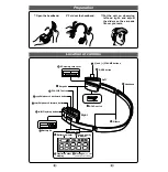
Perform repair work in the working condition having proper grounding for preventing static electricity.
1.1.1 Work table grounding
Put a conductive material (sheet) or steel sheet on the area where the optical pickup is placed and ground the sheet.
1.1.2 Human body grounding
Use an anti-static wrist strap to discharge the static electricity from your body.
1.1.3 Handling of optical pickup
1) The optical pickup for spare parts is supplied with its laser diode shorted to ensure quality during transportation.
After the parts replacement, return to normal by proper procedures. (refer to the pages related)
2) Do not use a tester or etc. for checking the laser diode since the laser diode may be damaged easily by the voltage
of the tester inside battery.
Wrist strap
(Anti-static bracelet)
Iron plate or some metals
to conduct electricity
1.2
Handling of Traverse Unit (laser pickup)
1.2.1
Do not apply a strong shock to the traverse unit (laser pickup) since it is made of precise structure.
1.2.2
To prevent the breakdown of the laser diode, install the flexible cable after removing the short pin for preventing a
electrical charge. When removing or connecting the short pin, finish the job in as short time as possible.
Also, cut out the short land of the flexible cable using nippers and etc. after replacing the optical pickup. Refer to
TRAVERSE UNIT DISASSEMBLY” in this manual for the handling of the traverse unit.
1.2.3
Be careful not to apply excessive stress to the flexible board (FPC Board) since it may cause cutting.
1.2.4
Do not turn the variable resistor of the laser power since it is not adjustable.
Summary of Contents for DVM-4800
Page 3: ...3 DVM 4800 ...
Page 20: ...20 DVM 4800 6 ABBREVIATIONS MOVING PICTURE EXPERTS GROUP ...
Page 21: ...21 DVM 4800 ...
Page 45: ...8 7 6 5 4 3 2 1 A B C D E DVM 4800 45 10 WIRING DIAGRAM ...
Page 57: ...57 4 3 2 1 A B C D E DVM 4800 SCHEMATIC DIAGRAMS 11 15 TERMINAL ...
Page 83: ...8 7 6 5 4 3 2 1 A B C D E DVM 4800 63 FOIL SIDE ...


