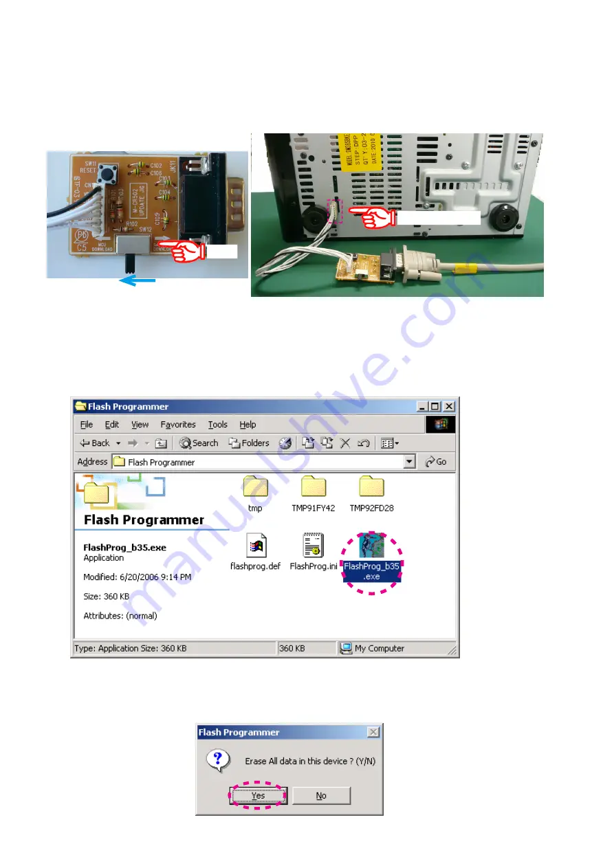
(14) Disconnect the mains cord from the unit.
(15) Connect the RS-232C on the DATA UPDATE KIT and the Serial Port of windows PC with RS-232C cable.
Set the slide switch (SW12) to "MCU DOWNLOAD".
(16) Connect the connective wire (1 pin is lower in a picture) to the bottom chassis of the unit from DATA UPDATE KIT.
Caution
: A connector pin has the connection direction.
Refer to the photograph.
(17) Connect the mains cord into the unit.
(18) Press the ON/STANDBY button to turn on the unit.
(19) Double click FlashProg_b35.exe, and launch the Flash Programmer again.
(20) The Flash Programmer communicates automatically.
When communication succeeds between a unit and a program, a dialog box saying "Erase All data in this device?
(Y/N)" appears.
Click Yes.
1 pin : BLACK wire
SW12
32
Summary of Contents for D-M38S
Page 36: ... 3 Save the FlashProg ini 36 ...
Page 52: ...WIRING DIAGRAM 52 ...
Page 66: ...66 TMP92FD28FG Block Diagram ...
Page 69: ...69 TMPM330FYFG for E3 E2 JP model T5CN5 for EK model MCU IC11 ...
Page 81: ...81 AK4385 INPUT IC15 AK4385 Pin Discriptions AK4385 Block Diagram ...
Page 82: ...82 2 IC s 16ST103GINK MAIN FL81 PIN CONNECTION GRID ASSIGNMENT 1 43 Upper Lower ...
Page 83: ...83 ANODE CONNECTION ...
Page 84: ...84 ...


