background image

11

ENGLISH

Basic version

Advanced version

Information

Simple version

Play back disc

1

2

4

5

3

5

Remote control operation 

buttons

Move the cursor 
(Up/Down/Left/Right)

Confirm the setting

Return to previous menu

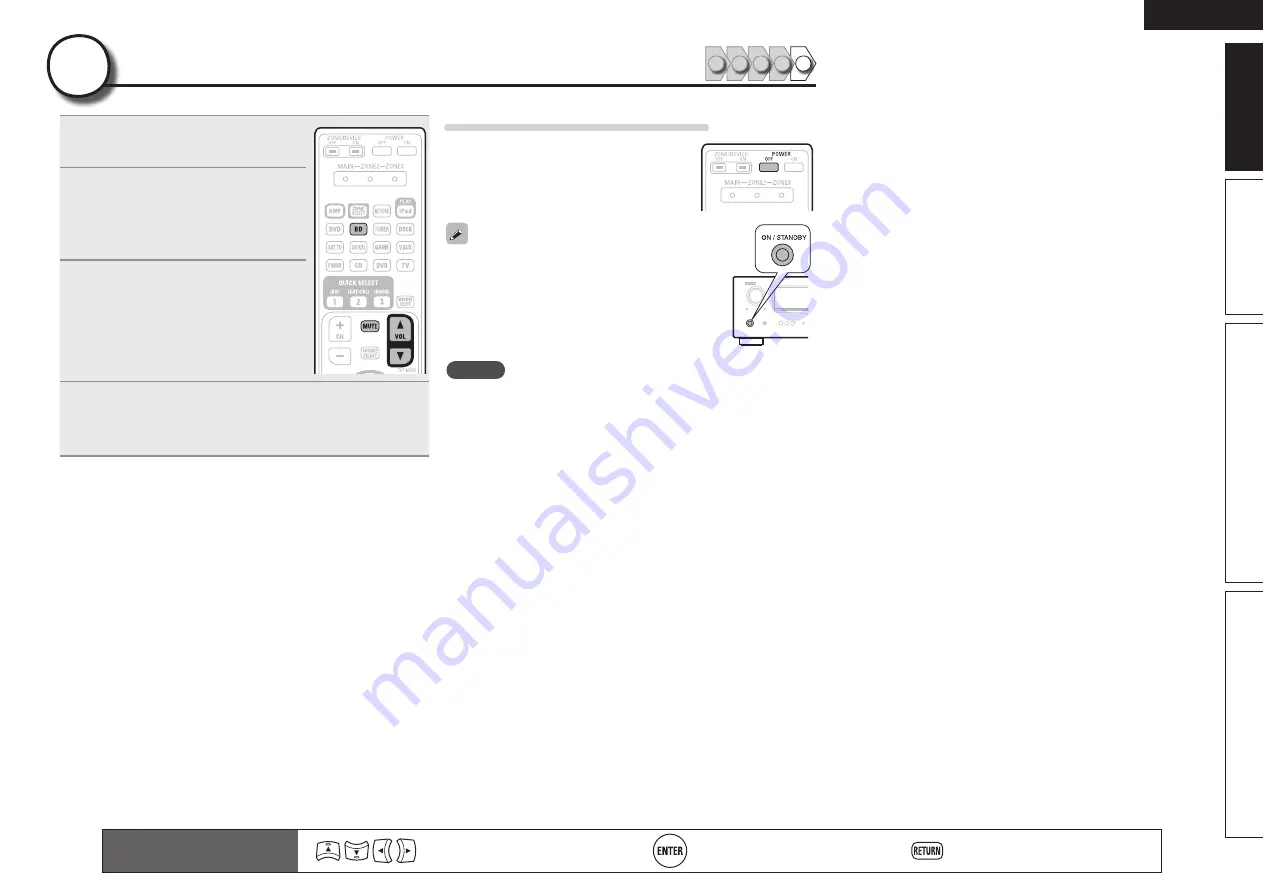
1

Press 

BD

 to switch an input source 

for a player used for playback.

2

Play the component connected to 

this unit.

Make  the  necessary  settings  on  the 
player  (language  setting,  subtitles 
setting, etc.) beforehand.

3

Adjust the sound volume. 

VOL 

d

 ··········································· Volume up

VOL 

f

 ······································ Volume down

MUTE

 ·················································· Muting

4

Set the listening mode.

Set  the  listening  mode  according  to  the  playback  contents 
(cinema, music, etc.) or according to your liking (

v

page 29 

“Selecting a listening mode (Surround mode)”).

When power is switched to standby

Press 

POWER OFF

.

G

Power indicator status in standby mode

H

• Normal standby : Off
• When “HDMI Control” is set to “ON” : Red

You  can  also  switch  the  power  to  standby  by 
pressing 

ON/STANDBY 

on the main unit.

NOTE

During power standby, a minimal amount of power is consumed. To 
totally  cut  off  the  power,  remove  the  power  cord  from  the  power 
outlet.

Summary of Contents for AVR-2311

Page 1: ...v 3 Basic version Version basique Versión básica v 12 Advanced version Version avancée Versión avanzada v 32 Information Part names and functions vpage 72 v 71 Informations Nomenclature et fonctions vpage 72 Información Nombres y funciones de las piezas vpágina 72 v Book 1 English Français Español Book 2 Deutsch Italiano Nederlands Svenska ...

Page 2: ...o de la alimentación eléctrica desconecte el enchufe del enchufe de la pared El enchufe de la alimentación eléctrica se utiliza para interrumpir por completo el suministro de alimentación eléctrica a la unidad y debe de encontrarse en un lugar al que el usuario tenga fácil acceso WAARSCHUWING Om de voeding van dit product volledig te onderbreken moet de stekker uit het stopcontact worden getrokken...

Page 3: ... dalla polvere Scollegate il cavo di alimentazione quando prevedete di non utilizzare l unità per un lungo periodo di tempo Non coprite i fori di ventilazione Non inserite corpi estranei all interno dell unità Assicuratevi che l unità non entri in contatto con insetticidi benzolo o solventi Non smontate né modificate l unità in alcun modo Le aperture di ventilazione non devono essere ostruite copr...

Page 4: ...twortung daß dieses Produkt auf das sich diese Erklärung bezieht den folgenden Standards entspricht EN60065 EN55013 EN55020 EN61000 3 2 und EN61000 3 3 Following the provisions of low voltage directive 2006 95 EC and EMC directive 2004 108 EC the EC regulation 1275 2008 and its frame work directive 2009 125 EC for energy related products ErP DECLARATION DE CONFORMITE Nous déclarons sous notre seul...

Page 5: ...vice to the USB Port 18 Connecting a CD player 19 Connecting an antenna 19 Connecting a external power amplifier 20 Connecting an external control device 20 Playback Basic operation 21 Important information 21 Playing a Blu ray Disc player DVD player 22 Playing a CD player 22 Playing an iPod 22 Tuning in radio stations 25 Playing a USB memory device 28 Selecting a listening mode Surround mode 29 S...

Page 6: ...is unit also supports the ARC Audio Return Channel function which reproduces TV sound with this unit via an HDMI cable used for connecting the unit and a TVz z z The TV should support the ARC function 6 HDMI inputs and 1 output The unit is equipped with 6 HDMI input connectors for connecting devices with HDMI connectors such as a Blu ray Disc player game machine HD video camera etc High definition...

Page 7: ...page 33 n n Before connecting the unit turn off the power to all devices n n For operation of the connected devices refer to the user manuals for each device Play back disc vpage 11 Enjoy Blu ray Disc and DVD in surround sound 5 Set up speakers vpage 6 Use the setup microphone DM A409 included with the product for automatic setup 4 Turn on power vpage 6 3 Connect vpage 4 Connect 7 1 channel speake...

Page 8: ...rovides the speaker installation procedure for the 7 1 channel playback using surround back speakers as an example The default setting is 7 1 channel You can also perform 5 1 channel playback To perform 5 1 channel playback connect5 1 channel speakers only Use the Audyssey Auto Setup function of this unit to automatically detect the number of connected speakers and perform optimal settings for the...

Page 9: ... outlet AC 230 V 50 Hz Power cord supplied HDMI cable sold separately HDMI cable sold separately Blu ray Disc player TV NOTE Do not plug in the power cord until all connections have been completed Do not bundle power cords together with connection cables Doing so can result in humming or noise Connect The Simple version section provides the speaker installation connection and setup methods for the...

Page 10: ...as measurements may be affected by these sounds Cell phones should be placed away from all audio electronics during the measurement process as Radio Frequency Interference RFI may cause measurement disruptions even if the cell phone is not in use Do not unplug the setup microphone from the main unit until Audyssey Auto Setup is completed Do not stand between the speakers and setup microphone or al...

Page 11: ...nel system with surround back speakers For the installing connecting and setup methods of speakers other than the 7 1 channel system with surround back speakers see page 33 Set up speakers Audyssey Auto Setup 3 Set up the remote control unit n n Set up the zone mode Press ZONE SELECT to switch the zone mode to MAIN The MAIN indicator lights Press ZONE SELECT n n Set up the operation mode Press AMP...

Page 12: ...step 9 measuring positions 3 to 6 When measurement of position 6 is completed a Measurements finished message is displayed 3 6 STEP3 Measurement Measurements finished Proceed to Step 4 Analyze AUTO SETUP AUDYSSEY AUTO SETUP MultEQ ENTER Enter RETURN Cancel Retry Next Calculation Set up speakers Audyssey Auto Setup STEP 1 Preparation 4 Connect the setup microphone to the SETUP MIC jack of this unit...

Page 13: ...ce Check Ch Level Check Crossover Check Next Store AUTO SETUP AUDYSSEY AUTO SETUP MultEQ ENTER Enter RETURN Cancel Subwoofers may measure a greater reported distance than the actual distance due to added electrical delay common in subwoofers If you want to check another item press RETURN 13Use ui to select Next 1 Store and then press ENTER STEP 6 Store 14Select Store and then press ENTER Save the ...

Page 14: ...er connections Examples Error details Measures Caution No microphone or Speaker Retry Check cause of problem AUTO SETUP AUDYSSEY AUTO SETUP MultEQ RETURN Cancel The connected setup microphone is broken or a device other than the supplied setup microphone is connected Not all speakers could be detected The front L speaker was not properly detected Connect the included setup microphone to the SETUP ...

Page 15: ... 3 Adjust the sound volume VOL d Volume up VOL f Volume down MUTE Muting 4 Set the listening mode Set the listening mode according to the playback contents cinema music etc or according to your liking vpage 29 Selecting a listening mode Surround mode When power is switched to standby Press POWER OFF GPower indicator status in standby modeH Normal standby Off When HDMI Control is set to ON Red You ...

Page 16: ...15 Blu ray Disc player vpage 14 vpage 22 DVD player vpage 14 16 vpage 22 Set top box Satellite tuner or cable TV vpage 14 16 Digital video recorder vpage 14 17 Game console vpage 14 Digital camcorder vpage 14 17 Control dock for iPod vpage 18 vpage 22 Audio Playback Connection iPod vpage 18 vpage 24 USB memory device vpage 18 vpage 28 Radio vpage 19 vpage 25 CD player vpage 19 vpage 22 For speaker...

Page 17: ...signals cannot be converted into analog signals When a non standard video signal from a game machine or some other source is input the video conversion function might not operate Component video input signals cannot be converted into Video format A menu is output via the HDMI connector or component video connector Examples of on screen display Menu screen Status display screen When the input sourc...

Page 18: ...nnection both this unit and TV or the player need to support the copyright protection system known as HDCP High bandwidth Digital Content Protection System HDCP is copyright protection technology comprised of data encryption and authentication of the connected AV device This unit supports HDCP If a device that does not support HDCP is connected video and audio are not output correctly Read the own...

Page 19: ...on the combination of devices the video signals may not be output n n Settings related to HDMI connections Set as necessary For details see the respective reference pages Input Assign vpage 49 Set this to change the HDMI input connector to which the input source is assigned HDMI Setup vpage 61 Make settings for HDMI video audio output RGB Range Auto Lip Sync HDMI Audio Out HDMI Control Standby Sou...

Page 20: ...onnector to which the input source is assigned Input Assign vpage 49 in Set as Necessary Connecting a set top box Satellite tuner cable TV You can watch satellite or cable TV Select the connector to use and connect the device For instructions on HDMI connections see Connecting an HDMI compatible device vpage 14 Cables used for connections Video cable sold separately Video cable Yellow Component vi...

Page 21: ...Necessary NOTE To record video signals through this unit use the same type of video cable for connection between this unit and the player as used for connection between this unit and the recorder Connecting a digital camcorder You can enjoy video and audio from a digital comcorder You can enjoy games by connecting a game machine via the V AUX input connector In this case select the input source to...

Page 22: ...SB memory device to the USB Port You can enjoy music stored on an iPod or USB memory device Cables used for connections To connect an iPod to this unit use the USB cable supplied with the iPod USB memory device iPod or When you want to playback a video file stored on an iPod use a DENON control dock for iPod ASD 1R ASD 11R ASD 3N ASD 3W ASD 51N and ASD 51W sold separately vpage 18 Connecting a con...

Page 23: ...tion 75 Ω Coaxial cable Ground AM outdoor antenna AM loop antenna supplied Black White FM indoor antenna supplied n n AM loop antenna assembly 1 Put the stand section through the bottom of the loop antenna from the rear and bend it forward Stand Square hole Projecting part Loop antenna 2 Insert the projecting part into the square hole in the stand n n Using the AM loop antenna Suspending on a wall...

Page 24: ...tions for linked operation via the TRIGGER OUT jack Trigger Out vpage 65 in Set as Necessary NOTE If the permissible trigger input level for the connected device is larger than 12V 150mA or has shorted the TRIGGER OUT jack cannot be used In this case turn off the power to the unit and disconnect it Connecting a external power amplifier You can use this unit as a pre amp by connecting a commerciall...

Page 25: ...cted input source is highlighted q w e q Input Source The name of the highlighted input source is displayed w Recently used sources The recently used input sources up to five are displayed e Icons for the input sources in the different categories are displayed w Use uio p to select the input source then press ENTER The input source is set and the source selection menu is turned off When using with...

Page 26: ...ting a control dock for iPod w Set the iPod in the DENON control dock for iPod 2 Press POWER ON to turn on power to the unit 3 Press DOCK to switch the input source to DOCK If Browse mode is selected in step 4 the following screen is displayed on a TV screen depending on the connected control dock for iPod When using an ASD 1R When using an ASD 11R iPod Music Video Track Select Track Select Track ...

Page 27: ...Pod equipped with a slide show or video function 1 Press and hold SEARCH to set the Remote mode Remote iPod or Dock Remote is displayed on the display of this unit 2 Watching the iPod s screen use ui to select Photos or Videos Depending on the iPod model it may be necessary to operate the iPod unit directly 3 Press ENTER until the image you want to view is displayed TV Out at the iPod s Slide show...

Page 28: ...Use ui to select the item then press ENTER or p to select the file to be played 6 Press ENTER p or 1 Playback starts You can specify the duration of the on screen display to be displayed default 30 sec at menu iPod vpage 65 Press uio p to return to the original screen To play back compressed audio with extended bass or treble reproduction we recommend playback in RESTORER mode vpage 57 The default...

Page 29: ... automatically at Auto Preset vpage48 If AutoPreset isperformedafterperforming Manual Preset the Manual Preset settings will be overwritten 1 Tune in the broadcast station you want to preset 2 Press MEMORY 3 Press SHIFT to select the block A to G in which to preset the channel 1 to 8 per block then press CH CH or 1 8 to select the preset number 4 Press MEMORY again to complete the setting To prese...

Page 30: ...S is displayed PTY Program Type PTY identifies the type of RDS program The program types and their displays are as follows NEWS News WEATHER Weather AFFAIRS Current Affairs FINANCE Finance INFO Information CHILDREN Children s program SPORT Sports EDUCATE Education SOCIAL Social Affairs DRAMA Drama RELIGION Religion CULTURE Culture PHONE IN Phone In SCIENCE Science TRAVEL Travel VARIED Varied LEISU...

Page 31: ... Name Jamp to album Program Category RDS PTY TP RT RDS Station Program Category Traffic Information Radio Text ON SEARCH Mode A5 FM 90 10MHz Tuning CH 3 Press CH or CH TP search begins automatically If no TP station is found with the above operation all the reception bands are searched The station name is displayed on the display after searching stops If no other TP station is found when all the f...

Page 32: ...default 30 sec at menu USB vpage 65 Press uio p to return to the original screen To play back compressed audio with extended bass or treble reproduction we recommend playback in RESTORER mode vpage 57 The default setting is Mode 3 If the USB memory device is divided into multiple partitions only the top partition can be selected This unit is compatible with MP3 files conforming to MPEG 1 Audio Lay...

Page 33: ...al input The surround signal recorded in source is played as surround playback The sound is played according to the settings of the speaker size in Speaker Config vpage 58 Surround back channel or front height channel signals that are not recorded in source can be created 2 channel Multi channel Surround DENON original surround playback vpage 31 The surround effects suitable for the source type or...

Page 34: ...BY DIGITAL Plus EX DOLBY D EX DOLBY DIGITAL Plus PLgx CINEMA DOLBY D PL x C DOLBY DIGITAL Plus PLgx MUSIC DOLBY D PL x M DOLBY DIGITAL Plus PLgz HEIGHT DOLBY D PL z DOLBY TrueHD DOLBY TrueHD DOLBY TrueHD DOLBY TrueHD EX DOLBY HD EX DOLBY TrueHD PLgx CINEMA DOLBY HD PL x C DOLBY TrueHD PLgx MUSIC DOLBY HD PL x M DOLBY TrueHD PLgz HEIGHT DOLBY HD PL z DTS 5 1ch DTS ES Discrete 6 1 DTS ES Matrix 6 1 ...

Page 35: ...his is the mode for playing in stereo The tone can be adjusted Sound is output from the front left and right speakers and subwoofer If multichannel signals are input they are mixed down to 2 channel audio and are played 1 Playing the source vpage 22 28 2 Press D ST to select STEREO Stereo playback begins Direct playback Sound recorded in source is played as is Surround back signals or front height...

Page 36: ...ck speakers vpage 33 F Playback Advanced operation vpage 39 F Playback in ZONE2 Separate room vpage 42 F How to make detailed settings vpage 44 F Operating the connected devices by remote control unit vpage 67 Advanced version Here we explain functions and operations that let you make better use of this unit ...

Page 37: ...ont height speaker Point slightly downwards At least 1 m Surround back speaker Point slightly downwards Front speaker z z Recommended for Dolby Pro Logic gz NOTE It is not possible to use the surround back speakers and front height speakers simultaneously When 7 1ch Front height speaker installed FL FR FHR FHL C SL SR SW z1 z2 z3 Listening position z1 22 30 z2 22 45 z3 90 110 When 6 1ch Surround b...

Page 38: ...7 to Front Height FL FR FHR FHL C SW SL SR 6 1 channel Surround back speaker connection If using only one surround back speaker with a 6 1 channel connection connect to the L side of the SURR BACK AMP ASSIGN terminal For speaker settings in this case see When 6 1ch Surround back speaker installed vpage 33 For 6 1 channel Surround back speaker playback set Amp Assign in Set up speakers vpage 37 to ...

Page 39: ...annel playback is available Front speakers can be used separately depending on the speaker s specifications or playback source such as front speakers A for multichannel playback and front speakers B for 2 channel playback vpage 60 Front Speaker Setup For speaker impedance and speaker cable connections see page 4 5 1 channel connection For 5 1 channel playback set Amp Assign in Set up speakers vpag...

Page 40: ... bi amp connection is to connect separate amplifiers to the tweeter terminals and woofer terminals of speakers compatible with the bi amp function This prevents the back electromotive force returned force without output of the woofer sent to the tweeter which affects the sound quality of the tweeter and you can enjoy playback with higher quality sound In this case set Amp Assign of Set up speakers...

Page 41: ...rminals This section provides the setup methods of speaker systems other than the 7 1 channel system with surround back speakers For the setup methods of the 7 1 channel system with surround back speakers see Set up speakers Audyssey Auto Setup vpage 6 of Simple version First install and connect the speakers to this unit Before Auto Setup measurement the settings shown below can be made Changing t...

Page 42: ...for no surround back speakers to be used In this case go to step 9 Surround Back can be set when Amp Assign is set to Normal 7 GWhen Front is selected in step 6H Press o p to select a front speaker A Select this to use front speaker A B Select this to use front speaker B A B Select this to use front speakers A and B simultaneously Set up speakers 8 GWhen Subwoofer is selected in step 6H Use o p to...

Page 43: ... each device for details beforehand When PowerOffControl onthemenuissetto OFF vpage61 this unit is not set to standby even if the connected device is in the standby mode When connection changes are implemented such as adding connections to HDMI devices linked operations may be initialized In this case you will need to reconfigure the settings When HDMI Control is set to ON it is not possible to as...

Page 44: ...L Surround R S Back L S Back R Fader 0 0dB 0 0dB 0 0dB 0 0dB 0 0dB 0 0dB 0 0dB 0 0dB CHANNEL LEVEL Select Front Rear 4 Use ui to select the speaker The speaker that can be set switches each time one of the buttons is pressed 5 Use o p to adjust the volume In the case of a subwoofer pressing o when it is at 12 dB will change the setting to OFF When a headphone jack is inserted the headphone channel...

Page 45: ...io video recording connectors DVR outputs you can record the audio or video from a different program source while listening to the currently played track 1 Press ZONE2 REC SELECT ZONE2 Source is shown on the display 2 Turn SOURCE SELECT until RECOUT Source is displayed The indicator illuminates ZONE2 Source ZONE2 TUNER ZONE2 USB iPod RECOUT USB iPod RECOUT DOCK RECOUT Source 3 Turn SOURCE SELECT t...

Page 46: ... audio signals connected to this unit s ZONE2 output terminals ZONE2 OUT are output to the ZONE2 s amplifier and played with that amplifier Connection ZONE2 R L R L AUX IN This unit MAIN ZONE ZONE2 We recommend using high quality pin plug cables for audio connections in order to prevent noise Also be sure to read the operating instructions of the connected devices NOTE It is not possible to play t...

Page 47: ...NE2 turns off Power in ZONE2 can be turned on or off by pressing ZONE2 ON OFF on the main unit 4 Press the input source select button The audio signal of the selected source is output to ZONE2 Turn SOURCE SELECT after pressing ZONE2 REC SELECT on the main unit to select an input source When power for both MAIN ZONE and ZONE2 is set to ON power of the MAIN ZONE only can be turned off Select MAIN in...

Page 48: ...ey Auto Setup procedure has been performed 10 4 Manual Setup Make detailed speaker settings Speaker Setup HDMI Setup Audio Setup ZONE2 Setup Option Setup MANUAL SETUP Speaker Setup Sets the speaker size and distance the channel level etc 58 HDMI Setup Makes settings for HDMI video audio output 61 Audio Setup Makes settings for audio playback 61 ZONE2 Setup Makes settings for audio playback in a ZO...

Page 49: ...R Enter Select RETURN Cancel Default HDMI1 HDMI2 None HDMI3 HDMI4 HDMI5 HDMI6 HDMI None Coax1 Opt1 Coax2 Opt2 None None DIGITAL None 1 RCA None 2 RCA None None None COMP INPUT SETUP INPUT ASSIGN e Press ENTER q Input Assign BD HDMI1 e Input Assign BD HDMI1 Press ENTER q Use uio p to move to the item you want to set w Press ENTER to set to the mode in which the setting can be made e 0 1 is displaye...

Page 50: ... x y z 9 J K L j k l 5 0 Space z The input character type can be switched by pressing SHIFT while the display name is being changed For entering the characters assigned to one number button continuously press p to move the cursor to the right after entering a character then enter the next character For entering characters assigned to separate buttons press the number button continuously The cursor...

Page 51: ...put are as shown below GUpper case characters Numbers SymbolsH ABCDEFGHIJKLMNOPQRSTUVWXYZ 0123456789 z GLower case characters Numbers SymbolsH abcdefghijklmnopqrstuvwxyz 0123456789 _ The input character type can be switched by pressing SHIFT while the display name is being changed 5 Repeat steps 3 and 4 to change the name 6 Use uio p to select then press ENTER Remote control operation buttons Move...

Page 52: ...tomatically detect input signal and playback RETURN Return Repeat Shuffle All OFF INPUT SETUP PLAYBACK MODE Repeat all songs RETURN Return Auto Preset vpage 48 Input Assign vpage 49 Rename vpage 51 Video vpage 50 Source Level vpage 52 Input Mode vpage 51 Playback Mode vpage 52 Preset Skip vpage 48 Preset Name vpage 49 Remote control operation buttons Move the cursor Up Down Left Right Confirm the ...

Page 53: ...o the input sources BD DVD TV SAT CBL DVR GAME V AUX DOCK HDMI 1 HDMI 2 HDMI 3 HDMI 4 HDMI 5 HDMI 6 None Do not assign an HDMI input connector to the selected input source At time of purchase the settings of the different input sources are as shown below Input source BD DVD TV SAT CBL DVR GAME V AUX DOCK Default setting HDMI 1 HDMI 2 None HDMI 3 HDMI 4 HDMI 5 HDMI 6 None An input source to which a...

Page 54: ...Setting items Setting details Video Mode Make settings for video processing BD z DVD TV z SAT CBL DVR GAME z V AUX DOCK Auto Process video automatically based on the HDMI content information Movie Process video automatically regardless of contents Game Process video automatically based on game contents If Video Mode is set to Auto the mode is switched according to the input contents If a source is...

Page 55: ...t when i p Scaler is set to anything other than OFF z z BD TV or GAME can be set when HDMI vpage 49 or Component vpage 50 has been assigned Input Mode Default settings are underlined The input modes available for selection may vary depending on the input source Setting items Setting details Input Mode Set the audio input modes for the different input sources Auto Automatically detect input signal ...

Page 56: ... iPod ASD 3N ASD 3W ASD 51N or ASD 51W is connected ON Shuffle playback mode is enabled OFF Shuffle playback mode is canceled n n For USB memory device playback ON Shuffle playback mode is enabled OFF Shuffle playback mode is canceled Remote control operation buttons Move the cursor Up Down Left Right Confirm the setting Return to previous menu Audio Video Adjust The sound being played in the surr...

Page 57: ... we recommend setting to the values below Dolby Digital sources 0dB DTS movie sources 0dB DTS music sources 10dB C Image Assign center channel signal to front left and right channels for wider sound 0 0 1 0 0 3 Remote control operation buttons Move the cursor Up Down Left Right Confirm the setting Return to previous menu Setting items Setting details Panorama Assign front L R signal also to surrou...

Page 58: ... is output from the front height speaker OFF Audio is not output from the front height speaker NOTE F Height is displayed for the following settings When Amp Assign vpage 58 is set to Front Height When the Speaker Config F Height setting vpage 59 is set to other than None F Height cannot be set if the HD Audio source being played includes a front height channel In this case the Front height channe...

Page 59: ...ressing MULTEQ makes this setting NOTE MultEQ and Manual cannot be selected when EQ Customize is set to Not Used vpage 62 When using headphones MultEQ is automatically set to OFF Setting items Setting details Dynamic EQ Solve the problem of deteriorating sound quality as volume is decreased by taking into account human perception and room acoustics Works with MultEQ ON Use Dynamic EQ OFF Do not us...

Page 60: ...namic Volume OFF Dynamic EQ OFF Dynamic Volume OFF Dynamic EQ ON Dynamic Volume Day GOperations with the main unitH Press DYNAMIC VOLUME Each time DYNAMIC VOLUME is pressed the setting is changed as shown below Dynamic Volume Midnight Dynamic Volume Evening Dynamic Volume OFF Dynamic Volume Day n n Manual EQ Default settings are underlined Use the graphic equalizer to adjust the tone of each speak...

Page 61: ...splayed Pressing RESTORER on the remote control unit or the main unit makes this setting OFF Mode 1 RESTORER 64 Mode 2 RESTORER 96 Mode 3 RESTORER HQ n n Audio Delay Default settings are underlined While viewing video manually adjust the time to delay audio output Setting details 0ms 200ms This item can be set within the range of 0 to 100 ms when Auto Lip Sync is set to ON and when a TV compatible...

Page 62: ... Dynamic EQ and Dynamic Volume vpage 55 56 Manual Setup can be used without changing the settings Please set if necessary Setting items Setting details Amp Assign Set the speakers connected to this unit Normal Set when using 7 1 channel Front Center Surround Surround Back Subwoofer speakers ZONE2 Set for connecting the speakers for ZONE2 to the SURR BACK AMP ASSIGN terminals Front Height Set for c...

Page 63: ... 0 m 10 0 ft Set the difference in the distance between the speakers to less than 6 0 m 20 ft NOTE Speakers set to None in Speaker Config vpage 58 are not displayed Remote control operation buttons Move the cursor Up Down Left Right Confirm the setting Return to previous menu Setting items Setting details Speaker Config Continued Surround Set the presence and size of the surround speakers Large Us...

Page 64: ...capability of the speaker being used Crossover Set the crossover frequency 40Hz 60Hz 80Hz 90Hz 100Hz 110Hz 120Hz 150Hz 200Hz 250Hz Advanced Specify crossover frequency for each speaker Front Center Surround S Back F Height Select the speaker 40Hz 60Hz 80Hz 90Hz 100Hz 110Hz 120Hz 150Hz 200Hz 250Hz Set the crossover frequency Crossover Frequency can be set when the Bass Setting SW Mode vpage 59 sett...

Page 65: ...to put into standby when the power is on Last This item is set at the last used input source HDMI 1 HDMI 2 HDMI 3 HDMI 4 HDMI 5 HDMI 6 Put the respective input source into standby Standby Source can be set when HDMI Control is set to ON Setting items Setting details Power Off Control Links the power standby of this unit to external equipment All If power to a connected TV is turned off independent...

Page 66: ...z 150Hz 200Hz 250Hz This setting can be set made 2ch Direct Stereo Subwoofer is set to Yes If the 2ch Direct Stereo Front setting is Large and the SW Mode setting is LFE Full Band is displayed and the setting cannot be made Dist FL Dist FR Select the speaker 0 00m 18 00m 3 60m 0 0ft 60 0ft 12 0ft Set the distance to the speaker Set so that the difference between the front left speaker and front ri...

Page 67: ...Adjust high frequency range treble 10dB 10dB 0dB HPF Make settings for cutting the low range to reduce distortion in the bass ON The low range is attenuated OFF The low range is not attenuated Level Lch Adjust the left channel output level 12dB 12dB 0dB The Level Lch can be set when Channel vpage 63 is set to Stereo Level Rch Adjust the right channel output level 12dB 12dB 0dB The Level Rch can be...

Page 68: ...I Make the settings related to displays on the TV screen Screensaver Make screensaver settings ON The screen saver is activated during menu display iPod USB iPod or TUNER screen display if no operation is performed for an approximately 3 minute continuous period When you press uio p the screensaver is cancelled and the screen before that screen saver started is displayed OFF Screensaver is not act...

Page 69: ...t to ON n n When setting for input source Activate trigger out when the input source set to ON is selected Active for the zone set to ON with When Setting for Zone n n When setting for surround mode Activate trigger out when the surround mode set to ON is selected Active when the MAIN ZONE set to ON with When Setting for Zone is selected and when the input source set to ON with When Setting for In...

Page 70: ...gnals DISCRETE with DTS ES Discrete signals Dialogue normalization function This function is automatically activated when playing Dolby Digital sources It automatically corrects the standard signal level for individual program sources The correction value can be checked using the STATUS The figure is the corrected value This cannot be changed HDMI Information Show information about HDMI input outp...

Page 71: ...Pod DOCK Control dock for iPod USB iPod iPod or USB memory device connected to the USB port TUNER Radio of this unit z z If a preset code is registered for this button the remote control unit of this unit can control another devices NOTE If the mode of the remote control unit is set to other than amp operation mode press AMP to switch the remote control unit to the amp operation mode to perform th...

Page 72: ...name Trigger Out Remote ID Setup MANUAL SETUP OPTION SETUP Search preset codes to register in the RC 5 Pressing ui select the category of device for preset registration Then press ENTER or p Blu ray CD CD Recorder CABLE CABLE PVR DVD DVD Recorder HD DVD IPTV STB PVR D I J L M O P S V Y MANUAL SETUP OPTION SETUP REMOTE PRESET CODES Select the device category 6 Pressing ui select the first character...

Page 73: ...ICK2 NG QUICK3 Return When the code is registered The zone mode indicator flashes twice When the code is not registered correctly The mode indicator slowly flashes once Perform from step 9 again When an input number is not correct Press POWER ON once then perform the operations from step 9 again 12Operate the device being used to check the operation If the device is operating press QUICK SELECT 1 ...

Page 74: ... power on standby Default SONY TV INPUT Switch TV input Default SONY z zThis may power some devices on standby n n Set top box for satellite SAT cable CBL IP TV operation Operation buttons Function ZONE DEVICE ON Power onz ZONE DEVICE OFF Power standbyz CH Switch channels up down MENU Menu uio p Cursor operation ENTER Enter SETUP Guide RETURN Return 6 7 Manual search fast reverse fast forward 1 Pl...

Page 75: ...s 1 When only using MAIN ZONE 2 When using MAIN ZONE ZONE2 3 When using MAIN ZONE ZONE2 ZONE3 Default Resetting the remote control unit Settings for the remote control unit are returned to the default setting 1 Press and hold POWER ON and ZONE DEVICE ON for at least 3 seconds The zone mode indicator flashes twice 2 Press 9 8 and 1 in that order MAIN indicator flashes four times All the settings ar...

Page 76: ...l signals are input When playing HD Audio sources the indicator lights when a signal from an extension channel a channel other than the front center surround surround back or LFE channel is input If there are two or more extension channels the and indicators light eInformation display The input source name surround mode setting values and other information are displayed here rOutput signal channel...

Page 77: ...rs 15 18 Q3TRIGGER OUT jack 20 NOTE Do not touch the inner pins of the connectors on the rear panel Electrostatic discharge may cause permanent damage to the unit Q6Tuner reception mode indicators These light according to the reception conditions when the input source is set to TUNER STEREO In the FM mode this light when receiving analog stereo broadcasts TUNED Lights when the broadcast is properl...

Page 78: ...tereo button D ST DSP simulation button SIMULATION Q4SHIFT button 25 46 Q5TV operation buttons TV POWER INPUT 70 Q6Remote control signal transmitter 75 Q7Power buttons POWER ON OFF 6 11 Q8Master volume control buttons VOL 21 Q9Channel level button CH LEVEL 40 W0RETURN button 47 W1ENTER button 45 47 W2RESTORER button 57 W3Pure direct button PURE 31 W4Number buttons 25 69 70 W5Character buttons 46 W...

Page 79: ...es not operate even when the remote control unit is operated close to the unit The supplied batteries are only for verifying operation When inserting the batteries be sure to do so in the proper direction following the q and w marks in the battery compartment To prevent damage or leakage of battery fluid Do not use a new battery together with an old one Do not use two different types of batteries ...

Page 80: ... MultEQ is a registered trademark of Audyssey Laboratories Audyssey Dynamic EQ is a registered trademark of Audyssey Laboratories Audyssey Dynamic Volume is a trademark of Audyssey Laboratories Made for iPod and Made for iPhone mean that an electronic accessory has been designed to connect specifically to iPod or iPhone respectively and has been certified by the developer to meet Apple performance...

Page 81: ... S D D D Dz2 D Sz8 S S DOLBY DIGITAL Plus S D D D Dz2 D Sz8 S S DOLBY TrueHD S D D D Dz2 D Sz8 S S DTS SURROUND S D D D Dz2 D Sz8 S S DTS 96 24 S D D D Dz2 D Sz8 S S DTS HD S D D D Dz2 D Sz8 S S DTS Express S D D D Dz2 D Sz8 S S MULTI CH STEREO S D D D Dz2 D S S ROCK ARENA S D D D Dz2 D S S S S JAZZ CLUB S D D D Dz2 D S S S S MONO MOVIE S D D D Dz2 D S S S S VIDEO GAME S D D D Dz2 D S S S S MATRIX...

Page 82: ...S HD S S S Sz14 S S S S DTS Express S S S Sz14 S S S S MULTI CH STEREO S S S S S S S ROCK ARENA S S Sz16 S S S S JAZZ CLUB S S S S S S S MONO MOVIE S S S S S S S VIDEO GAME S S S S S S S MATRIX S S S S S S S VIRTUAL S S S S S z3 Only when SW Mode is set to LFE Main vpage 59 sound is output from the subwoofer z12 This item can be selected when a Dolby Digital or DTS or DVD Audio signal is played z1...

Page 83: ...I RES F DTS ES DSCRT6 1 z1z3 F D DTS ES MTRX6 1 z1z3 F D DTS SURROUND S S F DTS 96 24 F DTS HD PLgx CINEMA z2z3 S S S S S S S DTS HD PLgx MUSIC z1z3 S S S S S S S DTS HD PLgz z4 S S S S S S S DTS EXPRESS F DTS HD NEO 6 z1z3 S S S S S S DTS NEO 6 CINEMA S S S DTS NEO 6 MUSIC S S S DOLBY SURROUND DOLBY TrueHD F DOLBY DIGITAL F DOLBY DIGITAL EX z1z3 S S S S DOLBY D HD EX z1z3 S S DOLBY DIGITAL S F F ...

Page 84: ...7 1 z3 F D 7 1 DIRECT DIRECT S S S S S S S S S S S S S S S S S PURE DIRECT PURE DIRECT S S S S S S S S S S S S S S S S S DSP SIMULATION MULTI CH STEREO S S S S S S S S S S S S ROCK ARENA S S S S S S S S S S S S JAZZ CLUB S S S S S S S S S S S S MONO MOVIE S S S S S S S S S S S S VIDEO GAME S S S S S S S S S S S S MATRIX S S S S S S S S S S S S VIRTUAL S S S S S S S S S S S S STEREO STEREO F S F S ...

Page 85: ... A VIDEO Only the menu is displayed A z2 A VIDEO 30 OFF A A S A A A S VIDEO A S VIDEO 31 OFF A A S S A A 32 OFF A S A A A COMPONENT A A COMPONENT z2 A 33 OFF A S A S A VIDEO A VIDEO 34 OFF A S S A A S VIDEO A S VIDEO 35 OFF A S S S A 36 OFF S A A A HDMI A A A z2 A 37 OFF S A A S A VIDEO A VIDEO 38 OFF S A S A A S VIDEO A S VIDEO 39 OFF S A S S A 40 OFF S S A A COMPONENT A A COMPONENT z2 A 41 OFF S...

Page 86: ...Pro Logic gx Dolby Pro Logic gx is a further improved version of the Dolby Pro Logic g matrix decoding technology Audio signals recorded in 2 channels are decoded to achieve a natural sound with up to 7 1 channels There are three modes Music suited for playing music Cinema suited for playing movies and Game which is optimized for playing games Dolby Pro Logic gz Dolby Pro Logic gz introduces a new...

Page 87: ...AC Explanation of terms P Progressive sequential scanning This is a scanning system of video signal that displays 1 frame of video as one image Compared to the interlace system this system provides images with less flickering and bleeding Protection Circuit This is a function to prevent damage to components within the power supply when an abnormality such as an overload excess voltage occurs or te...

Page 88: ...does not operate properly Reset the microprocessor 86 GVideoH Symptom Cause Solution Page No picture appears Check the TV connection Set the TV input correctly 5 6 Troubleshooting GAudioH Symptom Cause Solution Page Audio is not output Check the connections for all devices Check the speaker connections Check whether the audio device power is turned on Adjust the master volume Cancel the mute mode ...

Page 89: ...this unit disconnect the iPod and then reconnect it GUSB memory deviceH Symptom Cause Solution Page When a USB memory device is connected USB is not displayed on the menu The set cannot recognize a USB memory device Check the connection A USB memory device not conforming to mass storage class is connected Connect a USB memory device conforming to mass storage class A USB memory device cannot be co...

Page 90: ...e reset to their default values SURROUND MODE 0 SURROUND MODE 1 ON STANDBY 1 Turn off the power using ON STANDBY 2 Press ON STANDBY while simultaneously pressing SURROUND MODE 0 and SURROUND MODE 1 3 Once the display starts flashing at intervals of about 1 second release the two buttons If in step 3 the display does not flash at intervals of about 1 second start over from step 1 ...

Page 91: ...l audio interface n n Video section Standard video connectors Input output level and impedance 1 Vp p 75 Ω Frequency response 5 Hz 10 MHz 1 3 dB Color component video connector Input output level and impedance Y brightness signal 1 Vp p 75 Ω PB CB signal 0 7 Vp p 75 Ω PR CR signal 0 7 Vp p 75 Ω Frequency response 5 Hz 60 MHz 0 3 dB when Video Convert set to OFF n n Tuner section FM AM Note μV at 7...

Page 92: ...v vNumerics 2 1 channel 35 2ch Direct Stereo 61 3D 14 5 1 channel 33 35 6 1 channel 33 34 7 1 channel 4 33 34 v vA Accessories 1 Adjust CH 56 Adobe RGB color Adobe YCC601 color 82 AFDM 53 AM loop antenna 19 Amp Assign 58 ARC 14 Aspect 51 Audio Adjust 53 Audio cable 5 16 17 19 20 Audio Delay 57 Audio Setup 61 Audio Video Adjust 52 Audyssey Auto Setup 6 37 Audyssey Dynamic EQ 55 82 Audyssey Dynamic ...

Page 93: ... mode 22 24 Remote Preset Codes 65 Rename 51 Repeat 52 Resetting the microprocessor 86 Resolution 51 RESTORER 57 RGB Range 61 Room Size 53 RT 27 v vS Sampling frequency 83 S Back 54 59 Screensaver 64 Selecting the input source 21 Setup Lock 65 Shuffle 52 Sleep timer 40 Source Delete 64 Source Level 52 Speaker Connect 4 34 Install 4 33 Set up 6 37 Speaker cable 5 Speaker Config 58 Speaker impedance...

Page 94: ...D M Holdings Inc Printed in China 5411 10425 205D www denon com ...

Reviews: