background image

ENGLISH

ENGLISH

Troubleshooting

Page

Measures

Cause

Symptom

45

Troubleshooting

If a problem should arise,first check the following.
1. Are the connections correct?
2. Have you operated the receiver according to the operating instructions?
3. Are the speakers, turntable and other components operating property?

If this unit is not operating properly, check the items listed in the table below. Should the problem
persist, there may be a malfunction. Disconnect the power immediately and contact your store of
purchase.

Display not lit and
sound not produced
when POWER switch
set to on.

• Power supply cord not plugged in

securely.

• Check the insertion of the power

supply cord plug.

• Turn the power on with the remote

control unit after turning the
POWER switch on.

15

8

Display lit but sound
not produced.

• Speaker cables not securely

connected.

• Improper setting of the INPUT

SELECTOR knob.

• Volume control set to minimum.
• MUTING is on.
• Digital signals not input. Digital input

selected.

• Connect securely.

• Set to a suitable position.

• Turn volume up to suitable level.
• Switch off MUTING.
• Input digital signals or select input

terminals to which digital signals
are being input.

6

16

16
16
18

Display not lit and
power indicator is
flashing rapidly.

• Speaker terminals are short-

circuited.

• The ventilation holes of the set are

blocked.

• The unit is operating at continuous

high power conditions and/or with
inadequate ventilation.

• Switch power off, connect

speakers properly, then switch
power back on.

• Turn off the set’s power, then

ventilate it well and allow it to cool
down.
Once the set has cooled down,
turn the power back on.

• Turn off the set’s power, then

ventilate it well and allow it to cool
down.
Once the set has cooled down,
turn the power back on.

5, 6

2, 5

2, 5

Sound produced only
from one channel.

• Incomplete connection of speaker

cables.

• Incomplete connection of input/

output cables.

• Connect securely.

• Connect securely.

5, 6

5~7,

11~15

Positions of
instruments reversed
during stereo playback.

• Reverse connections of left and

right speakers or left and right
input/output cables.

• Check left and right connections.

6

Page

Measures

Cause

Symptom

Sound is distorted.

• Stylus pressure too weak.
• Dust or dirt on stylus.

• Apply proper stylus pressure.
• Check stylus.


This unit does not
operate properly when
remote control unit is
used.

• Batteries dead.
• Remote control unit too far from

this unit.

• Obstacle between this unit and

remote control unit.

• Different button is being pressed.

<

and 

>

ends of batteries inserted

in reverse.

• Replace with new batteries.
• Move closer.

• Remove obstacle.

• Press the proper button.
• Insert batteries properly.

3
3

3

3

2

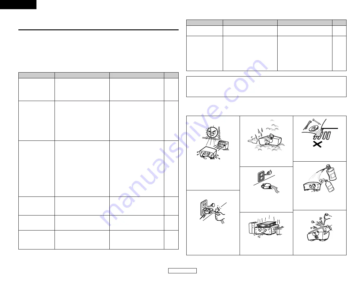
NOTE ON USE

Howling noise
produced when
volume is high.

• Speaker systems too close

together.

• Floor is unstable and vibrates

easily.

• Separate as much as possible.

• Use cushions to absorb speaker

vibrations transmitted by floor.

NOTE:

• For ordinary speaker systems, we recommend setting the crossover frequency to 80 Hz.

When using small speakers, however, setting the crossover frequency to a high frequency
may improve frequency response for frequencies near the crossover frequency.

Avoid high temperatures.
Allow for sufficient heat dispersion
when installed in a rack.

Handle the power cord carefully.
Hold the plug when unplugging the
cord.

Keep the apparatus free from
moisture, water, and dust. 

Unplug the power cord when not
using the apparatus for long
periods of time.

* (For apparatuses with ventilation holes)

Do not obstruct the ventilation holes.

Do not let foreign objects into the
apparatus.

Do not let insecticides, benzene,
and thinner come in contact with
the apparatus.

Never disassemble or modify the
apparatus in any way.

Summary of Contents for AVR-1706

Page 1: ...AV SURROUND RECEIVER AVR 1706 OPERATING INSTRUCTIONS MODE D EMPLOI ...

Page 2: ...abel If you are not sure of the type of power supply to your home consult your product dealer or local power company For products intended to operate from battery power or other sources refer to the operating instructions 12 Grounding or Polarization This product may be equipped with a polarized alternating current line plug a plug having one blade wider than the other This plug will fit into the ...

Page 3: ... Center 12ft Surr L 10ft Surr R 10ft S Back L 10ft S Back R 10ft SW 12ft Digital In Assignment SW Mode Norm Cr Over 80Hz Test Tone TEST TONE Yes Audio Delay COAX1 CD COAX2 AUX OPT1 DVD OPT2 TV Video Input Mode DVD Auto TV Auto VCR Auto A Delay 0ms Auto Surround Mode Auto Surr ON Ext In Subwoofer Level Power Amp Assignment Ext In SW 15dB P Amp S Back page 38 39 page 39 40 page 40 page 41 page 42 pa...

Page 4: ...rround modes Surround modes and their features 25 DSP surround simulation 26 27 Tone control setting Adjusting the sound quality 28 Tone defeat mode 28 Channel Level 28 Listening to the radio Auto preset memory 29 Auto tuning 29 Manual tuning 30 Preset stations 30 Recalling preset stations 30 Advanced Setup Front display 38 System Setup Setting the Speaker Configuration 38 39 Setting the Delay Tim...

Page 5: ... from the tuner or TV away from this unit s power supply cord and input output connection cables Noise or disturbance tends to occur particularly when using indoor antennas or 300 Ω ohm feeder wires We recommend using outdoor antennas and 75 Ω ohm coaxial cables Wall Note Cautions on handling Switching the input source when input terminals are not connected A clicking noise may be produced if the ...

Page 6: ...29 30 o STANDARD NIGHT button 19 24 0 5CH 7CH STEREO button 25 1 DIRECT STEREO button 18 2 V AUX INPUT terminals 12 3 SETUP MIC jack 8 4 SURROUND MODE button 16 5 SURROUND PARAMETER button 19 6 SELECT knob 16 19 28 7 TONE DEFEAT button 28 8 TONE CONTROL button 28 9 MASTER VOLUME control knob 16 0 TUNING up ª down buttons 29 1 STATUS button 17 23 2 DIMMER button 17 3 VIDEO SELECT button 17 4 OUTPUT...

Page 7: ...loudspeakers you are using For optimum performance we recommend using the Auto Setup function If you wish you can set the various settings manually without using Auto Setup page 38 41 Easy setup flow Easy Setup and Operation Placing the speakers Connecting the speakers Connecting a monitor and a DVD player Starting the Auto Setup Playing a DVD with surround sound Auto setup flow 1 Speaker Configur...

Page 8: ...n the protection circuit is activated the speaker output is cut off and the power supply indicator flashes Should this occur please follow these steps be sure to switch off the power of this unit check whether there are any faults with the wiring of the speaker cables or input cables and wait for the unit to cool down if it is very hot Improve the ventilation condition around the unit and switch t...

Page 9: ...B Precautions when connecting speakers If a speaker is placed near a TV or video monitor the colors on the screen may be disturbed by the speaker s magnetism If this should happen move the speaker away to a position where it does not cause this effect NOTE When using only one surround back speaker connect it to the left channel Front speaker systems A Center speaker Surround back speaker systems T...

Page 10: ... 1706 you only need to choose one connection type Component video connection offers the best quality and is required for progressive DVD playback followed by S Video while composite video offers the lowest picture quality of the three connection types For more information about the video up conversion function page 11 To connect the digital audio output from the DVD player you can choose from eith...

Page 11: ...lay time from each speaker corresponding to the listening position e This sets the volume that is output from each speaker Connecting a microphone 1 Connect the microphone for Auto Setup to the SETUP MIC jack on the front panel of the unit 2 Place the microphone forAuto Setup at the actual listening position which will be at the same height as your ears Microphone NOTE A loud test tone is output d...

Page 12: ...equency of your subwoofer speaker can be changed then set the volume to halfway and the crossover filter to maximum or switch off the low pass filter The speaker configuration delay time and channel level measurement values can be checked using the system setup function page 38 41 2 Check the results of the speaker detection Example 7 1 channel systems Speaker 3 4 1 Subwoofer Surround and Surround...

Page 13: ...one channel of the surround speakers was detected Sound was output from the R channel when only one surround back speaker was connected The surround back speaker was detected but the surround speaker was not detected Check that the pertinent speakers are properly connected w The speaker polarity is connected in reverse Check the polarity of the pertinent speakers For some speakers this display may...

Page 14: ...udio signal Video signal White Red Component video terminal H Component video cable Y PB CB PR CR Green Blue Red IN OUT OUT IN IN OUT OUT IN Connecting Other Sources With the AVR 1706 the Video signal and the S Video signal which were inputted are mutually converted And also the Video signal and the S Video signal which were inputted are converted into a higher quality The flow of the video signal...

Page 15: ...T CENTER R SURROUND L SUB WOOFER L R L R B A B R L R L A These terminals are for inputting multi channel audio signals from an external decoder or a component with a different type of multi channel decoder such as a DVD Audio player a multi channel Super Audio CD player or another future multi channel sound format decoder The video signal connection is the same as that for a DVD player For instruc...

Page 16: ...e digital audio connections NOTE When recording to a VCR recorder it is necessary that the type of cable used with the playback source equipment be the same type that is connected to the AVR 1706 VCR OUTPUT terminal Example VCR IN S Video cable VCR OUT S Video cable VCR IN Video cable VCR OUT Video cable Connecting a tape deck CD recorder or MD recorder R L AUDIO OUT R L AUDIO IN Tape deck CD reco...

Page 17: ...d take out the connection line Bend in the reverse direction a Antenna placed on a stable surface b Hanging the antenna on a wall Mount Use the installation hole to secure the antenna to a wall etc Connection of AM antennas 1 Push the lever 2 Insert the conductor 3 Return the lever For instructions on operations using the MULTI ZONE functions page 35 36 Connecting the MULTI ZONE terminals When a s...

Page 18: ...etc Surround speaker systems Subwoofer Front speaker systems B Front speaker systems A Center speaker ZONE2 speaker systems NOTE The settings must be changed to use this speaker for ZONE2 page 43 Connecting the power supply cord AC 120 V 60 Hz AC outlet Wall NOTE Only use the AC OUTLETS for connecting audio equipment Never use it for hair driers TVs or other electrical appliances AC OUTLETS SWITCH...

Page 19: ...STEREO or DSP SIMULATION cannot be selected In play modes other than the external input mode the signals connected to the EXT IN terminals cannot be reproduced In addition signals cannot be output from channels not connected to the input terminals Cancelling the external input mode Press the INPUT MODE or ANALOG button to switch to the desired input mode page 17 18 The external input mode can be s...

Page 20: ...status while playing a source 2 Using the dimmer function Press the DIMMER button The display brightness changes in four steps bright medium dim and off AUTO auto mode In this mode the types of signals being input to the digital and analog input terminals for the selected input source are detected and the program in the AVR 1706 s surround decoder is selected automatically upon playback This mode ...

Page 21: ...en playing DTS sources Noise will be output if DTS compatible CDs or LDs are played in the ANALOG or PCM mode When playing DTS compatible sources be sure to connect the source component to the digital input terminals OPTICAL COAXIAL and set the input mode to DTS Playing audio sources CDs and DVDs 2 channel playback modes The AVR 1706 is equipped with 2 channel playback modes exclusively for music ...

Page 22: ...C TONE DEFEAT DIMENSION PANORAMA SURROUND BACK DEFAULT CENTER WIDTH When the Music mode MODE GAME TONE DEFEAT DEFAULT SURROUND BACK When the Game mode 4 Turn the SELECT knob and press the CURSOR F F or G G button to select the optimum mode for the source When the SURROUND BACK parameter is set to ON Set S Back at system setup to Small or Large Pro Logic IIx Cinema mode Pro Logic IIx Music mode Pro...

Page 23: ...ro Logic mode offers the same robust surround processing as original Pro Logic in case the source content is not of optimum quality The Game mode is for playing games The game mode can only be used with 2 channel audio sources Select one of the modes Cinema Music Pro Logic or Game Panorama Control This mode extends the front stereo image to include the surround speakers for an exciting wraparound ...

Page 24: ...de 6 Turn the SELECT knob and press the CURSOR F F or G G button to set the various surround parameters When the surround parameters are set using the buttons on the main unit stop operating the buttons after completing the settings The settings are automatically finalized and the normal display reappears after several seconds TONE DEFEAT setting TONE DEF ON ON OFF SURROUND BACK SPEAKER setting SB...

Page 25: ... 5 Press the SURROUND PARAMETER button to select the various parameters The parameter switches as shown below each time the button is pressed CINEMA EQ D COMP SURROUND BACK LFE TONE DEFEAT DEFAULT If you do want the bass and treble to be adjusted turn off the tone defeat mode TONE DEF ON ON OFF SURROUND BACK SPEAKER setting SB MTRX ON MTRX ON NON MTRX OFF This parameter is displayed during DOLBY D...

Page 26: ...erformed with the Cinema mode of the PLIIx decoder and the surround back channel is reproduced PLIIx Music Processing is performed with the Music mode of the PLIIx decoder and the surround back channel is reproduced 2 2ch source OFF Playback is conducted without using the surround back speaker ON Playback is conducted using the surround back speaker TONE This enables tone control This can be set i...

Page 27: ...nize it with the picture The audio delay setting is stored separately for each input source This adjustment can be performed with the system setup page 43 or from the remote control unit as described below 1 Select the input source Example DVD Main unit Remote control unit 2 Press the INPUT MODE button to set the input mode to AUTO The audio delay setting does not apply when playing in the EXT IN ...

Page 28: ...s NOTE When playing sources recorded in monaural the sound will be one sided if signals are only input to one channel left or right so input signals to both channels If you have a source component with only one audio output monophonic camcorder etc obtain a Y adapter cable to split the mono output to two outputs and connect to the L and R inputs The front left channel signals are output to the sur...

Page 29: ...lay will return to the regular condition several seconds after the last button was pressed and the setting will be completed 5 Press the ENTER button to finish the surround parameter mode SURROUND BACK SPEAKER setting SB ON ON OFF This parameter is displayed during DOLBY DIGITAL playback DEFAULT setting DEFAULT Y N YES Y N NO Select YES to reset to the factory defaults SURROUND MODE ENTER CURSOR F...

Page 30: ...ameters tone defeat or tone control press the SURROUND MODE button then operate the selector 2 Surround parameters r ROOM SIZE This sets the size of the sound field There are five settings small med s medium small medium med l medium large and large small recreates a small sound field large a large sound field EFFECT LEVEL This sets the strength of the surround effect The level can be set in 15 st...

Page 31: ... for Speaker Configuration this is set to SB SB appears only when the Power Amp Assign setting is the surround back mode Tone control setting 2 Adjusting the sound quality tone The tone control function will not work in the DIRECT mode 1 Press the TONE CONTROL button The tone switches as follows each time the TONE CONTROL button is pressed TREBLE BASS 2 Turn the SELECT knob to adjust the level of ...

Page 32: ... use the Manual tuning operation to tune in the station then preset it using the manual Preset memory operation To interrupt this function press the ON STANDBY switch 2 DEFAULT SETTINGS A1 A8 87 5 89 1 98 1 107 9 90 1 90 1 90 1 90 1 MHz B1 B8 520 600 1000 1400 1500 1710 kHz 90 1 90 1 MHz C1 C8 90 1 MHz D1 D8 90 1 MHz E1 E8 90 1 MHz F1 F8 90 1 MHz G1 G8 90 1 MHz 1 Set the input source to TUNER Main...

Page 33: ...tor turns off Recalling preset stations 1 Watching the display press the SHIFT button to select the preset memory block 2 Watching the display press the PRESET or ª ª button to select the desired preset channel Preset stations 1 Use the Auto tuning or Manual tuning operation to tune in the station to be preset in the memory 3 Press the SHIFT button and select the desired memory block A to G 2 Pres...

Page 34: ...s cannot be operated with this remote control MODE 2 ON SOURCE MODE 1 NUMBER OFF 1 CD player CD CD recorder and MD recorder CDR MD system buttons 6 7 Manual search forward and reverse 2 Stop 1 Play 8 9 Auto search cue 3 Pause DISC SKIP Switch discs for CD changers only 2 Tape deck TAPE system buttons 6 Rewind 7 Fast forward 2 Stop 1 Forward play 0 Reverse play A B Switch between decks A and B 3 Tu...

Page 35: ...dels even if they are of makes listed in the list of preset codes Some manufacturers use more than one type of remote control code Refer to the included list of preset codes to change the number and verify correct operation The preset memory can be set for one component only among the following CDR MD DVD VDP and DBS CABLE 2 The preset codes are as follows upon shipment from the factory and after ...

Page 36: ...ETURN Return SETUP Setup ª 0 1 Cursor up down left and right ENTER Enter setting Some manufacturers use different names for the DVD remote control buttons so also refer to the instructions on remote control for that component 2 Video disc player VDP system buttons ON SOURCE Power on standby 6 7 Manual search forward and reverse 2 Stop 1 Play 8 9 Auto search cue 3 Pause 0 9 10 Number 3 Video deck V...

Page 37: ... For CD CDR MD and TAPE components the buttons can be operated in the same way as for DENON audio components page 31 A TV can be operated when the switch is at the DVD VDP VCR TV position Punch through Punch Through is a function allowing you to operate the PLAY STOP MANUAL SEARCH and AUTO SEARCH buttons on CD TAPE CDR MD DVD VDP or VCR components when in the DBS CABLE or TV mode By default nothin...

Page 38: ...ation and operation of separately sold devices refer to the devices operating instructions 2 When using the SURR BACK ZONE2 amplifier as the ZONE2 To use the ZONE2 turn on the ZONE2 button The output of the ZONE2 SPEAKER OUT terminals can be adjusted with the remote control unit s ZONE2 VOLUME button System configuration and connections example Using this unit s internal amplifier as the ZONE2 Thi...

Page 39: ...NE2 ON ZONE2 OFF INPUT SELECTOR VOLUME CHANNEL 4 Press the INPUT SELECTOR button The ZONE2 source switches directly 5 The output level of the ZONE2 SPEAKER OUT terminals can be controlled pressing the VOLUME button on the remote control unit Default setting ZONE2 VOLUME LEVEL dB MINIMUM 6 When the ZONE2 SOURCE function is set to TUNER the preset channel can be selected pressing the CHANNEL button ...

Page 40: ...pressing the main unit s POWER switch 3 Check that the entire display is flashing at 1 second intervals and release the buttons The microprocessor will be initialized If step 3 does not work start over from step 1 If the microprocessor has been reset all the button settings are reset to the default values the values set upon shipment from the factory POWER SPEAKER INPUT SELECTOR Recording the prog...

Page 41: ...ect the parameter Front Large Large Small Center Small Large Small None 5 Press the SETUP button to finish system set up Display Setting the Speaker Configuration 1 Press the CURSOR F F or G G button to select your front speaker type then press the ENTER or CURSOR H H button to switch to the center speaker setting Front Large Large Small 2 Press the CURSOR F F or G G button to select your center s...

Page 42: ...back channel If the subwoofer has sufficient low frequency playback capacity good sound can be achieved even when Small is set for the front center and surround speakers Select Large or Small not according to the actual size of the speaker but according to the speaker s capacity for playing low frequency bass sound below the frequency set for the Crossover Frequency signals If you are unsure try c...

Page 43: ...ge of channels set to LARGE are produced from those channels 2 Crossover Frequency When Subwoofer is set to Yes at the Speaker Configuration setting set the frequency Hz below which the bass sound of the various speakers is to be output from the subwoofer the crossover frequency For speakers set to Small sound with a frequency below the crossover frequency is cut and the cut bass sound is output f...

Page 44: ...e surround L channel level manual mode 9 Press the CURSOR F F or G G button to set the surround L channel level then press the CURSOR H H button to switch to the subwoofer channel level manual mode 10Press the CURSOR F F or G G button to set the subwoofer channel level then press the ENTER button to finish the test tone 11 Press the ENTER or CURSOR H H button to switch the Digital In Assignment CO...

Page 45: ...SOR H H button to switch the input source VCR setting TV Auto Auto Comp Svideo video 4 Press the CURSOR F F or G G button to assign the input function connected to the OPTICAL 2 input terminal then press the ENTER or CURSOR H H button to switch the Video Input Mode setting OPT2 TV CD AUX DVD TV VCR CDR OFF 3 Press the CURSOR F F or G G button to select the video input mode then press the ENTER or ...

Page 46: ...the monitor may seem delayed with respect to the sound In this case adjust the audio delay to delay the sound and synchronize it with the picture The audio delay setting is stored separately for each input source Setting the Audio Delay Press the CURSOR F F or G G button to set the delay time then press the ENTER or CURSOR H H button to switch the Auto Surround Mode setting With a movie source for...

Page 47: ... back channel s power amplifier for ZONE2 use Surround Back 8 10 42 Digital In Assignment This assigns the digital input terminals for the different input sources Input source Digital Inputs CD AUX DVD VDP TV DBS COAXIAL1 COAXIAL2 OPTICAL1 OPTICAL2 7 8 Video Input Mode Sets the input signal to be output from the monitor output terminal AUTO 42 Crossover Frequency Sets the frequency Hz below which ...

Page 48: ... the power back on 5 6 2 5 2 5 Sound produced only from one channel Incomplete connection of speaker cables Incomplete connection of input output cables Connect securely Connect securely 5 6 5 7 11 15 Positions of instruments reversed during stereo playback Reverse connections of left and right speakers or left and right input output cables Check left and right connections 6 Page Measures Cause Sy...

Page 49: ...the format Dolby Digital DTS etc FL C SW FR FL C SW FR SL SR SB SL SR SB Multiple surround speakers For 6 1 channel system Movie theater sound field Listening room sound field In this case it is important to achieve the same sense of expansion as in a movie theater with the surround channels To do so in some cases the number of surround speakers is increased to four or eight or speakers with bipol...

Page 50: ...speakers Surround speaker Front speaker 2 to 3 feet As seen from the side Surround back speaker Point slightly downwards Path of the surround sound from the speakers to the listening position 60 With this set speaker s for 1 or 2 channels are required to achieve a 6 1 channel system DTS ES etc Adding these speakers however increases the surround effect not only with sources recorded in 6 1 channel...

Page 51: ...y Pro Logic No of recorded channels elements No of playback channels Playback channels max Audio processing High frequency playback limit of surround channel 5 1 ch 5 1 ch L R C SL SR SW Digital discrete processing Dolby Digital encoding decoding 20 kHz 2 ch 4 ch L R C S SW recommended Analog matrix processing Dolby Surround 7 kHz 2 Dolby Digital compatible media and playback methods Symbol indica...

Page 52: ...panel of compatible DVD players Recent DENON DVD player models feature DTS compatible digital output consult the player s owner s manual for information on configuring the digital output for DTS playback of DTS encoded DVDs Manufactured under license from Dolby Laboratories Dolby Pro Logic and the double D symbol are trademarks of Dolby Laboratories Whereas with conventional Dolby Pro Logic the su...

Page 53: ... DTS 96 24 is compatible with a maximum of 5 1 channels so sources recorded using DTS 96 24 can be played in high sampling frequency multiple channel audio with such normal media as DVD videos and CDs Thus with DTS 96 24 the same 96 kHz 24 bit multi channel surround sound as with DVD Audio can be achieved while viewing DVD Video images on a conventional DVD Video player 1 Furthermore with DTS 96 2...

Page 54: ... L R CENTER SURROUND BACK L R C Signal Adjustable E No signal B Turned on or off by speaker configuration setting C Able E Unable Only for 2 ch contents C Able E Unable Surround parameter E E C E E E E E E E E E E E E E E E E E C 0 3 E E E E E E E E E E E E C 3 C 3 E E E E E E E E E E E E E C 3 C 3 E E E E E E E E E E E E E C OFF C OFF E E E E E E E E E E C OFF E E E E E E E E E E E E E E E E E E ...

Page 55: ...5 Ω ohms C color signal 0 286 Vp p 75 Ω ohms Frequency response 5 Hz 10 MHz 1 3 dB Color component video terminal Input output level and impedance Y brightness signal 1 Vp p 75 Ω ohms PB CB blue signal 0 7 Vp p 75 Ω ohms PR CR red signal 0 7 Vp p 75 Ω ohms Frequency response DC 100 MHz 0 3 dB 2 Tuner section FM note µV at 75 Ω ohms AM 0 dBf 1 x 10 15 W Receiving Range 87 50 MHz 107 90 MHz 520 kHz ...

Page 56: ...und DSP 26 27 Réglage de commande de tonalité Réglage de la qualité sonore 28 Mode d invalidation de tonalité 28 Niveau des canaux 28 Ecoute de la radio Mémoire préréglée automatique 29 Syntonisation automatique 29 Syntonisation manuelle 30 Stations préréglées 30 Vérification des stations préréglées 30 Configuration avancée Affichage avant 38 Configuration du système Réglage de la configuration d ...

Page 57: ...et appareil Du bruit et des parasites peuvent se produire en particulier lors de l utilisation d antennes intérieures ou de câbles d alimentation de 300 Ω ohms L utilisation d antennes extérieures et de câbles Mur Remarque Précautions de manipulation Commutation de la fonction d entrée lorsque les bornes d entrée sont débranchées Un bruit de claquement peut être engendré lorsqu aucun appareil n es...

Page 58: ...R A B 17 37 u Touche ZONE2 35 i Touches de sélection de stations préréglées 29 30 o Touche STANDARD NIGHT 19 24 0 Touche 5CH 7CH STEREO 25 1 Touche DIRECT STEREO 18 2 Bornes V AUX INPUT 12 3 Prise SETUP MIC 8 4 Touche SURROUND MODE 16 5 Touche SURROUND PARAMETER 19 6 Molette SELECT 16 19 28 7 Touche TONE DEFEAT 28 8 Touche TONE CONTROL 28 9 Molette de contrôle MASTER VOLUME 16 0 Touches TUNING hau...

Page 59: ...r la fonction de Configuration automatique Si vous le souhaitez vous pouvez régler les différents paramètres manuellement sans utiliser la Configuration automatique page 38 41 Déroulement de la configuration simple Fonctionnement et configuration simples Mise en place des enceintes Connexion des enceintes Connexion d un moniteur et d un lecteur DVD Démarrage de la Configuration automatique Lecture...

Page 60: ...e circuit de protection est activé la sortie des enceintes est coupée et le témoin d alimentation clignote Dans ce cas suivre ces étapes toujours couper l alimentation de cet appareil vérifier s il y a des défauts de connexion des cordons d enceintes ou des câbles d entrée et attendre que l appareil refroidisse s il est très chaud Améliorer la ventilation autour de l appareil et remettre sous tens...

Page 61: ... de la connexion des enceintes Si une enceinte est placée près d un téléviseur ou d un moniteur vidéo les couleurs sur l écran risquent d être perturbées par le magnétisme des enceintes Si cela se produit éloigner l enceinte et la mettre dans un endroit où elle ne présente pas cet effet REMARQUE Si une seule enceinte surround arrière est utilisée la connecter au canal gauche Systèmes d enceinte av...

Page 62: ... choisir qu un type de connexion La connexion Vidéo composante offre la meilleure qualité et est nécessaire pour la lecture de DVD progressifs suivie de S Vidéo tandis que la vidéo composante offre une qualité d image inférieure aux deux autres types de connexion Pour plus d informations concernant la fonction de conversion vidéo page 11 Pour connecter la sortie audio numérique du lecteur DVD vous...

Page 63: ...asses w Ceci règle le temps de délai pour chaque enceinte en fonction de la position d écoute e Ceci règle le volume de chaque enceinte Connexion d un microphone 1 Connectez le microphone pour la configuration automatique à la prise SETUP MIC sur le panneau avant de l unité 2 Placez le microphone de Configuration auto à l emplacement d écoute à la hauteur de vos oreilles Microphone REMARQUE Une to...

Page 64: ...e volume à mi course et régler la fréquence de coupure au maximum ou couper le filtre passe bas si votre subwoofer peut ajuster le volume de sortie et la fréquence de coupure Les valeurs de configuration d enceinte de temps de délai et de mesure de niveau des canaux peuvent être vérifiées à l aide de la fonction de configuration du système page 38 41 2 Vérifiez les résultats de la détection d ence...

Page 65: ...eule une des deux voies des enceintes surround a été sélectionnée Le son a été émis par la voie R alors qu une seule enceinte surround arrière est connectée L enceinte surround arrière a été détectée mais pas celle surround avant Veuillez vérifier que ces enceintes sont bien connectées w La polarité des enceintes est connectée à l envers Vérifier la polarité des enceintes pertinentes Pour certaine...

Page 66: ...H Câble vidéo composante Y PB CB PR CR Vert Bleu Rouge IN OUT OUT IN IN OUT OUT IN Connexion d autres sources Dans le AVR 1706 les signaux Vidéo et S vidéo en entrée sont convertis mutuellement De même les signaux Vidéo et S vidéo en entrée sont convertis en un signal de meilleure qualité Parcours du signal vidéo Bornes d entrée de cette unité Bornes de sortie de cette unité Borne S Vidéo Borne vi...

Page 67: ... destinées à l entrée des signaux audio multi canaux d un décodeur externe ou un composant avec un autre type de décodeur multi canaux tel qu un lecteur DVD audio ou un lecteur Super Audio CD multi canaux ou un autre décodeur de format sonore multi canaux Le méthode de connexion du signal vidéo est identique à celle du lecteur DVD Pour les instructions sur la lecture en utilisant les bornes d entr...

Page 68: ...umériques REMARQUE Lors de l enregistrement sur un VCR il est nécessaire que le type de câble utilisé avec la source de lecture soit identique à celui qui est connecté à la borne OUTPUT VCR de l AVR 1706 Exemple VCR IN Câble S Vidéo VCR OUT Câble S Vidéo VCR IN Câble vidéo VCR OUT Câble vidéo Connexion d une platine cassette enregistreur CD ou MD R L AUDIO OUT R L AUDIO IN Tape deck CD recorder MD...

Page 69: ...e à boucle AM Retirer le ruban en vinyle et sortir la ligne de connexion Plier en sens inverse a Avec l antenne sur le dessus de toute surface stable b Avec l antenne fixée contre le mur Fixer Trou d installation Fixation contre un mur etc Connexion des antennes AM 1 Appuyer sur le levier 2 Insérer le conducteur 3 Ramener le levier Pour plus d informations concernant l utilisation de la fonction M...

Page 70: ...und Subwoofer Systèmes d enceinte avant B Systèmes d enceinte avant A Enceinte centrale Systèmes d enceinte ZONE2 REMARQUE Les réglages doivent être modifiés pour l utilisation de cette enceinte en mode ZONE2 page 43 Connexion du cordon d alimentation CA 120 V 60 Hz Prises secteur Mur REMARQUE N utilisez cette PRISES SECTEUR que pour les équipements audio Ne jamais les utiliser pour des sèche chev...

Page 71: ...ROUND 5CH 7CH STEREO ou DSP SIMULATION ne peut pas être sélectionné Dans les modes de lecture autres que le mode d entrée externe les signaux connectés aux bornes EXT IN ne peuvent pas être lus En outre les signaux ne peuvent pas être envoyés des canaux non connectés aux bornes d entrée Annulation du mode d entrée externe Appuyez sur la touche INPUT MODE ou ANALOG pour choisir le mode d entrée sou...

Page 72: ...une source 2 Utilisation de la fonction de réduction d intensité d éclairage Appuyez sur la touche DIMMER La luminosité de l affichage change en quatre paliers clair moyen sombre et éteint AUTO mode auto Dans ce mode les types de signaux entrés vers les bornes d entrée numérique et analogique de la source d entrée sélectionnée sont détectés et le programme du décodeur surround du AVR 1706 est auto...

Page 73: ...on de sources DTS Du bruit sera sorti si des CD ou LD compatibles DTS sont reproduits dans le mode ANALOG ou PCM En cas de reproduction de sources compatibles DTS toujours connecter le composant source aux bornes d entrée numérique OPTICAL COAXIAL et régler le mode d entrée sur DTS Lecture des sources audio CD et DVD Modes de reproduction à 2 canaux Le AVR 1706 est équipé de modes de lecture à 2 c...

Page 74: ... MUSIC TONE DEFEAT DIMENSION PANORAMA SURROUND BACK DEFAULT CENTER WIDTH En mode Music MODE GAME TONE DEFEAT DEFAULT SURROUND BACK En mode Game 4 Tournez la molette SELECT appuyez sur la touche CURSOR F F ou G G pour sélectionner le meilleur mode pour la souce Lorsque le paramètre SURROUND BACK passe sur ON Activez l option S Back au niveau de la configuration du système sur Small ou Large Mode Ci...

Page 75: ...ogic offre la même qualité de traitement du son que le mode original Pro Logic lorsque le contenu de la source n est pas de très bonne qualité Le mode Jeux est particulièrement adapté aux Jeux Ce mode de Jeux ne peut être utilisé qu avec des sources audio à 2 voies Sélectionner un des trois modes Cinéma Musique Pro Logic ou Jeux Commande de Panorama Ce mode étend l image stéréo frontale pour inclu...

Page 76: ... molette SELECT appuyez sur la touche CURSOR F F ou G G pour régler les divers paramètres surround Lorsque les paramètres surround sont réglés en utilisant les touches de l unité principale arrêter les touches de commande après avoir terminé les réglages Les réglages sont automatiquement finalisés et l affichage normal réapparaît après plusieurs secondes Réglage TONE DEFEAT TONE DEF ON ON OFF Régl...

Page 77: ...e TONE DEFEAT 5 Appuyez sur la touche SURROUND PARAMETER pour sélectionner les divers paramètres Le paramètre commute comme indiqué ci dessous à chaque fois que l on appuie sur la touche CINEMA EQ D COMP SURROUND BACK LFE TONE DEFEAT DEFAULT Si vous voulez pas régler les graves ou les aiguës désactiver le mode d invalidation de tonalité TONE DEF ON ON OFF Réglage SURROUND BACK SPEAKER SB MTRX ON M...

Page 78: ...ment de l image est effectué en mode Cinéma du décodeur PLIIx et le canal surround arrière est reproduite PLIIx Music Le traitement de l image est effectué en mode Musique du décodeur PLIIx et le canal surround arrière est reproduite 2 Source à 2can OFF La lecture s effectue sans utiliser l enceinte surround arrière ON La lecture s effectue en utilisant l enceinte surround arrière TONE Ce réglage ...

Page 79: ...délai audio est enregistré séparément pour chaque source en entrée Ce réglage peut être effectué avec l initialisation du système page 43 ou à partir de la télécommande comme décrit ci dessous 1 Sélectionner la source en entrée Exemple DVD Unité principale Télécommande 2 Appuyez sur la touche INPUT MODE pour régler le mode d entrée sur AUTO Le réglage de délai audio ne s applique pas lors de la le...

Page 80: ...MARQUE En cas de reproduction de sources enregistrées en monaural le son sera unilatéral si des signaux ne sont entrés que vers un canal gauche ou droit donc entrer des signaux vers les deux canaux Si vous avez un composant source ayant une seule sortie audio camescope monophonique etc procurez vous un câble d adaptateur Y pour partager la sortie mono en deux sorties et connectez aux entrées L et ...

Page 81: ...nir à son état d origine plusieurs secondes après que la dernière touche a été enfoncée ce qui terminera le réglage 5 Appuyez sur la touche ENTER pour terminer le mode de paramètrage surround Réglage SURROUND BACK SPEAKER SB ON ON OFF Ce paramètre est pas affiché pendant la lecture DOLBY DIGITAL Réglage DEFAULT DEFAULT Y N YES Y N NO Sélectionner YES pour retourner aux valeurs d usine par défaut S...

Page 82: ... l annulation de tonalité ou la commande de tonalité appuyez sur la touche SURROUND MODE puis actionnez le sélecteur 2 Paramètres surround r ROOM SIZE Taille de la pièce Ceci règle la taille du champ sonore Il y a cinq réglages small petit med s moyen petit medium moyen med l moyen grand et large grand small recrée un petit champ sonore large un grand champ sonore EFFECT LEVEL Niveau d effet Ceci ...

Page 83: ...ement lorsque le réglage de Power Amp Assign est surround arrière Réglage de commande de tonalité 2 Réglage de la qualité sonore TONE La fonction contrôle de tonalité n est pas disponible en mode DIRECT 1 Appuyez sur la touche TONE CONTROL La tonalité commute de la manière suivante chaque fois que l on appuie sur la touche TONE CONTROL TREBLE BASS 2 Lorsque le nom du volume devant être réglé est s...

Page 84: ...liser l opération de Syntonisation manuelle pour syntoniser la station puis la prérégler en utilisant l opération de Mémoire préréglée manuelle Pour interrompre cette fonction appuyez sur le commutateur ON STANDBY 2 VALEUR PAR DEFAUT A1 A8 87 5 89 1 98 1 107 9 90 1 90 1 90 1 90 1 MHz B1 B8 520 600 1000 1400 1500 1710 kHz 90 1 90 1 MHz C1 C8 90 1 MHz D1 D8 90 1 MHz E1 E8 90 1 MHz F1 F8 90 1 MHz G1 ...

Page 85: ...pel de stations préréglées 1 En regardant l affichage appuyez sur la touche SHIFT pour sélectionner le bloc de mémoire préréglé 2 En regardant l affichage appuyez sur la touche PRESET ou ª ª pour sélectionner le canal préréglé désiré Stations préréglées 1 Utiliser l opération de Syntonisation automatique ou de Syntonisation manuelle pour syntoniser la station à prérégler dans la mémoire 3 Appuyez ...

Page 86: ...NUMBER OFF 1 Touches de lecteur d enregistreur de disques CD et de système d enregistrement de MD CDR MD 6 7 Recherche manuelle en arrière et en avant 2 Arrêt 1 Lecture 8 9 Recherche automatique repérage 3 Pause DISC SKIP Changer les disques uniquement pour changeurs de CD 2 Touches de système de platine cassette TAPE 6 Rembobinage 7 Avance rapide 2 Arrêt 1 Lecture en avant 0 Lecture en arrière A ...

Page 87: ...pour certains modèles même s ils sont listés en fabrique sur la liste incluse des codes de préréglage Certains fabriquants utilisent plus d un type de code de télécommande Référez vous à la liste incluse des codes de préréglage pour changer le numéro et vérifier La mémoire préréglée peut être réglée pour un composant seulement parmi les suivants CDR MD DVD VDP et DBS CABLE 2 Les codes préréglés en...

Page 88: ...uration ª 0 1 Curseur vers le haut bas gauche et droite ENTER Entrer réglage Certains fabricants utilisent des noms différents pour les touches de commande de DVD par conséquent se reporter également aux instructions de la télécommande de ce composant 2 Touches de système de lecteur de vidéodisque VDP ON SOURCE Mise tension veille 6 7 Recherche manuelle en avant et en arrière 2 Arrêt 1 Lecture 8 9...

Page 89: ...t magnétoscope VOL Augmentation baisse de volume Pour ce composant CD CDR MD et TAPE les touches peuvent être utilisées de la même manière que pour les composants audio DENON page 31 Le téléviseur peut être utilisé lorsque le commutateur est en position DVD VDP VCR TV Tension de pénétration Tension de pénétration est une fonction permettant d utiliser les touches PLAY STOP MANUAL SEARCH et AUTO SE...

Page 90: ... respectifs 2 En cas d utilisation de l amplificateur SURR BACK ZONE2 pour la ZONE2 Pour utiliser la sortie de ligne et la sortie d enceinte de ZONE2 activer la touche ZONE2 La sortie de la borne ZONE2 SPEAKER OUT peut être réglée à l aide des touche ZONE2 VOLUME de la télécommande Configuration du système et exemple de connexion En utilisant l amplificateur interne de cet appareil dans la ZONE2 T...

Page 91: ...FF MODE 2 MODE 1 ZONE2 ON ZONE2 OFF INPUT SELECTOR VOLUME CHANNEL 4 Appuyez sur la touche INPUT SELECTOR La source ZONE2 commute directement 5 Le niveau de sortie des bornes ZONE2 SPEAKER OUT peut être contrôlé à l aide des touche VOLUME de la télécommande Réglage par défaut ZONE2 VOLUME LEVEL dB MINIMUM 6 Lorsque ZONE2 SOURCE fonction est réglée sur TUNER le canal préréglé peut être sélectionné à...

Page 92: ...nité principale 3 Vérifier que l affichage clignote dans son intégralité à un intervalle de 1 seconde environ puis relâcher les 2 touches Le microprocesseur sera initialisé Si l étape 3 ne fonctionne pas recommencer à partir de l étape 1 Si le micro ordinateur a été réinitialisé tous les réglages de touche sont réinitialisés aux valeurs par défaut les valeurs réglées en usine POWER SPEAKER INPUT S...

Page 93: ...Small None 5 Appuyer sur la touche SETUP pour terminer la configuration du système Affichage Réglage de la configuration d enceinte 1 Appuyez sur la touche CURSOR F F ou G G pour sélectionner le type des haut parleurs avant installés puis appuyez sur la touche ENTER ou CURSOR H H pour passer au réglage des haut parleurs centraux Front Large Large Small 2 Appuyez sur la touche CURSOR F F ou G G pou...

Page 94: ...allée 2sp 1sp Régler le nombre d enceintes à utiliser pour le canal de retour surround Si le subwoofer a une capacité de lecture de basses fréquences suffisante un bon son peut être obtenu même si Small est réglé pour les enceintes avant centrale et surround Sélectionner Large ou Small non pas en fonction de la taille réelle de l enceinte mais en fonction de la capacité de l enceinte à jouer des s...

Page 95: ...naux 2 Fréquence de croisement Lorsque Subwoofer est réglé sur Yes dans le réglage Speaker Configuration régler la fréquence Hz à un niveau inférieur à celui du son grave émis par les diverses enceintes à partir du subwoofer fréquence de croisement Pour les enceintes réglées sur Small le son de fréquence inférieure à la fréquence de croisement est coupé et le son grave coupé est émis à la place pa...

Page 96: ...appuyez sur la touche CURSOR H H pour passer la niveau de cannal du surround L mode manual 9 Appuyez sur la touche CURSOR F F ou G G pour régler la niveau de surround L puis appuyez sur la touche CURSOR H H pour passer la niveau de cannal du subwoofer mode manual 10Appuyez sur la touche CURSOR F F ou G G pour régler la niveau de subwoofer puis appuyez sur la touche ENTER pour terminer la tonalité ...

Page 97: ...e mode d entrée de vidéo puis appuyez sur la touche ENTER ou CURSOR H H pour passer au réglage du source d entrée VCR TV Auto Auto Comp Svideo video 4 Appuyez sur la touche CURSOR F F ou G G pour attribuer la fonction d entrée connectée à la borne d entrée OPTICAL 2 puis appuyez sur la touche ENTER ou CURSOR H H pour commuter le réglage du mode d entrée vidéo OPT2 TV CD AUX DVD TV VCR CDR OFF 3 Ap...

Page 98: ...gardez un DVD ou une autre source vidéo Ajustez dans ce cas le délai du son pour le synchroniser avec l image Le délai audio est enregistré séparément pour chaque source Réglage du délai audio Appuyez sur la touche CURSOR F F ou G G pour régler le temps de délai puis appuyez sur la touche ENTER ou CURSOR H H pour commuter le réglage de mode surround auto Pour un film vous pouvez par exemple vous a...

Page 99: ...l surround arrière pour une utilisation en ZONE2 Surround Back 8 10 42 Digital In Assignment Ceci affecte les bornes d entrées numériques pour les différentes sources d entrée Source d entrée Entrée numérique CD AUX DVD VDP TV DBS COAXIAL1 COAXIAL2 OPTICAL1 OPTICAL2 7 8 Video Input Mode Réglez le signal d entrée devant être émis par la borne de sortie du moniteur AUTO 42 Crossover Frequency Régler...

Page 100: ...te incomplètes Connexions des câbles d entrée sortie incomplètes Connecter fermement Connecter fermement 5 6 5 7 11 15 Position des instruments musicaux inversée en mode stéréo Enceintes gauche et droite ou câbles d entrée sortie gauche et droite connectés à l envers Vérifier les connexions gauche droite 6 Page Remèdes Cause Symptôme Le son est déformé La pression de la pointe de lecture est trop ...

Page 101: ...by Digital DTS etc FL C SW FR FL C SW FR SL SR SB SL SR SB Enceintes surround multiples Pour le système à 6 1 canaux Champ sonore de salle de cinéma Champ sonore de salle d écoute Dans ce cas il est important d obtenir la même impression d expansion que dans une salle de cinéma avec les canaux surround Pour ce faire dans certains cas le nombre d enceintes surround est augmenté à quatre ou huit ou ...

Page 102: ...nceintes surround Enceinte surround Enceinte avant 2 à 3 pieds Comme vu de côté Enceinte surround arriére Elles sont légèrement inclinées vers le bas Trajet du son surround en provenance des enceintes vers la position d écoute 60 Avec cet appareil le s enceinte s pour le canal 1 ou 2 est sont nécessaire s pour réaliser le système 6 1 canaux Le fait d ajouter ces enceintes augmente cependant l effe...

Page 103: ...al et Dolby Pro Logic Nbre de canaux enregistrés éléments Nbre de canaux de lecture Canaux de lecture max Traitement audio Limite de reproduction haute fréquence de canal surround 5 1 ch 5 1 ch L R C SL SR SW Traitement numérique discret Encodage décodage Dolby Digital 20 kHz 2 ch 4 ch L R C S SW recommandé Traitement à matrice analogique Dolby Surround 7 kHz 2 Méthodes de lecture et média compati...

Page 104: ...nent une sortie numérique compatible DTS consulter le mode d emploi du lecteur pour les informations sur la configuration de la sortie numérique pour la lecture DTS de DVD encodés en DTS Fabriqué sous licence de Dolby Laboratories Dolby Pro Logic et le symbole D double sont des marques déposées de Dolby Laboratories Même si auparavant avec la technologie Dolby Pro Logic la bande de fréquence du ca...

Page 105: ... Surround conventionnel le DTS 96 24 est compatible avec un maximum de 5 1 canaux de sorte que les sources enregistrées en utilisant le DTS 96 24 peuvent être lues à l aide d une fréquence d échantillonage élevée sons à voies audio multiples avec des supports normaux comme les DVD vidéo et les CD Par conséquent à l aide du DTS 96 24 le même son surround multi voies 96 kHz 24 bits identique à celui...

Page 106: ...O MOVIE MATRIX VIRTUAL AVANT G D CENTRE SURROUND ARRIERE G D C Signal Réglable E Aucun signal B Activé ou désactivé par réglage de configuration d enceinte C Activé E Désactivé Seulement pour le contenu à 2 can C Activé E Désactivé Paramètres surround E E C E E E E E E E E E E E E E E E E E C 0 3 E E E E E E E E E E E E C 3 C 3 E E E E E E E E E E E E E C 3 C 3 E E E E E E E E E E E E E C OFF C OF...

Page 107: ... entrée et de sortie Signal Y luminance 1 Vc c 75 Ω ohms Signal C chrominance 0 286 Vc c 75 Ω ohms Réponse en fréquence 5 Hz 10 MHz 1 3 dB Borne vidéos pour signaux d appareils couleurs Niveau impédance d entrée et de sortie Signal Y luminance 1 Vc c 75 Ω ohms Signal PB CB bleu 0 7 Vc c 75 Ω ohms Signal PR CR rouge 0 7 Vc c 75 Ω ohms Réponse en fréquence CC 100 MHz 0 3 dB 2 Section tuner FM remarq...

Page 108: ...ps 005 015 016 017 Pioneer 003 008 Sanyo 018 Sony 002 019 020 Toshiba 001 021 022 Zenith 023 VDP Denon 028 029 112 Magnavox 026 Mitsubishi 028 Panasonic 029 030 Philips 026 Pioneer 028 031 RCA 032 Sony 033 034 035 036 VCR Admiral 081 Aiko 095 Aiwa 009 Akai 026 027 070 072 082 083 084 Alba 055 Amstrad 009 ASA 042 Asha 087 Audio Dynamic 005 085 Audiovox 088 Beaumark 087 Broksonic 086 093 Calix 088 C...

Page 109: ... 089 098 099 117 Totevision 007 087 088 Unirech 087 Vecrtor Research 005 062 085 089 090 Victor 005 045 046 085 Video Concepts 005 027 085 089 090 Videosonic 007 087 Wards 013 021 023 087 088 089 091 094 097 118 119 120 XR 1000 094 Yamaha 004 005 006 026 062 085 Zenith 060 078 079 TV Admiral 045 121 Adventura 122 Aiko 054 Akai 016 027 046 Alleron 062 A Mark 007 Amtron 061 Anam 006 007 036 Anam Nat...

Page 110: ...011 012 093 121 Orion 004 139 Panasonic 002 009 017 036 037 071 141 143 147 Philco 005 010 030 050 051 056 079 085 127 131 132 145 147 Philips 005 015 017 050 051 056 078 087 088 089 131 132 147 Pioneer 124 128 142 Portland 054 Price Club 095 Proscan 040 044 125 Proton 035 051 092 129 Pulsar 042 Quasar 036 037 074 141 Radio Shack 011 044 063 093 118 RCA 040 044 125 130 137 151 152 Realistic 014 06...

Page 111: ...073 Hitachi 058 059 Hughes Network 063 064 065 069 JVC 057 Kathrein 074 075 076 083 Magnavox 060 Nokia 070 080 084 085 086 Philips 060 Primestar 051 Proscan 048 055 056 RCA 048 055 056 068 Realistic 042 Sierra I 036 Sierra II 036 Sierra III 036 Sony 049 067 STS1 043 STS2 044 STS3 045 SRS4 046 Technisat 077 078 079 081 082 Toshiba 047 050 Uniden 061 CD Denon 111 Aiwa 001 035 043 Burmster 002 Carver...

Page 112: ...préréglés diffèrent en fonctiom des livraison de l usine DVD preset codes Codes préréglés DVD 111 014 B Model No Modéle numéro DVD 555 DVD 755 DVD 900 DVD 910 DVD 955 DVD 1000 DVD 1200 DVD 1500 DVD 1710 DVD 1910 DVD 2200 DVD 2800 DVD 2800II DVD 2900 DVD 2910 DVD 3800 DVD 3910 DVD 5900 DVD 5910 DVD 9000 DVM 715 DVM 1800 DVM 1805 DVM 1815 DVM 2815 DVM 4800 DVD 800 DVD 1600 DVD 2000 DVD 2500 DVD 3000...

Page 113: ...Denon Brand Company D M Holdings Inc Printed in China 00D 511 4320 008 TOKYO JAPAN www denon com ...

Reviews: