background image


HD32.1


-   33   -


V2.1


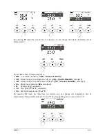
fig. 1-a

: Display of the measurement using the 

Pt100 SICRAM probe 

fig. 1-b

: Display of the measurement using the 

combined humidity/temperature SICRAM probe 

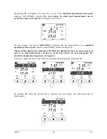
fig. 1-c

: Display of the measurement using the 

combined speed/temperature SICRAM probe 

fig. 1-d

: Display of the measurement using the 

photometric/radiometric SICRAM probe 

fig. 1-e

: Display of the measurement using the 

CO

2

 SICRAM probe 

fig. 1-f

: Display of the measurement using the 

CO SICRAM probe 

 
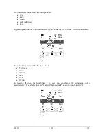
By pressing 

SHIFT FNC

, a drop-down menu is shown with the following information: 


unit

:


allows selection  of measuring unit for the actual  variable. 


data: 

Allows display of the maximum, minimum, and average values. 


section: 

Allows setting the pipeline section for flow rate calculation


Cal CO2

: allows starting of calibration procedure for the CO

2

 probe. 


Cal CO

: allows starting of calibration procedure for the CO probe and sensor change. 


4.3.1  Setting the pipeline section 

Proceed as follows to access 

section 

function: 


Use 

SHIFT FNC

 to open the drop-down menu; 


Use the arrow keys 

▲▼

 to select 

section


Press 

ENTER

 to confirm; 


The Shortcut menu will appear:


Use the 

▲▼


navigation keys to select 

section 

and press 

enter

.


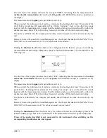
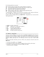
The following screen will 

appear:


Use the 

◄►


navigation keys to highlight the digit in the section. Use the 

▲▼


navigation 

keys to modify the highlighted digit. 

The area comprised must be between 0.0001 m

2

 (1 cm

2

) and 1.9999 m

2

.


Press 

◄►


to

select 

the digit  

Press 

▲▼


to


modify

 the digit  

Summary of Contents for HD32.1

Page 1: ...Operating manual Thermal Microclimate HD32 1 www deltaohm com English Keep for future reference Companies Brands of GHM...

Page 2: ...ANALYSIS 26 4 1 1 DR Index Draught Risk 27 4 1 2 WBGT Index 28 4 1 3 WCI Index 29 4 1 4 Radiation Temperature Tr 29 4 1 5 The unit of measurement Unit 29 4 1 6 The maximum minimum and average values...

Page 3: ...xide concentration 94 7 SERIAL INTERFACE AND USB 96 7 1 THE OPERATING PROGRAM A MICROCLIMATE ANALYSIS 96 7 2 THE OPERATING PROGRAM B DISCOMFORT ANALYSIS 98 7 3 THE OPERATING PROGRAM C PHYSICAL QUANTIT...

Page 4: ...Analysis operating program The machine can be programmed to perform the logging capture of a measurement session You can specifically set a sampling interval per each session Furthermore the auto star...

Page 5: ...can simultaneously detect the following physical quantities Temperature Relative humidity Illuminance luminance PAR irradiance Wind speed carbon monoxide concentration CO carbon dioxide concentration...

Page 6: ...HD32 1 6 V2 1 Thermal Microclimate HD32 1...

Page 7: ...nu confirms the data entered 7 ESC key Allows exiting from the menu or in case of a submenu exiting from the current level display 8 Navigation keys Allows navigation through the menus 9 PRINT key Sta...

Page 8: ...urements performed with the probes connected the instrument can directly calculate and display the following well being data WBGT index Tu index WCI index Average radiation temperature tr 2 1 1 WBGT I...

Page 9: ...TEMPERATURE OF 38 C FOR THE PEOPLE BEING EXAMINED In order to calculate the WBGT index the following probes should be connected The natural ventilation wet bulb temperature probe The globe thermomete...

Page 10: ...m the ground the formula is corrected as follows WCI 13 12 0 6215 ta 11 37 1 5 v1 5 0 16 0 4275 ta 1 5 v1 5 0 16 where v1 5 is the wind speed measured by the instrument at 1 5 m from the ground The fo...

Page 11: ...exchange with a man the same thermal radiation power exchanged in the real environment In order to evaluate the average radiation temperature you have to measure The globe thermometer temperature the...

Page 12: ...air temperature or even lower These conditions mainly in buildings with large window surfaces are not particularly healthy as the warm humid air facilitates the development of pathogenic organisms Fr...

Page 13: ...symmetry 2 2 1 Unsatisfied with the vertical difference of temperature By detecting the temperatures at various heights you can check the presence of a air temperature vertical gradient This gradient...

Page 14: ...the PDf index unsatisfied with the floor temperature you should refer to the following regulations ISO 7730 2 2 3 Unsatisfied with the radiant asymmetry The radiant temperature asymmetry tpr is the di...

Page 15: ...n order to calculate the percentage of the unsatisfied with the radiant asymmetry you should refer to the following regulations ISO 7730 2 3 THE OPERATING PROGRAM C PHYSICAL QUANTITIES The HD32 1 Ther...

Page 16: ...D32 1 main display is divided in three areas The first area displays the battery s charge status and the current time on the first line and the measured quantities arranged on two columns Tnw natural...

Page 17: ...ing to ISO 7730 The third area displays the F1 F2 and F3 options Please see the SHIFT FNC key in the following paragraph 3 1 3 The Operating Program C Physical Quantities Display The Thermal Microclim...

Page 18: ...e available units are C and F by pressing F1 again you can return to C By pressing F3 with next on the last line you go to the combined humidity temperature probe complete with SICRAM module The first...

Page 19: ...ogram of dry air g Kg Specific Humidity calculated AH Grams of vapor in a cubic meter of dry air g m3 Absolute Humidity calculated Pa Partial vapor pressure hPa calculated H Enthalpy J g calculated Td...

Page 20: ...urements of a combined speed temperature probe complete with SICRAM module are displayed The second line displays the wind speed The third line displays the flow rate measurement In order to get this...

Page 21: ...line is selected you can change the flow rate unit of measurement The units of measurement for the flow rate are l s liter s m3 s m3 min m3 h ft3 s ft3 min By pressing F1 when the fourth line is selec...

Page 22: ...select one of the rows with F2 key and then press repeatedly F1 The available units of measurement depend on the type of probe Type of measurement Unit of Measurement Illuminance Phot lux fcd Irradia...

Page 23: ...module The visualization is the following one The first line of the display indicates the symbol CO indicating that the measurement of carbon monoxide concentration detected by the CO probe with SICRA...

Page 24: ...and hour minutes seconds in the first line for about 8 seconds Normally the display shows on the left the icon for the battery s charge status on the right hour minutes seconds The battery symbol beco...

Page 25: ...key Allows exiting from the menu or in case of a submenu exiting from the current level display MEM key Allows starting and ending a logging session the data sending interval must be set in the menu...

Page 26: ...If you connect multiple probes of the same type only the first recognized probe is accepted the first two if light probes The probes scanning starts fro input 1 to input 8 The barometric pressure sen...

Page 27: ...risk wbgt WBGT index wet bulb globe temperature wci WCI index wind chill index trad average radiation temperature Tr unit temperature measurement unit data maximum medium average values 4 1 1 DR Index...

Page 28: ...t and the turbulence intensity value will be displayed 4 1 2 WBGT Index To display the WBGT index proceed as follows after opening the drop down menu with SHIFT FNC 4 Use the arrow keys to select WBGT...

Page 29: ...lsius F Fahrenheit or K Kelvin degrees as follows 1 Use SHIFT FNC to open the drop down menu 2 Use the arrow keys to select unit 3 Press ENTER to confirm the selected quantity is displayed in the cent...

Page 30: ...for further details 4 1 8 Start of a new logging session Press MEM to start a Logging session This key starts and stops the logging of a data block to be saved in the instrument s internal memory The...

Page 31: ...1 m Tf Temperature at floor level P Net radiation DT Radiant asymmetry temperature By pressing SHIFT FNC a drop down menu is shown with the following information unit allows selection of the unit of...

Page 32: ...isplay using F1 or F2 The F3 key allows choosing to clear Clr the maximum minimum and average data of the captured measurements In order to clear the data select Clr with F3 Another drop down menu wil...

Page 33: ...s display of the maximum minimum and average values section Allows setting the pipeline section for flow rate calculation Cal CO2 allows starting of calibration procedure for the CO2 probe Cal CO allo...

Page 34: ...wn menu Use the arrow keys to select data Press ENTER to confirm the selected quantity is displayed in the central line of the display The three quantities max maximum min minimum and avg average are...

Page 35: ...n menu by pressing SETUP press and ENTER to access the Info menu The following information on the instrument will be displayed Instrument code and operating program firmware date and version serial nu...

Page 36: ...Use the arrow keys to select the interval duration from 15 seconds to one hour 2 Press ENTER to confirm and return to the Logging menu 3 Press ESC to return to the Logging menu without making any chan...

Page 37: ...nd will turn off immediately afterwards thus increasing the battery life Once you have accessed the LOGGING submenu previous par use the arrow keys to select Self shut_off mode If the set Log Interval...

Page 38: ...op time The following message Enter start time will be displayed 1 Use the arrow keys to select the data to be changed year month day and hour minutes seconds 2 Once selected the data will start blink...

Page 39: ...To cancel the automatic start setting use the Cancel auto start function as illustrated in the following paragraph NOTE The automatic logging session is started even when the instrument is off If it i...

Page 40: ...ogs the instrument allows printing the files of the captured data Print selected log and deleting all memory Erase ALL logs The instrument can store up to 64 LOG sessions numbered progressively from 0...

Page 41: ...the page of the log to be printed will be displayed 1 Use the arrow keys to select the log to be printed press F1 and F3 to go to another page 2 once you select a file the acquisition start date and t...

Page 42: ...directly 5 3 SERIAL MENU SERIAL COMMUNICATION The Serial submenu allows setting the data transfer speed via serial port Baud rate and the record printing interval Print Interval The LOG sessions can b...

Page 43: ...s ESC to cancel the change and exit the menu item 5 Press ESC over and over to exit from the submenus 6 Press SETUP to exit immediately from the main menu WARNING The communication between instrument...

Page 44: ...enter the Reset submenu in order to carry out a complete reset of the instrument proceed as follows 1 Press SETUP 2 Use the arrow keys to select Reset 3 Press ENTER You will get the following message...

Page 45: ...get the following display 5 Use the arrow keys to select the operating program that you want to install 6 Press ENTER to confirm and wait for the chosen program self installation 7 At the end the ins...

Page 46: ...0 seconds 5 8 CALIBRATE The Calibrate menu is reserved to Technical Support It reports the calibrations and the last calibration performed To access the Calibrate submenu proceed as follows 1 Press SE...

Page 47: ...strument using the KEY LOCK function and start the LOG session in order to prevent any undesired access by unauthorized personnel To unlock the instrument repeat the steps above Enter the main menu an...

Page 48: ...cancel 7 The following message will appear 8 Use the arrow keys to enter the new password 9 Press ENTER to confirm or ESC to cancel and go back to the main menu 10 Press SETUP to exit the main menu d...

Page 49: ...lysis B Discomfort Analysis TP3207 Temperature probe Sensor type Thin film Pt100 Measurement uncertainty Class 1 3 DIN Measurement range 40 C 100 C Connection 4 wires plus SICRAM module Connector 8 po...

Page 50: ...150 mm according to ISO 7243 ISO 7726 Sensor type Pt100 Measurement uncertainty Class 1 3 DIN Measurement range 10 C 100 C Connection 4 wires plus SICRAM module Connector 8 pole female DIN45326 Cable...

Page 51: ...hermometer probe 50 mm Sensor type Pt100 Measurement uncertainty Class 1 3 DIN Measurement range 10 C 100 C Connection 4 wires plus SICRAM module Connector 8 pole female DIN45326 Cable length 2 meters...

Page 52: ...ers Upper probe T95 15 minutes Lower probe T95 4 minutes The TP3227K probe can be used for simultaneous measurement of temperature at 1 10 m and 0 10 m In order to perform simultaneous measurements at...

Page 53: ...perature measurement at floor level and at ankle height 0 10 m The TP3227PC has priority on the TP3227 1 if both are connected Sensor type Thin film Pt100 Measurement uncertainty Class 1 3 DIN Measure...

Page 54: ...al discomfort measurement due to vertical temperature gradient Sensor type Thin film Pt100 Measurement uncertainty Class 1 3 DIN Measurement range 10 C 100 C Connection 4 wires plus SICRAM module Conn...

Page 55: ...with the radiant asymmetry percentage Sensor type Pyranometer NTC Measurement uncertainty NTC 0 15 Typical spectral sensitivity 10 V W m2 Measurement range 0 C 60 C Connection 4 wires plus SICRAM modu...

Page 56: ...t wire probe Sensor type NTC 10Kohm Measurement uncertainty 0 2 m s 0 1 1 m s 0 3 m s 1 5 m s Measurement range 0 1 5 m s 0 C 80 C AP3203 30 C 30 C AP3203 F Connection 7 wires plus SICRAM module Conne...

Page 57: ...Sensor type Pt100 Measurement uncertainty Class A Measurement range 4 C 80 C Connection 4 wires plus SICRAM module Connector 8 pole female DIN45326 Cable length 2 meters Cotton wick length 16 cm Tank...

Page 58: ...indicated below Remove the sensor cap the cap is not screwed Insert the cotton wick previously dipped with distilled water into the temperature probe The cotton wick must protrude from the probe for a...

Page 59: ...n film Pt100 for temperature Capacity sensor for relative humidity Measurement uncertainty Temperature 1 3 DIN Relative humidity 2 5 Measurement range Temperature 40 C 100 C Relative humidity 0 100 RH...

Page 60: ...ype Pt100 Measurement uncertainty Class A Measurement range Natural wet Dry temperature 4 C 80 C 30 C 100 C Connection 7 wires plus 2 input SICRAM module Connector 8 pole female DIN45326 Cable length...

Page 61: ...e 0 5000ppm Resolution 1ppm Connector 8 female poles DIN45326 Cable length 2 metres Response Time T63 2 minutes Temperature Effect 0 2 C CO2 Typical value Atmospheric pressure effect Compensated with...

Page 62: ...e Usually 5 years in normal environment conditions Long term stability 5 of the measurement year Typical value Calibration At one point on 0ppm Work Relative Temperature Humidity 5 50 C 0 95 RH no con...

Page 63: ...complete with clamp and fastening screw to support the probes AM32 Rod complete with 2 clamps and fastening screws to support the probes LP 32 F R Support bracket for photometric radiometric probes f...

Page 64: ...te with head that can host up to 6 measurement probes The same tripod can be used to support the measurement instrument during data capture The arms fitted with suitable clamps for the measurement pro...

Page 65: ...o come into contact with live parts above 48V This could be extremely dangerous for the instrument as well as for the operator who could be electrocuted Avoid taking measurements in presence of high f...

Page 66: ...bulb temperature measurement HP3217DM The commissioning is carried out as follows Remove the cover it is not screwed on Insert the braid in the temperature probe the braid has been previously wet with...

Page 67: ...module The probes are detected during turn on and this cannot be performed when the instrument is already on therefore if a probe is connected and the instrument is on it is necessary to turn it off...

Page 68: ...sion 50 C 300 C TP473P I Penetration 50 C 400 C TP473P O Penetration 50 C 300 C TP474C O Contact 50 C 300 C TP475A O Air 50 C 250 C TP472I 5 Penetration 50 C 400 C TP472I 10 Penetration 50 C 400 C 0 1...

Page 69: ...g Grams of vapor in a kilogram of dry air g m3 Grams of vapor in a cubic meter of dry air hPa Partial vapor pressure hPa J g Enthalpy Td Dew point C or F Tw Wet bulb temperature C or F A measurement i...

Page 70: ...100 RH 40 150 C 1 5 0 85 RH 2 5 85 100 RH T 15 35 C 2 1 5 measure T remaining range 0 3 C Common characteristics Relative humidity Sensor Capacitive Resolution 0 1 RH Temperature drift 20 C 0 02 RH C...

Page 71: ...0 27 32 78 0 16 75 29 0 12 30 11 28 0 24 32 44 0 14 75 09 0 11 35 11 25 0 22 32 05 0 13 74 87 0 12 40 11 21 0 21 31 60 0 13 74 68 0 13 45 11 16 0 21 31 10 0 13 74 52 0 16 50 11 10 0 22 30 54 0 14 74...

Page 72: ...series On request the probes of the AP471 series can be fitted with a telescopic rod that eases measurements in areas difficult to reach for example vents The typical applications are wind speed and f...

Page 73: ...vigation keys to modify the highlighted digit The area comprised must be between 0 0001 m2 1 cm2 and 1 9999 m2 Pressing F1 toggles the display between m2 and inch2 Press Enter to confirm the informati...

Page 74: ...ure the environment temperature in the range 25 C 80 C the AP471 S4 probe in the range 0 C 80 C The AP472 S modules are calibrated in the factory no calibration is required by the user AP471 S1 AP471...

Page 75: ...nsor and introduce the probe in the air flow being measured maintaining the arrow at the top of the probe parallel to the flow as indicated in the figures The probe should be maintained orthogonal to...

Page 76: ...1 m s Air temperature compensation 0 80 C Care and maintenance of the probes The speed sensor of the AP471 S probes is heated and in the presence of gas vapors could trigger a fire or explosion Do not...

Page 77: ...HD32 1 77 V2 1 Dimensions 85 87 200 min 880 max 13 8 AP471 S1 110 13 8 AP471 S2 85 87 102 200 min 880 max 13 8 AP471 S3 Flexible Part...

Page 78: ...HD32 1 78 V2 1 MIN 350 MAX 1020 120 AP471 S4...

Page 79: ...S2 0 5 20 25 80 60 Greater diameters are suitable for flow measurements in the presence of turbulence with medium low air speeds i e at the exit of the ducts Lower diameters are suitable in applicati...

Page 80: ...easurement following the instructions provided in this chapter Care and maintenance of the probes The probe performance mainly at low speeds largely depends on the very slow friction of the vane on it...

Page 81: ...HD32 1 81 V2 1 Dimensions AP472 S1 AP472 S2 Unscrew the handle 3 holding the probe body still in the point 1...

Page 82: ...opic rod AP471S1 23 7 5 6 2 9 Technical information on Vane wind speed measurement probes using SICRAM module AP472 S1 AP472 S2 Type of Measurements Air velocity calculated flow air temperature Air ve...

Page 83: ...o the input It is sufficient to connect it If the instrument is already on turn it off and back on again in order for the probe to be detected The unit of measurement is determined according to the pr...

Page 84: ...6 T temperature coefficient 0 05 K Drift after 1 year 1 Working temperature 0 50 C Reference Standard CIE No 69 UNI 11142 LUMINANCE measurement probe LP 471 LUM 2 complete with SICRAM module and equip...

Page 85: ...2000 10000 Resolution mol m2 s 0 01 0 1 1 Spectral range 400nm 700nm Calibration uncertainty 5 f2 response according to the cosine law 6 f3 linearity 1 f4 instrument reading error 1digit f5 fatigue 0...

Page 86: ...00 0 1999 9 Resolution W m2 0 1 10 3 0 001 0 01 0 1 Spectral range 400nm 1050nm Calibration uncertainty 5 f2 response according to the cosine law 6 f3 linearity 1 f4 instrument reading error 1digit f5...

Page 87: ...999 9 Resolution W m2 0 1 10 3 0 001 0 01 0 1 Spectral range 315nm 400nm Peak 360nm Calibration uncertainty 5 f2 response according to the cosine law 6 f3 linearity 1 f4 instrument reading error 1digi...

Page 88: ...Resolution W m2 0 1 10 3 0 001 0 01 0 1 Spectral range 280nm 315nm Peak 305nm Calibration uncertainty 5 f2 response according to the cosine law 6 f3 linearity 2 f4 instrument reading error 1digit f5 f...

Page 89: ...Resolution W m2 0 1 10 3 0 001 0 01 0 1 Spectral range 220nm 280nm Peak 260nm Calibration uncertainty 5 f2 response according to the cosine law 6 f3 linearity 1 f4 instrument reading error 1digit f5 f...

Page 90: ...ality in internal environments and detecting any loss of CO The sensor for the measurement of CO consists of an electro chemical cell with two electrodes CO probe calibration The probe is calibrated b...

Page 91: ...nd visualized Calibration completed message Press F2 Exit for coming to the measurement 8 The process is finished Zero CO calibration with nitrogen cylinder code MINICAN 12A 1 Switch the instrument on...

Page 92: ...ration completed message Close the cylinder tap and remove the CO sensor cowling 9 Press F2 Exit for coming back to calibrate 10 Insert the protection 11 The process is finished Replacement of CO sens...

Page 93: ...ensitivity and confirm with ENTER The screen for the replacement of CO sensor appears 9 With Up and Down arrows set the sensor sensibility value Press ENTER to confirm the instrument comes back to the...

Page 94: ...pm The calibration has to be done on one point each new calibration cancels the previous one The concentration of carbon dioxide in air is influenced by different factors the human activities companie...

Page 95: ...ation without modifying the working conditions 8 If the timer reaches the zero the instrument gives an acoustic signal out that confirms that the calibration is finished Note the instrument rejects th...

Page 96: ...PC the RS232 serial port is automatically disabled and vice versa The instruments are provided with a complete set of commands and data queries to be sent via the PC All the commands transferred to th...

Page 97: ...time Tw Tg Ta Pr RH Va Tr WBGT i WBGT o WCI LN A00 A01 B02 B03 Print instrument memory map If a section is allocated a number is displayed if it is free 2 points are displayed LFn Log n 0 started on 2...

Page 98: ...9 5 C Print temperature at head height H1 Tb 22 0 C Print temperature at body height H2 Tn 21 6 C Print temperature of the net radiometer H3 Tk 19 5 C Print temperature at ankles height H4 Tf 19 5 C P...

Page 99: ...libration date C4 Probe 4 type serial number calibration date C5 Probe 5 type serial number calibration date C6 Probe 6 type serial number calibration date C7 Probe 7 type serial number calibration da...

Page 100: ...wer off function DISABLE WC0 Setting SELF off WC1 Setting SELF on RA Sample print 0sec Reading of PRINT interval set RL Sample log 30sec Reading of LOG interval set WA Setting PRINT interval is a hexa...

Page 101: ...instrument or on the PC 7 4 2 The Erase Function clearing the memory To clear the memory use the Erase Log function see par 5 2 5 Log File Manager The instrument starts clearing the internal memory at...

Page 102: ...esent or is faulty OVFL Overflow appears when the probe detects a value that exceeds the expected measurement range UFL Underflow appears when the probe detects a lower value than the expected measure...

Page 103: ...correct measurement and turns off Data stored on memory will remain The battery symbol becomes when the external power supply is connected To replace the batteries proceed as follows 1 Switch the ins...

Page 104: ...mpletely then reinsert the batteries 9 1 WARNING ABOUT BATTERY USE Batteries should be removed when the instrument is not used for an extended time Flat batteries must be replaced immediately Avoid lo...

Page 105: ...1 105 V2 1 11 MEASUREMENT REPORTS PRINTING Please find below a few examples of reports created with DeltaLog10 software for the different environments 12 1 MODERATE ENVIRONMENT Norm ISO 7730 Norm ISO...

Page 106: ...HD32 1 106 V2 1 Moderate Environment Norm ISO 7730...

Page 107: ...HD32 1 107 V2 1 Moderate Environment Norm ISO 7730...

Page 108: ...HD32 1 108 V2 1 Moderate Environment Norm ISO 7730...

Page 109: ...HD32 1 109 V2 1 Moderate Environment Norm ISO 7730...

Page 110: ...HD32 1 110 V2 1 Moderate Environment Norm ISO 7730...

Page 111: ...HD32 1 111 V2 1 Moderate Environment Norm ISO 7730...

Page 112: ...HD32 1 112 V2 1 12 2 WARM ENVIRONMENT Norm ISO 7243 Norm ISO 7243...

Page 113: ...HD32 1 113 V2 1 Warm Environment Norm ISO 7243...

Page 114: ...HD32 1 114 V2 1 Warm Environment Norm ISO 7243 Norm ISO 7243...

Page 115: ...HD32 1 115 V2 1 Warm Environment Norm ISO 7243...

Page 116: ...HD32 1 116 V2 1 Warm Environment Norm ISO 7243...

Page 117: ...HD32 1 117 V2 1 Warm Environment Norm ISO 7243...

Page 118: ...HD32 1 118 V2 1 12 3 DISCOMFORT ANALYSIS Norm ISO 7730 Norm ISO 7730...

Page 119: ...HD32 1 119 V2 1 Discomfort Analysis Norm ISO 7730...

Page 120: ...HD32 1 120 V2 1 Discomfort Analysis Norm ISO 7730...

Page 121: ...HD32 1 121 V2 1 Discomfort Analysis Norm ISO 7730...

Page 122: ...HD32 1 122 V2 1 Discomfort Analysis Norm ISO 7730...

Page 123: ...HD32 1 123 V2 1 Discomfort Analysis Norm ISO 7730...

Page 124: ...HD32 1 124 V2 1 Discomfort Analysis Norm ISO 7730...

Page 125: ...HD32 1 125 V2 1 12 4 HOT ENVIRONMENT Norm ISO 7933 Norm ISO 7933...

Page 126: ...HD32 1 126 V2 1 Hot Environment Norm ISO 7933...

Page 127: ...HD32 1 127 V2 1 Hot Environment Norm ISO 7933...

Page 128: ...HD32 1 128 V2 1 Hot Environment Norm ISO 7933...

Page 129: ...HD32 1 129 V2 1 Hot Environment Norm ISO 7933...

Page 130: ...HD32 1 130 V2 1 Hot Environment Norm ISO 7933...

Page 131: ...HD32 1 131 V2 1 Hot Environment Norm ISO 7933...

Page 132: ...HD32 1 132 V2 1 12 5 COLD ENVIRONMENT Norm ISO 11079 Norm ISO 11079...

Page 133: ...HD32 1 133 V2 1 Cold Environment Norm ISO 11079...

Page 134: ...HD32 1 134 V2 1 Cold Environment Norm ISO 11079...

Page 135: ...HD32 1 135 V2 1 Cold Environment Norm ISO 11079...

Page 136: ...HD32 1 136 V2 1 Cold Environment Norm ISO 11079...

Page 137: ...HD32 1 137 V2 1 Cold Environment Norm ISO 11079...

Page 138: ...HD32 1 138 V2 1 Cold Environment Norm ISO 11079...

Page 139: ...HD32 1 139 V2 1 Cold Environment Norm ISO 11079...

Page 140: ...HD32 1 140 V2 1 12 6 PHYSICAL QUANTITIES...

Page 141: ...ime 1s Instrument temperature measurement with Pt100 probe Pt100 measuring range 200 650 C Resolution 0 01 C in the range 199 99 C 0 1 C in the remaining range Accuracy 0 01 C in the range 199 99 C 0...

Page 142: ...400 baud Data bit 8 Parity None Stop bit 1 Flow Control Xon Xoff Serial cable length Max 15 m USB interface Type 1 1 2 0 electrically isolated Memory divided into 64 blocks Memory capacity 67600 recor...

Page 143: ...Heat Flow PHS Predicted Heat Strain Model Severe Hot ISO 7243 DeltaLog10 Cold Environments Prog A IREQ Required Insulation DLE Limit Exposure Time RT Limit Exposure Time WCI Wind Chill Index Severe Co...

Page 144: ...3217DM Two sensor probe for natural ventilation wet bulb temperature and dry bulb temperature measurement instead of HP3201 TP3204S and TP3207 The following table shows the required probes for microcl...

Page 145: ...Temperature WBGT Outdoor Wet Bulb and Globe Thermometer Temperature with solar radiation SWp Sweat Rate Ep Predicted Evaporative Heat Flow 1 Tre Water Loss Dlim tre Dlimloss50 Dlimloss95 PHS _________...

Page 146: ...body surface and the naked human body surface Skin average temperature Wet skin fraction Unit convective thermal conductivity Unit radiation thermal conductivity Water partial pressure at environment...

Page 147: ...e measurement net radiometer In the following table are reported the required probes for microclimate indexes measurement The following indexes are calculated using the DeltaLog10 Discomfort Analysis...

Page 148: ...nloadable from Delta OHM website operating manual Probes support carrying case and cables must be ordered separately Accessories VTRAP32 Tripod complete with 6 input head and 5 probe holders code HD32...

Page 149: ...standalone temperature probes Pt100 sensor one for floor level temperature measurement 70 mm height 30 mm the other for temperature measurement at ankle height 3 mm height 100 mm Cable length 2 meters...

Page 150: ...ith 50 cc of distilled water 14 2 PROBES FOR THE OPERATING PROGRAM C PHYSICAL QUANTITIES 14 2 1 Temperature probes complete with SICRAM module TP472I Pt100 sensor immersion probe Stem 3 mm length 300...

Page 151: ...rectional hot wire telescopic probe with base measuring range 0 1 5m s Cable length 2 meters VANE PROBES AP472 S1 Vane probe with thermocouple K 100 mm Speed from 0 6 to 25 m s temperature from 25 to...

Page 152: ...5000ppm Cable L 2m MINICAN 12A Nitrogen cylinder for CO2 calibration at 0ppm Volume 20 litres With adjusting valve MINICAN 12A1 Nitrogen cylinder for CO2 calibration at 0ppm Volume 20 litres Without...

Page 153: ...HD32 1 153 V2 1 NOTES...

Page 154: ...HD32 1 154 V2 1 NOTES...

Page 155: ......

Page 156: ...zed third parties is excluded from the guarantee The instrument shall be returned FREE OF SHIPMENT CHARGES to your dealer The jurisdiction of Padua applies in any dispute The electrical and electronic...

Page 157: ...e result of the constant development of the product This may produce some differences between the information written in this manual and the instrument you have purchased We cannot completely exclude...

Page 158: ...GHM GROUP Delta OHM Delta Ohm S r l a socio unico Via Marconi 5 35030 Caselle di Selvazzano Padova ITALY Phone 39 049 8977150 Fax 39 049 635596 www deltaohm com info deltaohm com V2 1 11 01 2019...

Reviews: