background image

4


2. 

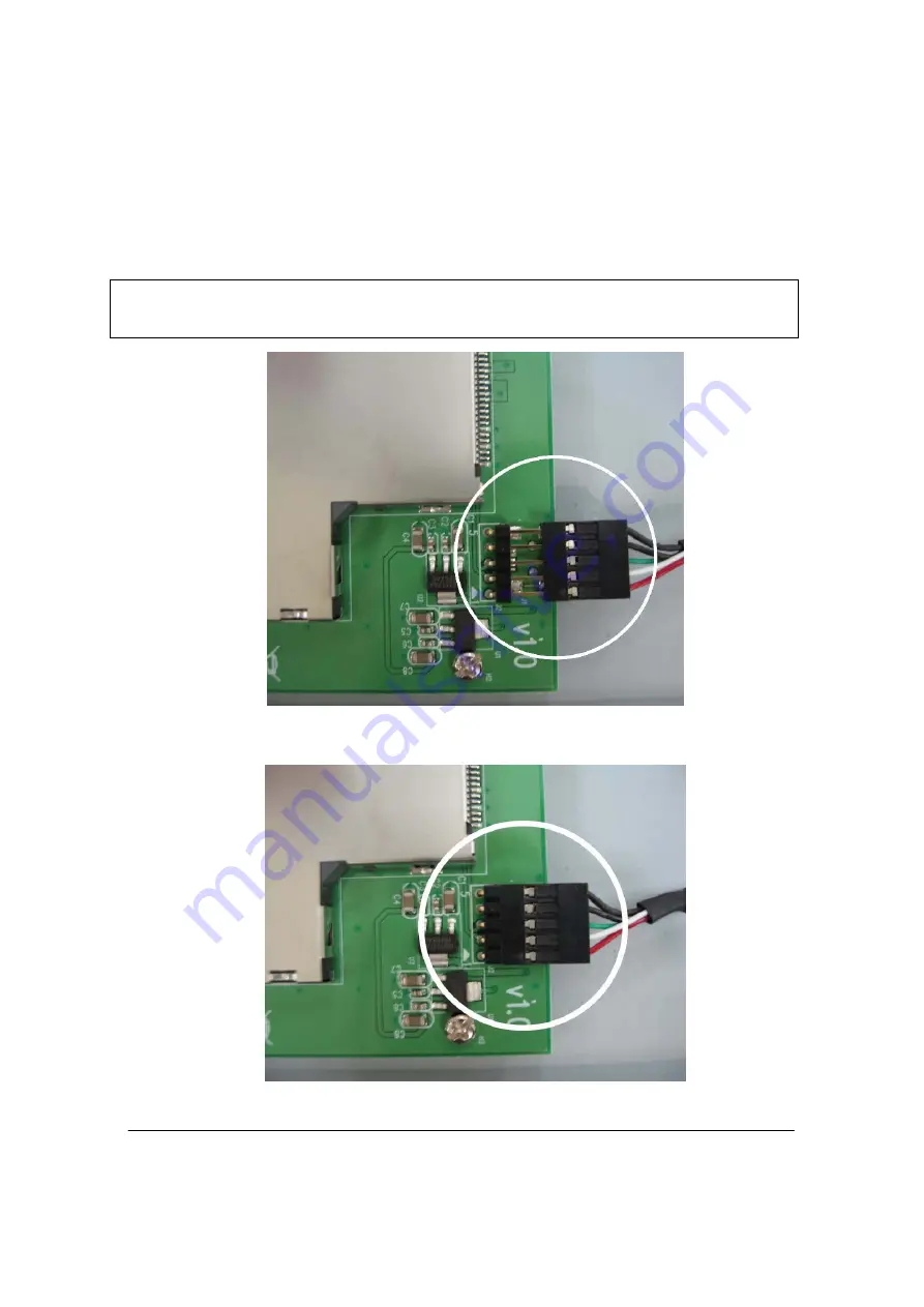
Unpack the package of USB 5-pin cable and take the cable out. Please 

refer to the following images and make sure the correct cable 
connection. 


Note: Wrong cable connection will make serious damage   
to the product.   


The connecting direction of USB 5-pin cable   


After USB 5-pin cable connection   

Summary of Contents for SX-174

Page 1: ...B 2 0 based ExpressCard interface into various types of desktop computer Works with various types of USB 2 0 based EV DO 3G or HSDPA 3 5G broadband ExpressCard PC Cards through USB 2 0 port 1 2 System...

Page 2: ...B cable definition USB to ExpressCard Bay layout USB 5 pin cable image Wire color Signal Pin 1 Red 5VDC Pin 2 White DATA Pin 3 Green DATA Pin 4 Black Ground Pin 5 Black Ground USB 5 pin cable wiring c...

Page 3: ...uring the installation please follow the guidelines below Discharge any static electricity build up in your body by touching a large grounded metal surface or the computer case if plugged in for a few...

Page 4: ...take the cable out Please refer to the following images and make sure the correct cable connection Note Wrong cable connection will make serious damage to the product The connecting direction of USB...

Page 5: ...the USB to ExpressCard Bay remove the cover plate from the selected drive bay Secure the USB to ExpressCard to the drive bay by using the supplied holding screw set 7 Select an available USB 2 0 port...

Page 6: ...6 8 Make sure the pin 1 position of the USB 5 pin port Please refer to the following images and make sure the correct cable connection Connecting USB 5 pin cable to your motherboard...

Page 7: ...before system boot up Refer to the user s manual of your motherboard 10 Insert your ExpressCard into this USB to ExpressCard Bay every time before you start the system Otherwise your system may not su...

Page 8: ...8 5303 0315 001...

Reviews: