background image

- 5 - 

ƒ

 Hardware Operation 

When users want to startup TP04G-AL/AL2, a 24VDC power is needed. After applying 
24VDC power to TP04G-AL/AL2, it will enter into the startup display and then enter the 
user-designed program. Pressing Esc key and holding on for 5 seconds can return to 
communication transmission window. Users can upload or download programs through 
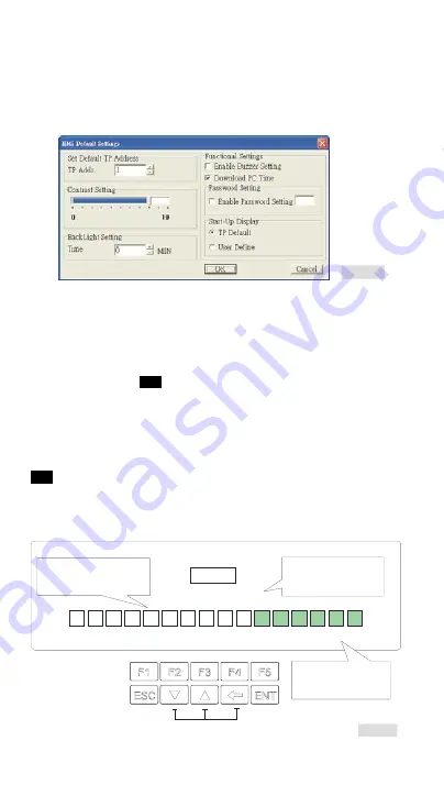
TPEditor software program. The options used to determine the settings of 
TP04G-AL/AL2 in TPEditor software program are described as below. 

F igur e8


1.  Contrast Setting: Adjust the contrast of LCM display screen. 

2.  Backlight Setting: Adjust the automatic turn-off time of LCM. Setting range is 0~99 

seconds. If the value is set to 0, the LCM backlight will not turn off. 

3.  Enable Buzzer Setting: Set the buzzer mode as Normal mode (Buzzer enabled) or 

Quiet mode (Buzzer disabled). 

4.  Password Setting: Set up password function as Enable/Disable. If the password is 

enabled, it will require users to input a password before entering any system menu. 
The default setting is 

1234

5.  Start-up Display: Select the start-up display as TP Default or User Define. If User 

Define is selected, users can download the user defined start-up display designed by 
TPEditor. 

ƒ

 Password Function 

If users forgot the password, the password can be cleared by using the following code: 

8888

. This universal code will clear the password as well as all TP04G-AL/AL2 internal 

programs. The TP04G-AL/AL2 will be reset to the factory settings. Care should be taken 
when using it. The password can be the alphabet from A to F or the number from 0 to 9. 
For entering the password characters, function keys F0~F5 must be applied. Please 
refer to the figure below. 

<

<-

< <-

1234

F1

F5

F2

F3

Select

F4

2

1

3

4

5

6

8

7

9

0

A

B

C

D

E

F

<

<-

< <-

Password

Enter the number 

or the 

 according 

to 

the format of the passwor d

.


0~9 

alphabet A~ F 

(deci mal or hexadeci mal)


Functions of these three keys are disabled 

while entering  password.  


F1  and  F5 are used as a 
direction key to move the 
cursor to the desi red di gi t
of the password.
  

F1  and  F4 are used as 
a direction key to move 
the cursor t o the desi red
number or alphabet.
  

Figure9


Call 1(800)985-6929 for Sales

deltaacdrives.com

[email protected]

Call 1(800)985-6929 for Sales

deltaacdrives.com

[email protected]

Summary of Contents for TP04G-AL

Page 1: ...2009 02 26 5011683500 4L00 TP 1143130 01 Call 1 800 985 6929 for Sales deltaacdrives com sales deltaacdrives com Call 1 800 985 6929 for Sales deltaacdrives com sales deltaacdrives com...

Page 2: ...ll the wiring again before switching on the power a DO NOT touch any terminal when the power is switched on DO NOT touch any internal circuit in 1 minute after the power is switched off a Make sure th...

Page 3: ...creen type Display color STN LCD Monochromatic Driver Only for Delta automation products For automation products of Delta and other manufacturers Function Numeric keys F1 F5 ESC Enter and Up Down Keys...

Page 4: ...ator Green When the power is connected to the product LED will be ON Display area LCM display area It is used to display current program status Users can re define its function through operation in us...

Page 5: ...ion please insert TP04G AL AL2 to the opening hole on the panel then tighten the screws If firmer mounting is required please use the mounting fixed supports and screws in the accessory package which...

Page 6: ...up Display Select the start up display as TP Default or User Define If User Define is selected users can download the user defined start up display designed by TPEditor Password Function If users for...

Page 7: ...13 14 1 5 6 9 25 PIN D SUB 9 PIN D SUB TO PLC MINI DIN TERMINAL Figure12 2 DVPACAB2A30 DVPACAB2B10 TO PC or TP04G AL AL2 1 5 6 9 9 PIN D SUB TO PLC MINI DIN TERMINAL Figure13 TO PC or TP04G AL AL2 1 5...

Page 8: ...Figure20 Tx Rx Tx Rx Rx Tx 1 3 SG Tx GND COM1 Port RS 422 y Switch between RS 422 RS 485 by using 8 PIN DIP switch 8 PIN DIP switch RS 485 RS 422 SW1 SW4 On Off SW5 SW8 Off On Battery Life and Precisi...

Page 9: ...S 232 RS 422 RS 485 DC RS 485 RS 422 AL2 3 PIN 6 PIN 12 24 AWG 4 12 lb inch y Figure3 y Figure4 y Figure5 Call 1 800 985 6929 for Sales deltaacdrives com sales deltaacdrives com Call 1 800 985 6929 fo...

Page 10: ...38 8 8 8 24 8 8 12 24 5 8 16 24 4 RS 232 COM1 RS 232 7 8 bits 1 2 bits 9 600bps 115 200bps RS 232 9 PIN D SUB RS 422 COM2 RS 485 COM2 RS 485 RS 422 7 8 bits 1 2 bits 9 600bps 115 200bps RS 422 9 PIN...

Page 11: ...8 4Hz f 150Hz 1 0g IEC61131 2 IEC 68 2 27 TEST Ea 15g 11 X Y Z 3 18 RF CISPR11 Class A 30 230MHz 40dB uV m 230MHz 1GHz 47dB uV m RF EN61000 4 3 80 2000MHz 10V m EN61000 4 2 8KV 4KV EN61000 4 4 1KV I...

Page 12: ...AL AL2 1 LCM 2 LED 0 99 0 LED 3 4 1234 5 TP TPEditor TP TP 8888 TP TP 0 9 A F F1 F5 1234 F1 F5 F2 F3 Select F4 2 1 3 4 5 6 8 7 9 0 A B C D E F F2 F4 F1 F5 10 16 0 9 A F Call 1 800 985 6929 for Sales...

Page 13: ...AL AL2 9 PIN D SUB PIN 1 RS 232 Figure17 2 RS 422 Figure18 3 DVPACAB630 RS 422 Figure19 Figure20 y RS 422 RS 485 8PIN 8 PIN RS 485 RS 422 SW1 SW4 On Off SW5 SW8 Off On y C 20 0 20 60 2 0 2 5 2 7 2 8...

Page 14: ...a a a y y RS 232 RS 422 RS 485 DC RS485 RS 422 AL2 3 PIN 6 PIN 12 24 AWG 4 12 lb inch y Figure3 y Figure4 y Figure5 Call 1 800 985 6929 for Sales deltaacdrives com sales deltaacdrives com Call 1 800 9...

Page 15: ...8 38 8 8 8 24 8 8 12 24 5 8 16 24 4 RS 232 COM1 RS 232 7 8 bits 1 2 bits 9 600bps 115 200bps RS 232 9 PIN D SUB RS 422 COM2 RS 485 COM2 RS 485 RS 422 7 8 bits 1 2 bits 9 600bps 115 200bps RS 422 9 PIN...

Page 16: ...1 0g IEC61131 2 IEC 68 2 27 TEST Ea 15g 11 X Y Z 3 18 RF CISPR11 Class A 30 230MHz 40dB uV m 230MHz 1GHz 47dB uV m RF EN61000 4 3 80 2000MHz 10V m EN61000 4 2 8KV 4KV EN61000 4 4 1KV I O 500V 268g 270...

Page 17: ...AL AL2 1 LCM 2 LED 0 99 0 LED 3 4 1234 5 TP TPEditor TP TP 8888 TP TP 0 9 A F F1 F5 1234 F1 F5 F2 F3 Select F4 2 1 3 4 5 6 8 7 9 0 A B C D E F F2 F4 F1 F5 10 16 0 9 A F Call 1 800 985 6929 for Sales...

Page 18: ...AL AL2 9 PIN D SUB PIN 1 RS 232 Figure17 2 RS 422 Figure18 3 DVPACAB630 RS 422 Figure19 Figure20 y RS 422 RS 485 8 PIN 8 PIN RS 485 RS 422 SW1 SW4 On Off SW5 SW8 Off On y C 20 0 20 60 2 0 2 5 2 7 2 8...

Reviews: