


RTU-ECAT Operation Manual
5-2
5
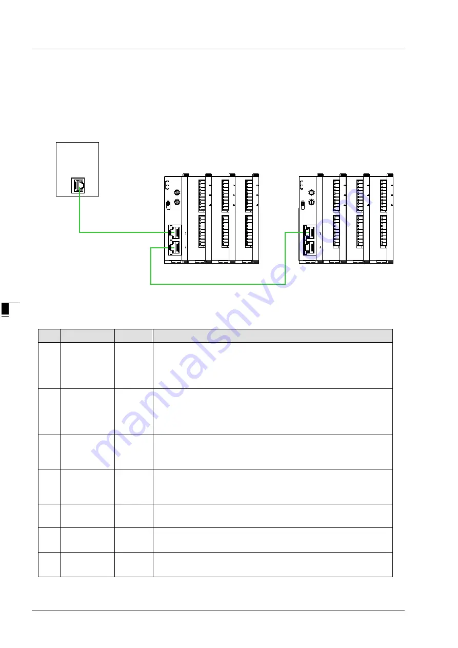
This section describes how RTU-ECAT as an EtherCAT slave realizes the data exchange between EtherCAT
master and DVP-S series extension modules.
EtherCAT master transmits the data to extension modules.
The input data from extension modules are transmitted back to EtherCAT master.
DV
P-
04
AD
DV
P-
04
DA
DV
P-
16
SP
N
OD
E
AD
D
RE
SS
x1 0
x1 0
1
0
5
4
3
2
1
0
9
8
7
6
5
4
3
2
1
0
9
8
7
6
RTU- ECAT
P OW ER
R UN
A LA R M
R U N
S TO P
Eth
erC
AT
IN
O
U
T
EtherCAT
Master
DV
P-
04
AD
DV
P-
04
DA
DV
P-
16
SP
NO
D
E
AD
D
RE
SS
x10
x10
1
0
5
4
3
2
1
0
9
8
7
6
5
4
3
2
1
0
9
8
7
6
RTU- ECAT
PO W ER
RU N
AL A RM
R U N
ST O P
Eth
erC
AT
IN
O
U
T
EtherCAT
EtherCAT
5.1
Terms
No.
Name
Unit
Explanation
1
Control word
Word
Sets the mode of RTU-ECAT. When the content of the control word
is 8000Hex, RTU-ECAT is in STOP state. When the content of the
control word is 8001Hex, RTU-ECAT is in RUN state.
See section 6.3 for more details on the control word.
2
Status
Word
Status includes Error register (for error information), LV state (for
voltage status), Error module number (for right-side module number)
and Error list (for extension module errors)
See section 6.3 for more details.
3
Digital input
points
Bit
The number of digital input points is a multiple of 8. The number is
regarded as 8 when it is less than 8 and as 16 when it is greater than
8 but less than 16.
4
Digital output
points
Bit
The number of digital output points is a multiple of 8. The number is
regarded as 8 when it is less than 8 and as 16 when it is greater than
8 but less than 16.
5
Special module
number
Unit
Number of special modules connected to RTU-ECAT
Range: 0~8
6
Input
data length
Word
The total length of input data of special modules on the right of
RTU-ECAT
7
Output
data length
Word
The total length of output data of special modules on the right of
RTU-ECAT


