background image

20

ADJUSTING CUTTINGHEAD
PARALLEL TO TABLE

The cuttinghead is set parallel to the table at the factory
and no further adjustment should be necessary. If your
machine is planing a taper, first check to see if the knives
are set properly in the cutterhead. Then check to see if
the cuttinghead is set parallel to the table as follows:

DISCONNECT MACHINE FROM POWER

SOURCE

.

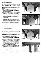
1. Place gage block (A) Fig. 49, on table directly under

front edge of head casting (B) as shown. Lower 
head casting until front edge of head casting (B) just
touches the top of the gage block.

2.

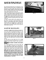
Move gage block (A) Fig. 50, to opposite end of 
table, as shown. Distance from table to edge of 
head casting should be the same.

3.

Repeat 

STEPS 2

and 

3

on outfeed end of table.

4.

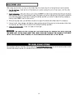
If head casting is not parallel to table, tilt planer on 
its side as shown in Fig. 51. Remove bolt (C) and 
loosen bolt (D) Fig. 51, which will allow you to move
the idler sprocket assembly (E) far enough to release
tension on chain as shown in Fig. 52. Remove chain
from sprocket on end of head casting that must be
adjusted. In this case chain has been removed from
sprocket (F).

5.

Turn sprocket (F) Fig. 52, by hand to bring that 
corner into adjustment with the other three 
corners. 

IMPORTANT: THIS ADJUSTMENT IS 

VERY SENSITIVE AND IT SHOULD NOT BE 
NECESSARY TO TURN THE SPROCKET MORE 
THAN ONE OR TWO TEETH

. Turning sprocket (F) 

clockwise will decrease the distance between the 
table and head casting. Counterclockwise will 
increase the distance.

6.

Replace chain being careful not to disturb the 
position of the sprockets and replace idler sprocket
assembly (E) Fig. 51.

Fig. 49

Fig. 50

Fig. 51

Fig. 52

B

A

A

C

D

E

F

Summary of Contents for 22-680

Page 1: ...07 30 04 Copyright 2004 Delta Machinery To learn more about DELTA MACHINERY visit our website at www deltamachinery com For Parts Service Warranty or other Assistance please call 1 800 223 7278 In Canada call 1 800 463 3582 Shown with Delta Model 50 654 Accessory Planer Stand and Roller Extension Tables ...

Page 2: ...at www deltamachinery com Postal Mail Technical Service Manager Delta Machinery 4825 Highway 45 North Jackson TN 38305 Information regarding the safe and proper operation of this tool is available from the following sources Power Tool Institute 1300 Sumner Avenue Cleveland OH 44115 2851 www powertoolinstitute org National Safety Council 1121 Spring Lake Drive Itasca IL 60143 3201 American National...

Page 3: ...LEMS The symbols below are used to help you recognize this information SAFETY GUIDELINES DEFINITIONS SOME DUST CREATED BY POWER SANDING SAWING GRINDING DRILLING AND OTHER CONSTRUCTION ACTIVITIES contains chemicals known to cause cancer birth defects or other reproductive harm Some examples of these chemicals are lead from lead based paints crystalline silica from bricks and cement and other masonr...

Page 4: ...RDS Check to see that all guards are in place secured and working correctly to prevent injury 11 REMOVE ADJUSTING KEYS AND WRENCHES BEFORE STARTING THE MACHINE Tools scrap pieces and other debris can be thrown at high speed causing injury 12 USE THE RIGHT MACHINE Don t force a machine or an attachment to do a job for which it was not designed Damage to the machine and or injury may result 13 USE R...

Page 5: ... into the knives 13 DO NOT STAND IN LINE OF THE WORKPIECE Kickback can cause injury 14 ALLOWTHECUTTERHEADTOREACHFULLSPEED before feeding a workpiece Changing speeds while planing can cause kickback 15 WHEN PLANING BOWED STOCK place the concave cup down side of the stock on the table and cut with the grain to prevent kickback 16 DO NOT FEED A WORKPIECE that is warped contains knots or is embedded w...

Page 6: ...Y GROUNDED IF YOU ARE NOT SURE HAVE A QUALIFIED ELECTRICIAN CHECK THE RECEPTACLE POWER CONNECTIONS MOTOR SPECIFICATIONS The motor supplied with your 15 Planer is either a three horsepower single phase motor or a three horsepower three phase motor The three horsepower single phase motor is wired for 230 Volt operation and the three horsepower three phase motor is wired for 200 220 Volt operation Be...

Page 7: ...81mm width 6 165mm thickness and 1 8 5mm depth of cut NOTICE THE PHOTO ON THE MANUAL COVER ILLUSTRATES THE CURRENT PRODUCTION MODEL ALL OTHER ILLUSTRATIONS CONTAINED IN THE MANUAL ARE REPRESENTATIVE ONLY AND MAY NOT DEPICT THE ACTUAL COLOR LABELING OR ACCESSORIES AND ARE INTENDED TO ILLUSTRATE TECHNIQUE ONLY Fig B 200 220 VOLT THREE PHASE OPERATION If the motor on your machine is wired for 200 220...

Page 8: ...e the section LIFTING THE MACHINE Figure 3 Illustrates the loose items supplied with your machine Fig 2 Fig 3 1 2 4 12 11 13 14 15 16 18 17 10 9 8 7 6 5 3 1 Top cover 2 M6 x 16mm hex flange screw 4 for fastening top cover to machine 3 Cord clamp 4 Knife setting gage 5 Raising and lowering handwheel 6 Key for raising and lowering handwheel 7 Decal for raising and lowering handwheel 8 M10 flat washe...

Page 9: ...nd lowering handwheel B clockwise and insert two 6 or 8 foot long 2 x 4 s C between the cuttinghead and table as shown Lower the cuttinghead just until it touches the 2 x 4 s C Fig 10 so that they are positioned solidly between the table and cuttinghead Then with two people on each end of the 2 x 4 s move the machine to its desired location Fig 10 C A B 6 Loosen two head locking knobs one of which...

Page 10: ...ed to the motor and is to be fastened to the planer as follows Fig 10A 1 Line up the two holes A Fig 10A in the switch bracket C with the two threaded holes B in the left front of the machine Fig 10B 2 Fasten the switch bracket C Fig 10B to the planer using the two screws and flat washers D as shown B B C C D A A ...

Page 11: ...sixteen carriage bolts B and nuts are used to mount the front rear and side tie bars to the legs The two side tie bars F are 20 15 16 long and the front and rear tie bars D are 23 7 16 long 2 IMPORTANT When lifting the planer to position it on a stand or bench refer to the following section LIFTING THE MACHINE 3 The front end of the top shelf is indicated in Fig 11 Two slots G which are supplied o...

Page 12: ...se machine the switch is located on the left front side of the planer head assembly as shown in Fig 19A To turn the machine ON press the start button C and to turn the machine OFF press the stop button D C D Fig 19A OVERLOAD PROTECTION Three Phase Machine Only The three phase machine is provided with overload protection which will shut off the motor if the planer is overloaded or if line voltage f...

Page 13: ...EED CONTROL CHANGE SPEEDS ONLY WHILE THE MOTOR IS RUNNING DO NOT CHANGE SPEEDS WHILE PLANING Two feed roll speeds of 16 and 30 feet per minute are provided with your planer Generally speaking the slower feed rate provides more cuts per inch thus a finer smoother finish of the workpiece is obtained A good rule to follow would be to operate the machine at the faster feed rate for general planing and...

Page 14: ... are free of gum and pitch and that they move independently and operate correctly Fig 27 ADJUSTING BELT TENSION DISCONNECT MACHINE FROM POWER SOURCE 1 Remove four screws A Fig 28 and remove the belt and pulley guard cover B 2 Place a 2 x 4 D Fig 29 between the motor plate and the top of the head casting as shown 3 Loosen the four screws C Fig 29 and pry up on motor plate until correct belt tension...

Page 15: ...ining two knives in the same manner C To adjust the knife that must be reset loosen all five locking screws two of which are shown at K Fig 37 by turning them clockwise into the lock bar Then using the wrench supplied turn allen screw L Fig 37 counterclockwise to lower or clockwise to raise the knife on each end of the cutterhead until the cutting edge of knife H Fig 36 just touches the bottom of ...

Page 16: ...in the cutterhead Back out the locking screws two of which are shown at K Fig 37 just enough to hold all three knives in the cutterhead D Adjust all three knives as explained under STEP 4 6 IMPORTANT After knives have been adjusted re place chip deflector that was removed in STEP 3 top cover that was removed in STEP 1 and return motor assembly to the upright position The motor assembly was pivoted...

Page 17: ...39 on the table directly under the cutterhead as shown Using a 0 020 feeler gage B placed on top of the gage block raise or lower the head assembly until one of the knives just touches the feeler gage when the knife is at its lowest point Then lock the head assembly in this position 3 Place the gage block A Fig 40 minus the feeler gage under one end of the chipbreaker C as shown The bottom of the ...

Page 18: ...nut D 5 Repeat this adjustment with the gage block on the opposite end of the infeed roller Fig 42 Fig 43 Fig 44 Fig 45 ADJUSTING HEIGHT OF OUTFEED ROLLER The outfeed roller is adjusted at the factory to be 0 040 below the cutting circle To check and adjust the height of the outfeed roller proceed as follows DISCONNECT MACHINE FROM POWER SOURCE 1 Make sure the knives are adjusted properly as expla...

Page 19: ...ith two table rollers A Fig 47 which aid in feeding the stock by reducing friction and turn as the stock is fed through the planer It is not possible to give exact dimensions on the proper height setting of the table rollers because each type of wood behaves differently As a general rule however when planing rough stock the table rollers should be set HIGH 0 003 to 0 005 above the table surface an...

Page 20: ...tfeed end of table 4 If head casting is not parallel to table tilt planer on its side as shown in Fig 51 Remove bolt C and loosen bolt D Fig 51 which will allow you to move the idler sprocket assembly E far enough to release tension on chain as shown in Fig 52 Remove chain from sprocket on end of head casting that must be adjusted In this case chain has been removed from sprocket F 5 Turn sprocket...

Page 21: ...ce 3 When planing long stock provide table extensions to support the infeed and outfeed end of the workpiece 4 For best results always engage cutterhead lock before planing plane with the grain only and keep planer table clean Occasionally wax table surface to reduce friction during the planing operation 5 Cross cut to Final Length Cross cut lumber to final length THE KNIVES ON THE PLANER WILL NOT...

Page 22: ...ll plastic parts should be cleaned with a soft damp cloth NEVER use solvents to clean plastic parts They could possibly dissolve or otherwise damage the material Wear ANSI Z87 1 safety glasses while using compressed air FAILURE TO START Should your machine fail to start check to make sure the prongs on the cord plug are making good contact in the outlet Also check for blown fuses or open circuit b...

Page 23: ...option any new Delta machine machine part or machine accessory which in normal use has proven to be defective in workmanship or material provided that the customer returns the product prepaid to a Delta factory service center or authorized service station with proof of purchase of the product within two years and provides Delta with reasonable opportunity to verify the alleged defect by inspection...

Page 24: ...ter Cable Delta más cercano ARIZONA Tempe 85282 Phoenix 2400 West Southern Avenue Suite 105 Phone 602 437 1200 Fax 602 437 2200 CALIFORNIA Ontario 91761 Los Angeles 3949A East Guasti Road Phone 909 390 5555 Fax 909 390 5554 San Diego 92111 7638 Clairemnot Blvd Phone 858 277 9595 Fax 858 277 9696 San Leandro 94577 Oakland 3039 Teagarden Street Phone 510 357 9762 Fax 510 357 7939 COLORADO Arvada 800...

Reviews: