background image

10

OPERATIONAL CONTROLS AND ADJUSTMENTS

8.

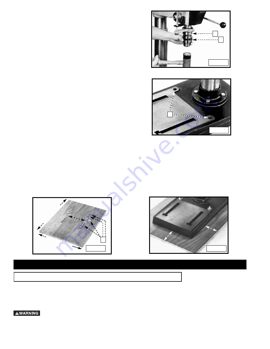
Open the chuck jaws as wide as possible by turning chuck
sleeve (T) Fig. 8. Hold the chuck (S) Fig. 8 and carefully drive
and seat it (S) on the spindle with a rubber mallet or with a
block of wood and hammer.

IMPORTANT:

To avoid damage to the chuck, do not drive the

chuck with a metal hammer.

9.

The drill press is shipped from the factory with the belts on the
pulleys. 

NOTE: Properly tension the belts before use. Refer to section

“CHANGING SPINDLE SPEEDS AND ADJUSTING BELT
TENSION”

.

T

S

MOUNTING DRILL PRESS ON A SUPPORTING SURFACE

Fig. 8

Fig. 9

S

MOUNTING THE DRILL PRESS ON A
PLYWOOD BASE

If you do not fasten your machine permanently, then you must fasten the drill press to a plywood mounting board to prevent
it from tipping over. Use a good grade of 3/4" or thicker plywood. 

DO NOT

make the mounting board from particle board.

1.

Start with a 21" x 28" or larger piece of plywood. Drill two 3/8" diameter holes (B) Fig. 11 that match the mounting holes
(S) Fig. 9 of the drill press base.

2.

Fasten the drill press base to the mounting board using the carriage bolts, flat washers, lockwashers, and hex nuts
(C) Fig. 10, furnished with your drill press. The holes for the carriage bolt heads and flat washers under the board
must be countersunk so that the bolt heads are flush or below the bottom surface of the board. Make sure to use
a flat washer, lock washer and hex nut above the drill press base.

3.

The supporting board must extend a minimum of 3" beyond each edge of the drill press base (Fig. 11).

4.

Secure the plywood base to the floor or supporting surface if the drill press has any tendency to vibrate, slide, or walk
during normal operation.

Fig. 11

3" Min.

3" Min.

OPERATION

If, during operation, the machine has a tendency to tip over, slide,
or walk on the supporting surface, secure the machine base to
the supporting surface with an M8x1.25x125mm carriage head
screw, 8.5mm flat washer, 8.5mm lock washer, M8x1.25 hex nut
through the two holes (S) Fig. 9 located in the machine base.

1.

The on/off switches (A and B) Fig. 12 are located on the front of the drill press. To turn the machine 

“ON”,

depress the

“ON” 

switch.

2.

To turn the machine 

“OFF”,

depress the 

“OFF” 

switch.

Make sure that the switch is in the “OFF” position before plugging in the power cord. In the event of a
power failure, 

depress the 

“OFF” 

switch.

An accidental start-up can cause injury.

STARTING AND STOPPING THE DRILL PRESS

28" MINIMUM

21" MINIMUM

C

Fig. 10

Summary of Contents for 17-965

Page 1: ...lta Machinery ESPA OL P GINA 17 To learn more about DELTA MACHINERY visit our website at www deltamachinery com For Parts Service Warranty or other Assistance please call 1 800 223 7278 In Canada call...

Page 2: ...Mail Technical Service Manager Delta Machinery 4825 Highway 45 North Jackson TN 38305 IN CANADA 505 SOUTHGATE DRIVE GUELPH ONTARIO N1H 6M7 Information regarding the safe and proper operation of this t...

Page 3: ...EMS The symbols below are used to help you recognize this information SAFETY GUIDELINES DEFINITIONS SOME DUST CREATED BY POWER SANDING SAWING GRINDING DRILLING AND OTHER CONSTRUCTION ACTIVITIES contai...

Page 4: ...to the machine and or injury may result 13 USE RECOMMENDED ACCESSORIES The use of accessories and attachments not recommended by Delta may cause damage to the machine or injury to the user 14 USE THE...

Page 5: ...ne and or serious injury 13 AVOID AWKWARD OPERATIONS AND HAND POSITIONS A sudden slip could cause a hand to move into the bit 14 KEEP ARMS HANDS AND FINGERS away from the bit Serious injury to the han...

Page 6: ...ith a metal screw NOTE In Canada the use of a temporary adapter is not permitted by the Canadian Electric Code 1 All grounded cord connected machines In the event of a malfunction or breakdown groundi...

Page 7: ...be sure to use one heavy enough to carry the current of the machine An undersized cord will cause a drop in line voltage resulting in loss of power and overheating Fig D 1 or D 2 shows the correct ga...

Page 8: ...olor labeling or accessories and are intended to illustrate technique only CARTON CONTENTS The Delta Model 17 965 is a 16 1 2 floor model drill press This heavy duty machine has a 3 4 HP 120 240V indu...

Page 9: ...table G Fig 4 with the base of the drill press and tighten the locking lever K and set screw L with the supplied hex wrench M 5 Thread the three pinion shaft handles N Fig 6 into the three holes in t...

Page 10: ...and hex nuts C Fig 10 furnished with your drill press The holes for the carriage bolt heads and flat washers under the board must be countersunk so that the bolt heads are flush or below the bottom s...

Page 11: ...al position to allow the gears to mesh and prevent slippage 2 To rotate the table A Fig 14 on the table bracket loosen the lock handle D 3 To tilt the table right or left pull out and remove the table...

Page 12: ...nut A Fig 20 on the threaded stop rod B B G A F D E C DRILLING HOLES TO DEPTH DISCONNECT MACHINE FROM POWER SOURCE Fig 20 NOTE Twelve spindle speeds are available on the drill press A belt positioning...

Page 13: ...M POWER SOURCE Fig 21 Fig 22 A B D A B C Raise and lower the spindle with the pinion handles A Fig 23 You can lock the quill B Fig 23 at any point in its travel by tightening locking lever C NOTE The...

Page 14: ...ottom hole and are designed for removal of wood chips Do not use hand bits which have a screw tip At drill press speeds they will lift and rotate the workpiece For through boring align the workpiece s...

Page 15: ...ir passages with dry compressed air All plastic parts should be cleaned with a soft damp cloth NEVER use solvents to clean plastic parts They could possibly dissolve or otherwise damage the material W...

Page 16: ...Delta may require that electric motors be returned prepaid to a motor manufacturer s authorized station for inspection and repair or replacement Delta will not be responsible for any asserted defect...

Page 17: ...F brica Porter Cable Delta m s cercano ARIZONA Phoenix 85013 2906 4501 N 7th Ave Phone 602 279 6414 Fax 602 279 5470 CALIFORNIA Ontario 91761 Los Angeles 3949A East Guasti Road Phone 909 390 5555 Fax...

Reviews: