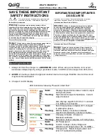
Remote LED
(Optional)
Installation Instructions
WARNING: The output of chargers with greater than 48V may
pose an energy and/or shock hazard under normal use. These
units must be installed in the host equipment in such a manner
that the output cable and battery connections are only
accessible with the use of a tool by qualified personnel.
Mounting:
1) Mount the charger with adequate ventilation. Ideally it
will be mounted horizontally with airflow from below. If it
will be mounted vertically, it is recommended that the
DC-output cord be at the higher end of the charger.
2) Keep the charger free of oil, dirt, mud, or dust to keep
the cooling fins operating as efficiently as possible.
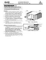
3) Mount the charger by the mounting plate using
appropriate fasteners. (ie. locking ¼” or M6 bolts)
4) For UL2202 compliance, a 12AWG green bonding wire
must be attached from the stud located on the charger
(see Figure 1) to the vehicle frame.
5) Install such that risk of human contact with hot surfaces
is reduced.
6) The charger’s AC plug must be located at least 18”
above the ground and the display visible to the user.
DC Battery Connection Procedure:
1) The green wire outputs battery voltage when the charger
is not plugged into AC to provide an interlock function
(see Figure 2).
If used, a user-supplied 1A fast-blow external fuse
must be installed in-line to prevent damage.
Shorting or drawing more than 1A may damage
charger and void the warranty.
2) Securely fasten the black ring terminal to the negative
terminal ("-", or “NEG”) of the battery pack.
3) Check that the correct charge algorithm is being used
and change algorithm if necessary. Securely fasten the
red ring terminal to the positive terminal ("+", or "POS")
of the battery pack.
Installation Manual for:
QuiQ 912- 24xx / 36xx / 48xx / 72xx
Ground Stud
Figure 1: Charger Mounting
Figure 2: Charger Connections
GRN
B+
Interlock
Charger
Internal
Output
F1
NC
NO
F2
B-
BLK
RED
1A
WHT


