DELTA M Corporation
3242-OM-04 3/27/02
31
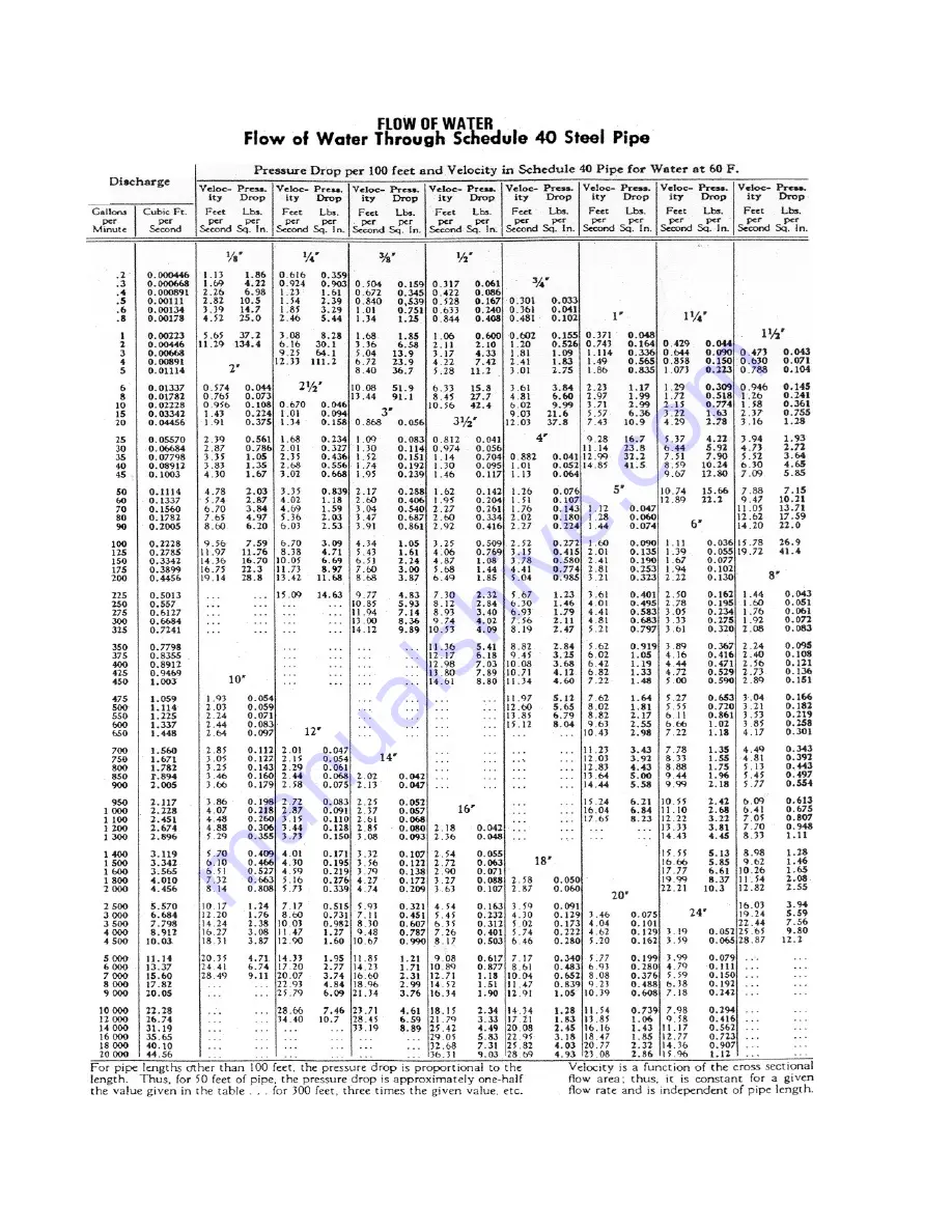
9.3 FLOW OF WATER THROUGH SCHEDULE 40 STEEL PIPE
9.4
MODEL NUMBER DESIGNATION AND AVAILABLE OPTIONS
Page 1: ...N THE DESIGN SALE MANUFACTURE TEST OR SUPPLY OF THE SAME OR SIMILAR PRODUCTS OPERATION AND MAINTENANCE MANUAL microtuf MODEL FS4200 SERIES MASS FLOW SWITCH MODEL LS3200 SERIES POINT LEVEL SWITCH DOCUM...
Page 2: ...ING DETECTED DUE TO THE PIPE THREAD MOUNTING IT MAY BE NECESSARY TO MAKE A TRIAL FIT ADD OR REMOVE TEFLON TAPE OR OTHER PIPE THREAD SEALANT AND REINSTALL TO ACHIEVE A SATISFACTORY SEAL WITH THE SENSOR...
Page 3: ...sformer configuration tag NOTICE This manual covers the following model numbers microtuf Series Models FS4200 LS3200 Agency Approvals Explosion Proof rating Mass Flow Switch Point Level Switch CENELEC...
Page 4: ...3 CALIBRATION FLOW 5 0 OPERATION AND CALIBRATION OF THE microtuf SWITCH FOR POINT LEVEL APPLICATIONS 5 1 PRE OPERATIONAL CHECKS 5 2 L E D AND RELAY STATUS LOGIC FAIL SAFE 5 3 CALIBRATION LEVEL 6 0 MAI...
Page 5: ...ated between the heated and reference RTD pair is a function of the density and or velocity of the media with which the sensor is in contact Other physical properties may have a secondary effect as we...
Page 6: ...5 MNPT 2 42 61 47 2 0 50 8 LENGTH 8 20 32 REF 6 1 154 94 REF STD INSERTION 3 875 98 42 STANDARD FITTING SEE FIGURE 5 75 19 05 FNPT FIELD WIRING CONNECTION DRAWING FILE MTF1A00 DWG FCW CORPORATION FIGU...
Page 7: ...0 32 REF 6 0 152 4 REF 5 20 132 08 REF 6 31 160 27 REF C L MOUNT STRAP OPTIONAL DRAWINGFILE MTF1B00 DWG FCW DIMENSIONS IN INCHES MILLIMETERS CORPORATION SEE FIGURE 5 FIGURE 1B LS3200 FS4200 microtuf O...
Page 8: ...cs of water will cool the heated RTD surface causing a decrease in the signal output This same rational applies for any two media in contact with the sensor Each medium will have its own characteristi...
Page 9: ...density but for simplicity FPS is used and density effects are ignored This is normally not critical for flow switching applications When the sensor is inserted into a liquid or gas the heated RTD is...
Page 10: ...DRAWING FILE MTF3A00 DWG FCW Figure 3 A shows a block diagram of the microtuf switch Once the switch is set to respond to the minimum and maximum flow rates or wet vs dry conditions the trip point is...
Page 11: ...VER VCC VCC 1 RTNS RTN 2 3 CS 4 C HS 5 H VCC COMPARATOR CURRENT SOURCES SENSORS EXCIT CURRENTS RETURN 9 10 PROBE ENCLOSURE POWER SUPPLY VCC SAFETY GROUND H N FILTERED POWER TEST POINTS TBA TBB 6 DRAWI...
Page 12: ...CAPTIVE SCREWS 2 PLACES TRANSFORMER FIELD WIRING TBB SENSORS WIRING TBA The instrument enclosure at the top of unit contains the microtuf Switch electronics board which is removable to access the ter...
Page 13: ...D SWITCH IF YOU HAVE A NON STANDARD SWITCH AN ALTERNATE SIZE WRENCH MAY BE REQUIRED DO NOT USE THE INSTRUMENT HEAD TO TIGHTEN THE SWITCH TO THE MOUNTING PORT ROTATION OF THE INSTRUMENT HEAD WITH RESPE...
Page 14: ...DELTA M Corporation 3242 OM 04 3 27 02 10 This page left blank intentionally...
Page 15: ...HORIZONTAL MOUNTING LEVEL APPLICATION VIEW B B VIEW A A FLOW APPLICATION VIEW C C C C FLOW NOTES THE ARROWS ON THE FLATS OF THE MOUNTING FITTING INDICATES 1 FOR FLOW APPLICATION THE DIRECTION OF FLOW...
Page 16: ...the transformer and pulling it straight out Connect power and alarm relay wiring to Terminal Block TBB as shown in Figure 6 0 Reinstall the microtuf Switch electronics and tighten the captive screws F...
Page 17: ...2 2 Remote Electronics RE Option For the remote electronics option mount the remote instrument head using two mounting wings or bracket provided Connect the switch wiring between the microtuf Switch...
Page 18: ...SAFETYGND WIRING CONNECTION DETAILS NOTE 4 REMOTE ELECTRONICS INSTRUMENT HEAD JUMPERS NOTE 1 1 2 3 4 5 6 REMOTE PROBE RELAY C NO NC N H C N O N C N C C N O POWER REL1 1 REL1 2 CAUTION FOR 10 DEG C ABO...
Page 19: ...DEPT MANAGER B 1003 LARSENDRIVE ECONUMBER APPROVED DIRECTORY FILE OAKRIDGE TN37830 DWG NO DATE PAGE ANDMAY CONTAININFORMATIONCOVEREDBY PATENTS AND OR CONSIDEREDCONFIDENTIAL UNLESS RIGHTS ARE EXPRESSLY...
Page 20: ...ower at its source 4 1 3 Observe that either the red or green LED comes on 4 1 4 If neither lamp illuminates refer to the trouble shooting Section 6 2 4 2 L E D and Relay Status Logic Fail safe 4 2 1...
Page 21: ...220 VAC 110 VAC 24 VDC 24 VAC SN PN200203 TRANSFORMER CORPORATION 2 2 3 3 1 1 FIGURE 8 0 microtuf SWITCH ELECTRONICS MTF800 FCW DWG 4 2 3 Alternate Operation Field Selectable The relay logic may be r...
Page 22: ...BE FLOW RESPONSE FOR THREE MEDIA AND DRAWING FILE MTF900 DWG FCW A B GREEN RED FUSE RELAY R13 H2 H1 N2 N1 R10 0 50 10 0 Q1 U1 U3 L1 R15 GND J1 TP3 TP2 U2 TP1 TP4 Q6 J2 T1 U4 LIQUIDS 0 001 0 10 0 01 1...
Page 23: ...nous constant and free of bubbles if a liquid NOTE The flow rate maximum should be at least 5 fps liquid or 500 fps gas if possible for best calibration 8 Set the trip adjust pot to 100 fully cw 9 Adj...
Page 24: ...re an indication of the sensors status ie dry or wet and are not affected by the position of the fail safe jumper J 2 The fail safe jumper J 2 changes the relay activation status allowing the user to...
Page 25: ...Dispersion Fluid o NO ie hydrocarbons o NC Wet or Higher Thermal OFF ON Activated Dispersion Fluid o NO ie water FIGURE 8 0 microtuf SWITCH ELECTRONICS MTF800 FCW DWG A A B B GREEN RED FUSE RELAY R13...
Page 26: ...CE DRAWING MTF1000 DWG FCW 0 100 50 SPAN ADJUSTMENT ZERO ADJUSTMENT VACUUM HYDROCARBON LIQUIDS WATER LIQUID METALS FLUIDS 0 0 SENSOR SIGNAL mV DECREASING THERMAL DISPERSION TRIP POINT POT SCALE TRIP P...
Page 27: ...l the switching point is well defined Leave the Red LED illuminated 8 Raise the level of the liquid to be detected until the probe sensor tips are submerged and wet covered 9 Set the trip adjust pot t...
Page 28: ...O NOT SANDBLAST OR ABRASIVE CLEAN THE SENSING PROBES THE SENSING PROBES COULD BE DAMAGED BY ABRASIVES 6 2 Troubleshooting 6 2 1 Power and Continuity Verification 1 Turn power off to the microtuf Switc...
Page 29: ...rotuf Switch 2 Allow a 5 minute cool down 3 Measure the resistance of each RTD at pins 1 and 6 of TBA see Figure 6 0 or 7 0 for the hot RTD and pins 3 and 5 of TBA for the cold RTD These resistances s...
Page 30: ...losure EEx d IIB T4 Killark Enclosure CE EMC Directive 89 336 EEC CE Option OPERATING TEMPERATURE Process 70 C to 200 C 100 F to 390 F standard to 600 C 1000 F optional Electronics 40 C to 60 C 40 F t...
Page 31: ...rmal use LIMITS AND EXCLUSIONS DELTA M CORPORATION SHALL NOT BE LIABLE FOR INCIDENTAL OR CONSEQUENTIAL DAMAGES INCLUDING BUT NOT LIMITED TO LOSS OF USE LOSS OF SALES OR INCONVENIENCE RESULTING FROM TH...
Page 32: ...FPS 1 667 E 02 Cubic In Per Minute CIPM CFPS 9 645 E 06 Milliliters Per Minute MLPM CFPS 5 886 E 07 Milliliters Per Second MLPS CFPS 3 531 E 05 Milliliters Per Hour MLPH CPFS 9 810 E 09 Liters Per Day...
Page 33: ...80 70 60 14 4 10 00 9 00 8 00 7 00 6 00 5 00 4 00 3 00 2 00 1 44 00264 0020 0010 00090 00080 00070 00060 00050 00040 00030 000264 3 82 3 0 2 0 1 00 90 80 70 60 50 382 0905 08 07 06 05 04 03 02 010 009...
Page 34: ...DELTA M Corporation 3242 OM 04 3 27 02 30 This page left blank intentionally...
Page 35: ...DELTA M Corporation 3242 OM 04 3 27 02 31 9 3 FLOW OF WATER THROUGH SCHEDULE 40 STEEL PIPE 9 4 MODEL NUMBER DESIGNATION AND AVAILABLE OPTIONS...
Page 36: ...O N TAG TH E 24 V A C S E LE C TI ON I S A S P E C I A L OR D E R REFERENCE APPROVAL AGENCIES Ex PROOF MODEL NUMBERS S M SPECIAL MATERIAL MT0080 MO DEL S MICRO TUF R SERIES MICROTUF SERIES R 0 7 5 0...
Page 37: ...3 0 0 INCH 7 6 2 2 0 0 INCH 5 0 8 2 MT MEDIUM TEMPERATURE SENSO R 3 0 0 C 5 7 2 F 1 1 0 1 1 0 VAC 2 2 0 VAC 2 0 0 IN MNPT 5 0 8 2 0 FL AT FACE FL G 3 0 0 L B RATING 0 A RAISED FACE FL G 1 5 0 L B RAT...
Page 38: ...2 NX FL O W SWITCH L S3 2 NX L EVEL SWITCH FS4 2 NX FL O W SWITCH L O CAL EL ECTRO NICS L E TH E LS 32N X FS 42N X S WI TC H FA MI LI E S I N P U T P OWE R I S FA C TOR Y S E T TO TH E P OWE R S LI S...
Page 39: ...NX REMO TE PRO BE ELECTRONICS MT0060 MICROTUF R SERIES A N I N S TRU ME N T I S N OT R A TE D E X P LOS I ON P R OOF N OR A GE N C Y A P P R OV E D P R ODU C T FA MI LY MOU N TI NG P R OC E S S FI TTI...