GENERAL
SM3300
10 / 30
DELTA ELEKTRONIKA B.V.
rev. Jan. 2022
4.18
PARALLEL OPERATION
The power supplies can be connected in parallel without
special precautions and limitations.
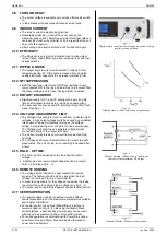
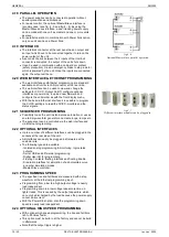
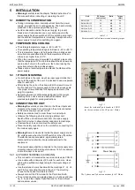
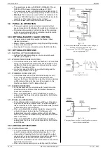
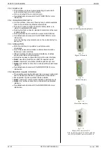
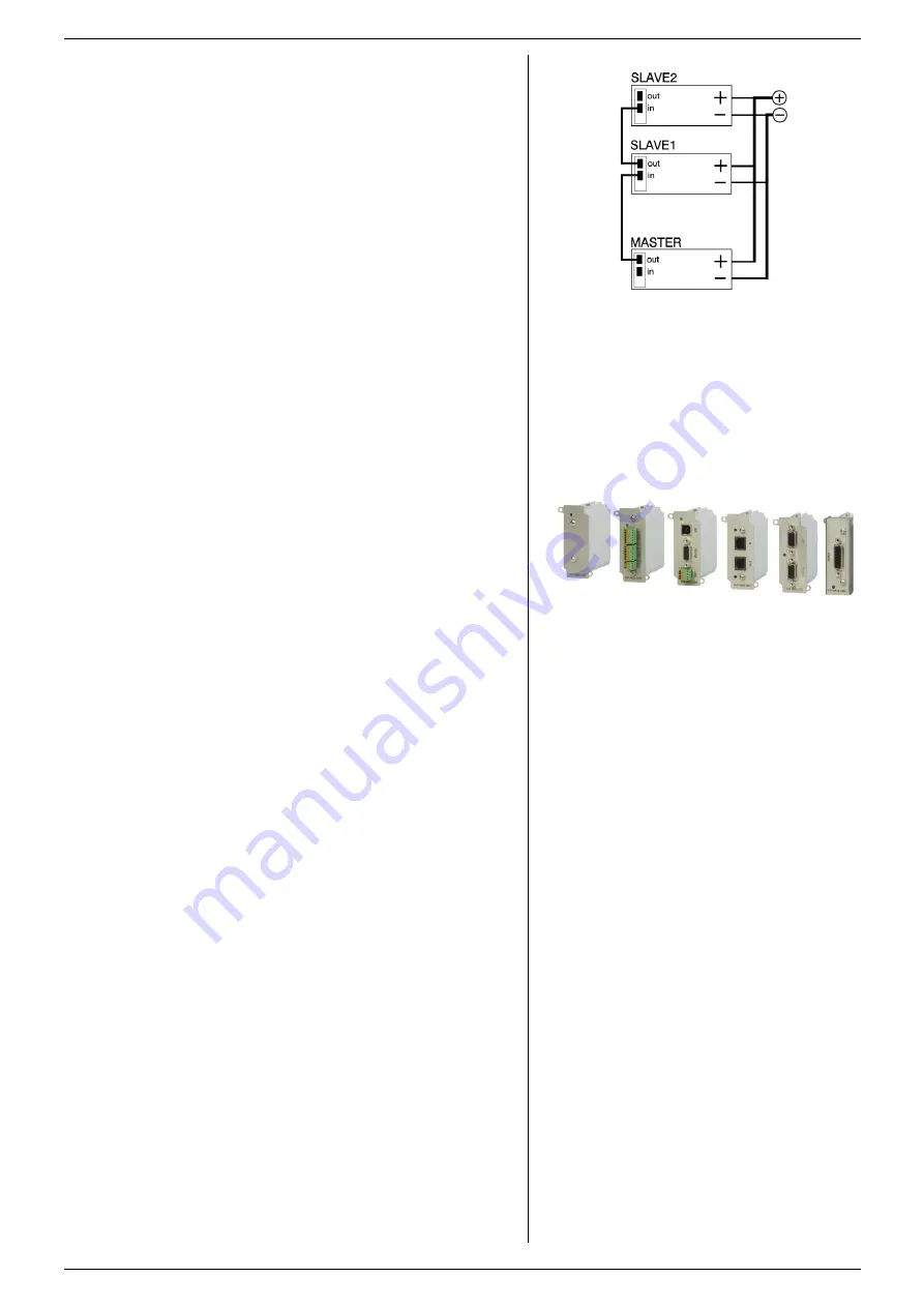
For easier control, the optional Master/Slave interface is
recommended (see fig. 4 - 5 and fig. 4 - 6). By using the
Master/Slave series interface, a dual tracking power supply
can be made with one unit as master and one or more units
as slave.
For parallel operation in combination with Power Sink option,
only one unit can have a Power Sink.
4.19
INTERLOCK
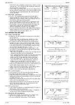
The Interlock connector at the rear panel has an output and
an input which have to be connected together to turn on the
power output of the unit.
As soon as the link between the 2 inputs of the Interlock
connector is disrupted, the output of the unit shuts down.
It can be used in combination with a cabinet door contact
(safety precaution) or as an emergency brake to stop a motor
which is powered by the unit. Once the inputs are connected
again, the output will be on.
4.20
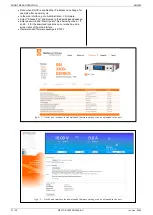
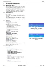
WEB INTERFACE & ETHERNET PROGRAMMING
The web interface and Ethernet programming are standard
available on all units via LAN connector at the rear side.
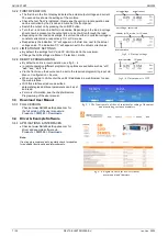
The web interface can be used to view and change the
settings for CV, CC, Output On/Off, configure optional
interfaces or power sink, to upload new firmware and
configure the unit similar as with the front display menu.
With the build-in Ethernet interface it is possible to program
the CV/CC-settings, to read the CV/CC-monitors and the
status signals.
4.21
SEQUENCER PROGRAMMING
Possibility to use the unit in stand-alone automation or use as
an arbitrary waveform generator and create loops, ramps etc.
The sequencer can be controlled via the web interface and
via Ethernet programming.
4.22
OPTIONAL INTERFACES
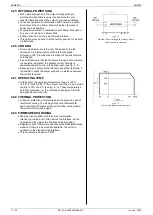
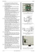
Up to a number of 4 different interfaces can be plugged in the
sockets at the rear side of the unit.
All interfaces can easily be plugged in afterwards at the
customer site.
The following types are available:
- Isolated analog programming & monitoring, logic status
outputs.
- Serial, USB and differential programming.
- Digital User I/O for programming.
- Floating Contacts, floating Interlock and floating Enable.
- Simulation interface for simulation of a photovoltaic curve
and other simulation modes.
- Master/Slave controller.
4.23
PROGRAMMING SPEED
The specified rise and fall times are measured with a step
waveform at the Ethernet programming input.
Programming from a low to a high output voltage is nearly
load independent.
Programming down to a low voltage takes more time on
lighter loads. This is caused by the output capacitors, which
can only be discharged by the load because the power supply
cannot sink current.
With the Power Sink option, also the programming down
speed is nearly load independent.
4.24
OPTIONAL HIGH SPEED PROGRAMMING
With optional high speed programming, the rise and fall time
is 5 to 25 times faster.
This option must be build in at the factory and cannot be build
in afterwards.
Note that the output ripple is higher.
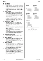
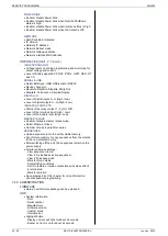
fig 4 - 7
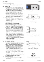
Different interface modules can be plugged in.
fig 4 - 6
Optional Master/slave parallel operation.


