


MAINTENANCE & CALIBRATION
SM6000
20 / 21
DELTA ELEKTRONIKA B.V.
rev. Nov. 2020
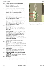
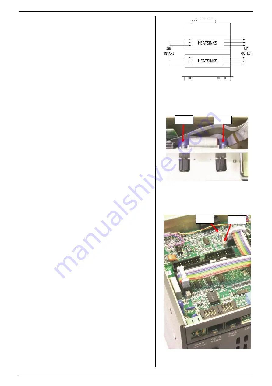
fig 6 -1
The fans are located at the left side and blow
through the tunnels.
6
MAINTENANCE & CALIBRATION
6.1
GENERAL
The SM-series power supplies do not need any maintenance
or calibration. However, care must be taken that the cooling
unit is not obstructed.
6.2
COOLING FANS
The internal construction of the power supply is such that no
dust will reach the sensitive control circuitry, only the heat
sinks in a tunnel will be cooled by forced air (see fig. 6 - 1)
The built up of dust on the impellers of the fans and the heat
sink fins depends on the environment. It is advised to inspect
the fans and heat sinks regularly.
Since the used fan type has an over-capacity, dust will not
present a problem very quickly.
The thermal protection will shutdown the output in case of
overheating, so no damage will be done to the power supply.
6.3
GALVANIC INDUSTRY
For using the power supplies in the galvanic industry it is
strongly recommended to take precautions against an
aggressive environment.
An aggressive environment with acid, salt, etc. can harm the
electronic components. Sometimes even the copper tracks on
the printed circuit boards dissolve.
To avoid problems, the power supplies should be mounted in
a relatively clean room, in a cabinet receiving clean air with
over pressure, or a cabinet with a heat exchanger.
6.4
CALIBRATION
The power supplies are factory calibrated and normally need
no further calibration.
After installation of a new or different interface, no calibration
is needed.
Only in special situations, for example after repairing a unit,
calibration can be necessary.
6.5
METER CALIBRATION
DIGITAL METERS
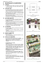
The full scale indication can be calibrated with R25_31 and
R25_36 on P596 (see fig. 6 - 2).
6.6
SPECIAL CALIBRATIONS
The following calibrations must be done by qualified
personnel only. Wrong calibration causes malfunction. These
calibrations are only needed after special repairs.
Warning !
Damage caused by wrong calibration is not
warranted.
CALIBRATING THE CURRENT
MONITOR OFFSET.
With R26_73 on P597 the offset of the CC monitor voltage
can be calibrated (see fig. 6 - 3). The unit has to be unloaded,
the output voltage has to be turned off using the OUTPUT
ON/OFF button. Measure the offset voltage of the CC monitor
on the programming connector. Calibrate the offset on a
negative value between
–1 mV and 0 mV.
Warning!
wrong calibration can damage the unit.
CALIBRATING MAX. CURRENT RANGE or CALIBRATING
CC MONITOR FULL SCALE.
Short the output using a low resistive cable. Measure the
output current with an accurate shunt. The maximum output
current can be calibrated with R26_41. R26_41 is located on
P597 (see fig. 6 - 3).
Program CC input with exactly 5.00 V.
Set output voltage to a high value, ensuring the power supply
is in CC mode. Calibrate the current with R26_41 exactly on
the rated maximum current.
Warning!
Wrong calibration can damage the unit.
fig 6 -2
Meter calibration with 25-turn potmeters on P596.
fig 6 -3
Calibrating maximum current and offset on P597.
V-meter
A-meter
R26_73
R26_41