


DeviceNet Network Scanner DVPDNET-SL
DVP-PLC Application Manual
7
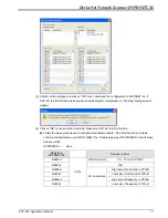
OFF
When the slave is off-line, the I/O data in
the buffer area will be cleared.
IN1 Reserved
Note:
z
Please set up the function switch when the power is switched off. After the setup is completed, re-power
DVPDNET-SL.
z
When DVPDNET-SL is operating, changing the setting of the function switch will be invalid.
z
Use slotted screwdriver to adjust the DIP switch carefully in case you scratch the switch.
2.6 Digital
Indicator
The digital indicator provides the following two functions:
DVPDNET
POWER
MS
NS
1. Displaying the node address and error messages of DVPDNET-SL and error messages.
2. Displaying the error message of slave.
2.7 Extension
Port
The extension port is used on connecting DVPDNET-SL to the left-side extension port on DVP-SV PLC MPU
or to other extension modules connected to the left side of DVP-SV.
3 Basic
Operation
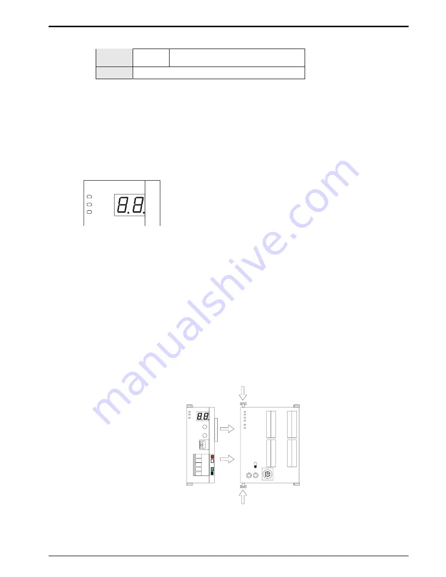
3.1
Connecting DVPDNET-SL to DVP-SV MPU
Adjust the extension clip on the left side of DVP-SV.
Meet the extension port of the MPU with DVPDNET-SL as shown in the figure below.
Fasten the extension clip.
DVPDNET
DVP28SV
RUN
STOP
3.2
Installing DVPDNET-SL and DVP-SV MPU on DIN Rail
Use 35mm DIN rail.


