


82
Processor Fan and Heat-Sink Assembly
Replacing the Processor Fan and Heat-Sink
Assembly
NOTE:
The original thermal grease can be reused if the original processor and
processor fan and heat-sink assembly are reinstalled together. If either the
processor or the processor fan and heat-sink assembly is replaced, use the thermal
pad provided in the kit to ensure that thermal conductivity is achieved.
1
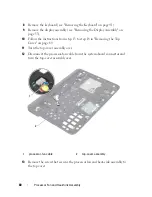
Follow the instructions in "Before You Begin" on page 9.
2
Clean the thermal grease from the bottom of the processor fan and heat-
sink assembly and reapply it.
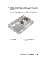
3
Route the processor-fan cable through the slot in the top cover.
4
Align the five captive screws on the processor fan and heat sink assembly
with the screw holes on the system board and tighten the screws in
sequential order (indicated on the processor heat-sink).
5
Replace the screw that secures the processor fan and heat-sink assembly to
the top-cover assembly.
6
Follow the instructions from step 9 to step 11 in "Replacing the Top
Cover" on page 72
7
Replace the display assembly (see "Replacing the Display Assembly" on
page 55).
8
Replace the keyboard (see "Replacing the Keyboard" on page 43).
9
Replace the palm-rest assembly (see "Replacing the Palm-Rest Assembly"
on page 38).
10
Follow the instructions from step 5 to step 6 in "Replacing the Optical
Drive" on page 33.
11
Replace the hard drive (see "Replacing the Hard Drive" on page 28).
12
Replace the Mini-Card(s) (see "Replacing the Mini-Card(s)" on page 24).
13
Replace the memory module(s) (see "Replacing the Memory Module(s)"
on page 17).
14
Replace the battery (see "Replacing the Battery" on page 14).
CAUTION:
Before turning on the computer, replace all screws and ensure that no
stray screws remain inside the computer. Failure to do so may result in damage to
the computer.
Summary of Contents for XPS L401X
Page 1: ...Dell XPS L401X Service Manual Regulatory model P12G series Regulatory type P12G001 ...
Page 8: ...8 Contents ...
Page 12: ...12 Before You Begin ...
Page 20: ...20 Memory Module s ...
Page 26: ...26 Wireless Mini Card s ...
Page 30: ...30 Hard Drive ...
Page 40: ...40 Palm Rest Assembly ...
Page 48: ...48 Power Button Board ...
Page 52: ...52 Coin Cell Battery ...
Page 64: ...64 Display ...
Page 68: ...68 Camera Module ...
Page 74: ...74 Top Cover ...
Page 78: ...78 Speakers ...
Page 83: ...Processor Fan and Heat Sink Assembly 83 ...
Page 84: ...84 Processor Fan and Heat Sink Assembly ...
Page 92: ...92 Daughter Board ...
Page 96: ...96 Internal Card With Bluetooth Wireless Technology ...
Page 100: ...100 AC Adapter Connector ...
Page 106: ...106 System Board ...


