


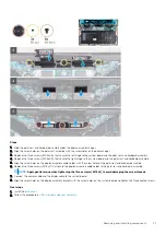


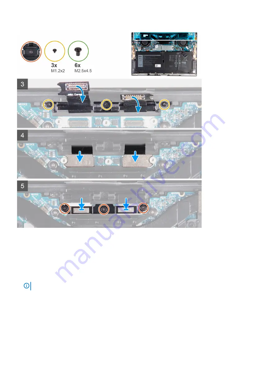
Steps
1. Slide the palm-rest and keyboard assembly under the display-assembly hinges.
2. Align the screw holes on the palm-rest assembly with the screw holes on the display hinges.
3. Replace the three screws (M2.5x4.5) that secure the left hinge to the system board and the palm-rest and keyboard assembly.
4. Replace the three screws (M2.5x4.5) that secure the right hinge to the system board and the palm-rest and keyboard assembly.
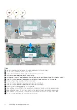
5. Align the screw holes on the display-assembly cable holder with the screw holes on the palm-rest and keyboard assembly.
6. Replace the three screws (M1.2x2) that secure the display-assembly cable holder to the palm-rest and keyboard assembly.
NOTE:
Apply gentle torque when tightening the three screws (M1.2x2) to avoid damaging the screw threads.
7. Connect the camera cable and the display cable to the system board.
8. Align the screw holes on the display-assembly bracket with the screw holes on the system board and tighten the three captive screws.
Next steps
1. Install the
.
2. Follow the procedure in
After working inside your computer
.
Removing and installing components
31
Summary of Contents for XPS 13 9300
Page 1: ...XPS 13 9300 Service Manual Regulatory Model P117G Regulatory Type P117G001 ...
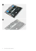
Page 12: ...12 Removing and installing components ...
Page 13: ...Removing and installing components 13 ...
Page 15: ...Removing and installing components 15 ...
Page 27: ...Removing and installing components 27 ...
Page 30: ...30 Removing and installing components ...