background image

Steps

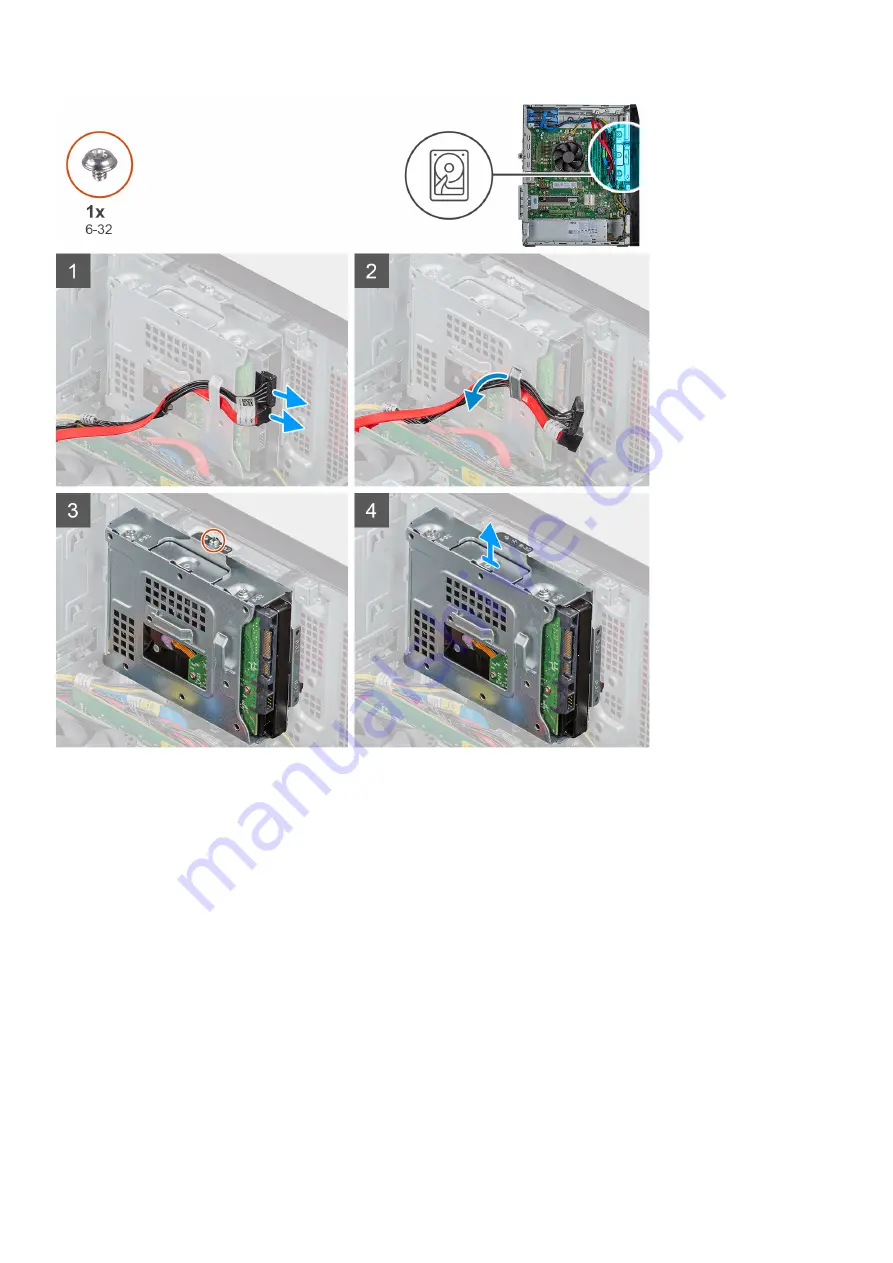
1. Lay the computer on the right side.
2. Disconnect the data and power cables from the hard drive.
3. Remove the cables from the routing guides on the hard-drive assembly.
4. Remove the single (6-32) screw that secures the 3.5-inch hard-drive assembly to the chassis.
5. Lift the hard-drive assembly away from the chassis.
6. Remove the four (6-32) screws that secure the the hard drive to the hard-drive cage.
7. Remove the hard drive from the hard-drive cage.

Installing the 3.5-inch hard drive

Prerequisites

About this task

The following images indicate the location of the 3.5-inch hard drive and provide a visual representation of the installation procedure.

26

Disassembly and reassembly

Summary of Contents for Vostro 5880

Page 1: ...Dell Vostro 5880 Service Manual Regulatory Model D28M Regulatory Type D28M004 May 2020 Rev A00 ...

Page 2: ...ential damage to hardware or loss of data and tells you how to avoid the problem WARNING A WARNING indicates a potential for property damage personal injury or death 2020 Dell Inc or its subsidiaries All rights reserved Dell EMC and other trademarks are trademarks of Dell Inc or its subsidiaries Other trademarks may be trademarks of their respective owners ...

Page 3: ... modules 16 WLAN card 17 Removing the wireless card 17 Installing the wireless card 18 Graphics card 19 Removing the graphics card 19 Installing the graphics card 20 Hard disk drive 21 Removing the 2 5 inch hard drive assembly 21 Installing the 2 5 inch hard drive assembly 23 Removing the 3 5 inch hard drive 25 Installing the 3 5 inch hard drive 26 Coin cell battery 28 Removing the coin cell batte...

Page 4: ...ions 59 Secure Boot screen options 59 Intel Software Guard Extensions screen options 59 Performance screen options 60 Power Management screen options 60 POST Behavior screen options 61 Virtualization support screen options 61 Wireless screen options 62 Advanced configuration options 62 Maintenance screen options 62 System Log screen options 62 SupportAssist System Resolution 62 Updating the BIOS i...

Page 5: ...g a wrist grounding strap or by periodically touching an unpainted metal surface at the same time as touching a connector on the back of the computer CAUTION Handle components and cards with care Do not touch the components or contacts on a card Hold a card by its edges or by its metal mounting bracket Hold a component such as a processor by its edges not by its pins CAUTION When you disconnect a ...

Page 6: ...n unpacking a static sensitive component from its shipping carton do not remove the component from the anti static packing material until you are ready to install the component Before unwrapping the anti static packaging ensure that you discharge static electricity from your body Before transporting a static sensitive component place it in an anti static container or packaging ESD field service ki...

Page 7: ...otection summary It is recommended that all field service technicians use the traditional wired ESD grounding wrist strap and protective anti static mat at all times when servicing Dell products In addition it is critical that technicians keep sensitive parts separate from all insulator parts while performing service and that they use anti static bags for transporting sensitive components Transpor...

Page 8: ...ist Table 1 Vostro 5090 Component Screw type Quantity Image Color Right side cover 6 32 2 Black 3 5 inch hard drive 6 32 1 Silver 3 5 inch hard drive cage 6 32 4 Silver WLAN card bracket M2x3 1 Black Solid state drive M2x3 1 Black Intel Optane memory module M2x3 1 Black Power supply unit 6 32 3 Silver Ports bezel 6 32 1 Silver System board 6 32 8 Black System board M2x4 1 Silver 2 8 Disassembly an...

Page 9: ...he following images indicate the location of the right side cover and provide a visual representation of the removal procedure Steps 1 Remove the two screws 6 32 that secure the right side cover to the chassis 2 Using the tab on the right side cover slide back and lift the right side cover off the chassis Disassembly and reassembly 9 ...

Page 10: ...the right side cover Prerequisites About this task The following images indicate the location of the right side cover and provide a visual representation of the installation procedure 10 Disassembly and reassembly ...

Page 11: ...e chassis Next steps 1 Follow the procedure in After working inside your computer Front bezel Removing the front cover Prerequisites 1 Follow the procedure in Before working inside your computer 2 Remove the right side cover About this task The following images indicate the location of the front cover and provide a visual representation of the removal procedure Disassembly and reassembly 11 ...

Page 12: ...ve the front cover outward from the chassis 4 Disconnect the front LED cable from the connector on the front cover Installing the front bezel Prerequisites About this task The following images indicate the location of the base cover and provide a visual representation of the installation procedure 12 Disassembly and reassembly ...

Page 13: ...l the right side cover 2 Follow the procedure in After working inside your computer Optical drive Removing the Optical drive Prerequisites 1 Follow the procedure in Before working inside your computer 2 Remove the side cover About this task The following images indicate the location of the optical drive and provides a visual representation of the removal procedure Disassembly and reassembly 13 ...

Page 14: ...4 Slide and remove the optical drive from the slot Installing the Optical drive Prerequisites If you are replacing a component remove the existing component before performing the installation procedure About this task The following images indicate the location of the Optical drive and provide a visual representation of the installation procedure 14 Disassembly and reassembly ...

Page 15: ...le through the routing guides and connect the cables to the optical drive Next steps 1 Install the side cover 2 Follow the procedure in After working inside your computer Memory modules Removing the memory modules Prerequisites 1 Follow the procedure in Before working inside your computer 2 Remove the right side cover Disassembly and reassembly 15 ...

Page 16: ... the memory module slot NOTE Repeat step 2 to step 4 to remove any other memory modules installed in your computer NOTE If the memory module is difficult to remove gently ease the memory module back and forth to remove it from the slot NOTE To prevent damage to the memory module hold the memory module by the edges Do not touch the components on the memory module Installing the memory modules Prere...

Page 17: ...it NOTE To prevent damage to the memory module hold the memory module by the edges Do not touch the components on the memory module Next steps 1 Install the right side cover 2 Follow the procedure in After working inside your computer WLAN card Removing the wireless card Prerequisites 1 Follow the procedure in Before working inside your computer 2 Remove the right side cover About this task The fo...

Page 18: ...ff the wireless card 4 Disconnect the antenna cables from the wireless card 5 Slide and remove the wireless card at an angle from the wireless card slot Installing the wireless card Prerequisites About this task The following images indicate the location of the wireless card and provide a visual representation of the installation procedure 18 Disassembly and reassembly ...

Page 19: ...d place the wireless card bracket on the wireless card 5 Replace the single M2x3 screw that secures the wireless card to the system board Next steps 1 Install the right side cover 2 Follow the procedure in After working inside your computer Graphics card Removing the graphics card Prerequisites 1 Follow the procedure in Before working inside your computer 2 Remove the side cover Disassembly and re...

Page 20: ... on the graphics card slot and lift the graphics card from the graphics card slot NOTE To remove the NVIDIA GeForce RTX 2080 graphics card lift and rotate the graphics card Installing the graphics card Prerequisites If you are replacing a component remove the existing component before performing the installation procedure About this task The following images indicate the location of the graphics c...

Page 21: ...rd 2 Using the alignment post connect the card in the connector and press down firmly Ensure that the card is firmly seated 3 Lift the pull tab to close the PCIe door Next steps 1 Install the 2 Follow the procedure in Hard disk drive Removing the 2 5 inch hard drive assembly Prerequisites 1 Follow the procedure in Before working inside your computer Disassembly and reassembly 21 ...

Page 22: ... the 2 5 inch hard drive and provide a visual representation of the removal procedure Steps 1 Disconnect the data and power cables from the hard drive 2 Press the release tabs on the hard drive carrier and slide the hard drive assembly out of the hard drive cage 22 Disassembly and reassembly ...

Page 23: ... hard drive assembly NOTE Note the orientation of the hard drive so that you can replace it correctly Installing the 2 5 inch hard drive assembly Prerequisites About this task The following images indicate the location of the 2 5 inch hard drive and provide a visual representation of the installation procedure Disassembly and reassembly 23 ...

Page 24: ...teps 1 Place the hard drive into the hard drive carrier and align the tabs on the carrier with the slots on the hard drive 2 Snap the hard drive into the hard drive carrier 24 Disassembly and reassembly ...

Page 25: ...over 2 Follow the procedure in After working inside your computer Removing the 3 5 inch hard drive Prerequisites 1 Follow the procedure in Before working inside your computer 2 Remove the right side cover About this task The following images indicate the location of the 3 5 inch hard drive and provide a visual representation of the removal procedure Disassembly and reassembly 25 ...

Page 26: ... assembly to the chassis 5 Lift the hard drive assembly away from the chassis 6 Remove the four 6 32 screws that secure the the hard drive to the hard drive cage 7 Remove the hard drive from the hard drive cage Installing the 3 5 inch hard drive Prerequisites About this task The following images indicate the location of the 3 5 inch hard drive and provide a visual representation of the installatio...

Page 27: ...n the screw hole on the hard drive assembly with the screw hole on the chassis 5 Replace the single 6 32 screw that secures the hard drive assembly to the chassis 6 Route the power cable and data cable through the routing guides on the hard drive assembly and connect the cables to the hard drive Next steps 1 Install the right side cover 2 Follow the procedure in After working inside your computer ...

Page 28: ... of the removal procedure Steps 1 Lay the computer on the right side 2 Using a plastic scribe push the coin cell battery release lever on the coin cell battery socket to release the coin cell battery out of the socket 3 Remove the coin cell battery Installing the coin cell battery Prerequisites About this task The following images indicate the location of the coin cell battery and provide a visual...

Page 29: ...er working inside your computer Solid state drive Removing the 2230 solid state drive Intel Optane memory module Prerequisites 1 Follow the procedure in Before working inside your computer 2 Remove the right side cover About this task The following images indicate the location of the solid state drive and provide a visual representation of the removal procedure Disassembly and reassembly 29 ...

Page 30: ...30 solid state drive Intel Optane memory module from the M 2 card slot on the system board Installing the 2230 solid state drive Intel Optane memory module Prerequisites About this task The following images indicate the location of the solid state drive and provide a visual representation of the installation procedure 30 Disassembly and reassembly ...

Page 31: ...t secures the 2230 solid state drive Intel Optane memory module to the system board Next steps 1 Install the right side cover 2 Follow the procedure in After working inside your computer Removing the M 2 2280 solid state drive Intel Optane memory module Prerequisites 1 Follow the procedure in Before working inside your computer 2 Remove the right side cover About this task The following images ind...

Page 32: ...d state drive Intel Optane memory from the M 2 card slot on the system board Installing the M 2 2280 solid state drive Intel Optane memory module Prerequisites About this task The following images indicate the location of the M 2 2280 solid state drive and provide a visual representation of the installation procedure 32 Disassembly and reassembly ...

Page 33: ... M2x3 screw that secures the M 2 2280 solid state drive Intel Optane memory to the system board Next steps 1 Install the right side cover 2 Follow the procedure in After working inside your computer System fan Removing the chassis fan Prerequisites 1 Follow the procedure in Before working inside your computer 2 Remove the right side cover About this task The following images indicate the location ...

Page 34: ...y pull the fan to release it from the rubber grommets 4 Remove the fan off the chassis Installing the chassis fan Prerequisites About this task The following images indicate the location of the chassis fan and provide a visual representation of the installation procedure 34 Disassembly and reassembly ...

Page 35: ... the fan snaps into position 3 Connect the fan cable to the system board Next steps 1 Install the right side cover 2 Follow the procedure in After working inside your computer Power supply unit Removing the power supply unit Prerequisites 1 Follow the procedure in Before working inside your computer 2 Remove the right side cover Disassembly and reassembly 35 ...

Page 36: ...this task The following images indicate the location of the power supply unit and provide a visual representation of the removal procedure Power supply unit with single connector 36 Disassembly and reassembly ...

Page 37: ...Power supply unit with dual connector Disassembly and reassembly 37 ...

Page 38: ...38 Disassembly and reassembly ...

Page 39: ... chassis 4 Press the securing tab on the chassis to release the power supply from its slot 5 Slide and lift the power supply unit off the chassis Installing the power supply unit Prerequisites About this task The following images indicate the location of the power supply unit and provide a visual representation of the installation procedure Installing power supply unit with single connector Disass...

Page 40: ...40 Disassembly and reassembly ...

Page 41: ...Installing power supply unit with dual connector Disassembly and reassembly 41 ...

Page 42: ...42 Disassembly and reassembly ...

Page 43: ...gh the routing guides on the chassis and connect the power cables to their respective connectors on the system board 4 Connect the power cable to the power supply unit Next steps 1 Install the right side cover 2 Follow the procedure in After working inside your computer Heatsink assembly Removing the processor fan and heat sink assembly Prerequisites 1 Follow the procedure in Before working inside...

Page 44: ...able from the system board 3 Loosen the captive screws that secure the processor fan and heat sink assembly to the system board as per the callout on the system board 4 Lift the processor fan and heat sink assembly off the system board Installing the processor fan and heat sink assembly Prerequisites About this task The following images indicate the location of the base cover and provide a visual ...

Page 45: ...cable from the system board Next steps 1 Install the right side cover 2 Follow the procedure in After working inside your computer Processor Removing the processor Prerequisites 1 Follow the procedure in Before working inside your computer 2 Remove the right side cover 3 Remove the processor fan and heat sink assembly About this task The following images indicate the location of the processor and ...

Page 46: ...en removing the processor do not touch any of the pins inside the socket or allow any objects to fall on the pins in the socket 3 Gently lift the processor from the processor socket Installing the processor Prerequisites About this task The following images indicate the location of the processor and provide a visual representation of the installation procedure 46 Disassembly and reassembly ...

Page 47: ...sor socket CAUTION Ensure that the processor cover notch is positioned underneath the alignment post 3 When the processor is fully seated in the socket pivot the release lever down and place it under the tab on the processor cover Next steps 1 Install the processor fan and heat sink assembly 2 Install the right side cover 3 Follow the procedure in After working inside your computer Disassembly and...

Page 48: ...move the wireless card 4 Remove the memory modules 5 Remove the solid state drive Intel Optane memory module 6 Remove the processor fan and heat sink assembly 7 Remove the processor About this task The following images indicate the location of the system board and provide a visual representation of the removal procedure 48 Disassembly and reassembly ...

Page 49: ...Disassembly and reassembly 49 ...

Page 50: ...50 Disassembly and reassembly ...

Page 51: ...e system board to the chassis 5 Remove the single M2x4 screw and that secures the system board to the chassis 6 Lift the system board at an angle to release the ports and remove the system board off the chassis Installing the system board Prerequisites About this task The following images indicate the location of the system board and provide a visual representation of the installation procedure Di...

Page 52: ...52 Disassembly and reassembly ...

Page 53: ...Disassembly and reassembly 53 ...

Page 54: ...sconnected from the system board 5 Align the screw holes on the ports bezel with the screw holes on the chassis 6 Replace the single 6 32 screw that secures the ports bezel to the chassis Next steps 1 Install the processor 2 Install the processor fan and heat sink assembly 3 Install the memory module 4 Install the wireless card 5 Install the solid state drive Intel Optane memory module 6 Install t...

Page 55: ...ears wait until you see the desktop Then shut down or restart your computer and try again NOTE After the Dell logo appears you can also press F12 and then select BIOS setup Navigation Keys The following table displays the system setup navigation keys NOTE For most of the system setup options changes that you make are recorded but do not take effect until you re start the system Table 2 Navigation ...

Page 56: ...LOM MAC Address Video Controller Audio Controller WiFi Device M 2PCIe SSD 0 Bluetooth Device Boot Sequence Boot Sequence Allows you to change the order in which the computer attempts to find an operating system The options are Windows Boot Manager Onboard NIC IPV4 Oboard NIC IPV6 By default all the options are checked You can also deselect any option or change the boot order UEFI Boot Path Securit...

Page 57: ...the front USB configuration Front Port 1 Bottom Right This option is enabled by default Front Port 2 Bottom Left This option is enabled by default Front Port 1 with Power Share Top Right Front Port 2 Top Left denotes a USB 3 0 capable port Rear USB Configuration This field enables or disables the rear USB configuration Rear Port 1 Bottom Right Rear Port 2 Bottom Left Rear Port 3 Top Left Rear Port...

Page 58: ...llow Non Admin Password Changes is selected UEFI Capsule Firmware Update This option controls whether the system allows the BIOS updates through UEFI capsule update packages This option is enabled by default TPM 2 0 Security Allows you to enable the Trusted Platform Module TPM during POST The options are TPM On enabled by default Clear PPI Bypass for Enabled Commands PPI Bypass for Disabled Comman...

Page 59: ...to manipulate the security key databases only if the system is in Custom Mode The Enable Custom Mode option is disabled by default The options are PK default KEK db dbx If you enable the Custom Mode the relevant options for PK KEK db and dbx appear The options are Save to File Saves the key to a user selected file Replace from File Replaces the current key with a key from a user selected file Appe...

Page 60: ...Allows you to enable or disable the additional processor sleep states C states Default setting The option is enabled Intel TurboBoost Allows you to enable or disable the Intel TurboBoost mode of the processor Enable Intel TurboBoost default Power Management screen options Option Description AC Recovery Allows you to enable or disable the computer from turning on automatically when an AC adapter is...

Page 61: ...ted when it boots Enables Keyboard Error Detection The option is enabled by default Fastboot Allows you to speed up the boot process by bypassing some of the compatibility steps The options are Minimal Thorough default Auto Extend BIOS POST Time This option created an additional pre boot delay 0 seconds default 5 seconds 10 seconds Full Screen Logo This option displays full screen logo if your ima...

Page 62: ...able SERR Messages default BIOS Downgrade This field controls flashing of the system firmware to pervious revisions Allows BIOS Downgrade Enabled by default Data Wipe This field enables user to erase data from all internal storage device BIOS Recovery Allows you to recover from certain corrupted BIOS conditions from a recover file on the user primary hard drive Enabled by default System Log screen...

Page 63: ...load method below window click Download File The File Download window appears 11 Click Save to save the file on your computer 12 Click Run to install the updated BIOS settings on your computer Follow the instructions on the screen Updating your system BIOS using a USB flash drive About this task If the system cannot load into Windows but there is still a need to update the BIOS download the BIOS f...

Page 64: ...Anyone can access the data stored on your computer if it is not locked and left unattended NOTE System and setup password feature is disabled Assigning a system setup password Prerequisites You can assign a new System or Admin Password only when the status is in Not Set About this task To enter the system setup press F2 immediately after a power on or reboot Steps 1 In the System BIOS or System Se...

Page 65: ...etup password if the Password Status is Locked About this task To enter the System Setup press F2 immediately after a power on or reboot Steps 1 In the System BIOS or System Setup screen select System Security and press Enter The System Security screen is displayed 2 In the System Security screen verify that Password Status is Unlocked 3 Select System Password alter or delete the existing system p...

Page 66: ...ery failure 3 2 PCIe or video card chip failure 3 3 Recovery Image not found 3 4 Recovery Image found but invalid 3 5 Power Rail Failure 3 6 Paid SPI volume error 3 7 Intel ME Management Engine error 4 2 CPU power cable connection issue Diagnostic error messages Table 5 Diagnostic error messages Error messages Description AUXILIARY DEVICE FAILURE The touchpad or external mouse may be faulty For an...

Page 67: ...y out the command The message is usually followed by specific information For example Printer out of paper Take the appropriate action HARD DISK DRIVE CONFIGURATION ERROR The computer cannot identify the drive type Shut down the computer remove the hard drive and boot the computer from an optical drive Then shut down the computer reinstall the hard drive and restart the computer Run the Hard Disk ...

Page 68: ...restart it Run the program again If the error message still appears see the software documentation MEMORY DOUBLE WORD LOGIC FAILURE AT ADDRESS READ VALUE EXPECTING VALUE A memory module may be faulty or improperly seated Reinstall the memory module or if necessary replace it MEMORY ODD EVEN LOGIC FAILURE AT ADDRESS READ VALUE EXPECTING VALUE A memory module may be faulty or improperly seated Reins...

Page 69: ... be malfunctioning or a memory module may be loose Run the System Memory tests and the Keyboard Controller test in Dell Diagnostics or Contact Dell X IS NOT ACCESSIBLE THE DEVICE IS NOT READY Insert a disk into the drive and try again Diagnostic error messages Table 6 Diagnostic error messages Error messages Description AUXILIARY DEVICE FAILURE The touchpad or external mouse may be faulty For an e...

Page 70: ...If the problem persists try another drive Run the Hard Disk Drive tests in Dell Diagnostics HARD DISK DRIVE FAILURE The hard drive does not respond to commands from the computer Shut down the computer remove the hard drive and boot the computer from an optical drive Then shut down the computer reinstall the hard drive and restart the computer If the problem persists try another drive Run the Hard ...

Page 71: ...t device ensure that the drive is installed properly seated and partitioned as a boot device NO BOOT SECTOR ON HARD DRIVE The operating system may be corrupted Contact Dell NO TIMER TICK INTERRUPT A chip on the system board may be malfunctioning Run the System Set tests in Dell Diagnostics NOT ENOUGH MEMORY OR RESOURCES EXIT SOME PROGRAMS AND TRY AGAIN You have too many programs open Close all win...

Page 72: ...hnical Support The computer failed to complete the boot routine three consecutive times for the same error CMOS checksum error RTC is reset BIOS Setup default has been loaded CPU fan failure CPU fan has failed System fan failure System fan has failed Hard disk drive failure Possible hard disk drive failure during POST Keyboard failure Keyboard failure or loose cable If reseating the cable does not...

Page 73: ...The following procedure provides the instructions on how to conduct a WiFi power cycle NOTE Some ISPs Internet Service Providers provide a modem router combo device Steps 1 Turn off your computer 2 Turn off the modem 3 Turn off the wireless router 4 Wait for 30 seconds 5 Turn on the wireless router 6 Turn on the modem 7 Turn on your computer Troubleshooting 73 ...

Page 74: ... and telephone based support and service options Availability varies by country and product and some services may not be available in your area To contact Dell for sales technical support or customer service issues Steps 1 Go to Dell com support 2 Select your support category 3 Verify your country or region in the Choose a Country Region drop down list at the bottom of the page 4 Select the approp...

Reviews: