background image

Memory module

Removing the memory module

Follow the procedure in 

Before working inside your computer

.

Remove the:

a

battery

b

optical drive

c

keyboard

d

base cover

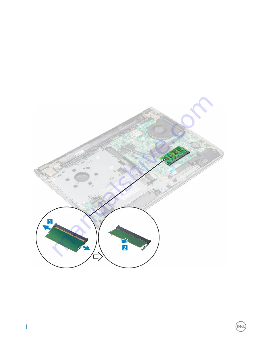
To remove memory module:

a Pull the clips securing the memory module until the memory module pops up [1].
b Remove the memory module from the system board [2].

Installing the memory module

Insert the memory module into the memory socket.

Press the memory module until the clips secure the memory module.

Install the:

20

Removing and installing components

Summary of Contents for vostro 15-3562

Page 1: ...Dell Vostro 15 3562 Owner s Manual Regulatory Model P63F Regulatory Type P63F001 ...

Page 2: ... to hardware or loss of data and tells you how to avoid the problem WARNING A WARNING indicates a potential for property damage personal injury or death Copyright 2016 Dell Inc or its subsidiaries All rights reserved Dell EMC and other trademarks are trademarks of Dell Inc or its subsidiaries Other trademarks may be trademarks of their respective owners 2016 12 Rev A00 ...

Page 3: ... 11 Installing the keyboard 13 Base cover 13 Removing the base cover 13 Installing the base cover 16 Hard drive 16 Removing the hard drive assembly 16 Removing the hard drive from the hard drive bracket 17 Installing the hard drive into the hard drive bracket 18 Installing the hard drive assembly 18 WLAN card 18 Removing the WLAN card 18 Installing the WLAN card 19 Memory module 20 Removing the me...

Page 4: ...Removing the touchpad 36 Installing the touchpad 38 System board 39 Removing the system board 39 Installing the system board 42 Input Output I O board 43 Removing the Input Output board 43 Installing the Input Output board 43 Power connector port 44 Removing the power connector 44 Installing the power connector 45 Palm rest 45 Replacing the palm rest 45 3 Technology and components 47 Processors 47...

Page 5: ... Identifying the camera in Device Manager on Windows 10 56 Starting the camera 56 Starting the camera app 56 Memory features 57 Verifying system memory 58 Verifying system memory in setup 58 Testing memory using ePSA 58 Audio drivers 58 4 System Setup 59 Boot Sequence 59 Navigation keys 59 System Setup options 60 Updating the BIOS 62 System and setup password 63 Assigning a system password and set...

Page 6: ... Handle components and cards with care Do not touch the components or contacts on a card Hold a card by its edges or by its metal mounting bracket Hold a component such as a processor by its edges not by its pins CAUTION When you disconnect a cable pull on its connector or on its pull tab not on the cable itself Some cables have connectors with locking tabs if you are disconnecting this type of ca...

Page 7: ...Ensure that the computer and all attached devices are turned off If your computer and attached devices did not automatically turn off when you shut down your operating system press and hold the power button for about 6 seconds to turn them off After working inside your computer After you complete any replacement procedure ensure that you connect external devices cards and cables before turning on ...

Page 8: ...ocedures in this document require the following tools Phillips 0 screwdriver Phillips 1 screwdriver Small plastic scribe Battery Removing the battery 1 Follow the procedure in Before working inside your computer 2 To remove the battery a Slide the release latch to release the battery 1 b Remove the battery from the computer 2 2 8 Removing and installing components ...

Page 9: ...he optical drive 1 Follow the procedure in Before working inside your computer 2 Remove the battery 3 To remove the optical drive a Remove the M2L3 screw that secures the optical drive to the computer 1 b Using a plastic scribe push the tab in the direction of the arrow indicated on the chassis 2 c Slide the optical drive out of the computer 3 Removing and installing components 9 ...

Page 10: ... inside your computer 2 Remove the a battery b optical drive 3 To remove the optical drive from the bracket a Remove the M2L2 Big head05 screw that secures the optical drive bracket b Remove the optical drive bracket from the optical drive 10 Removing and installing components ...

Page 11: ...ks into place 2 Tighten the M2L3 screw to secure the optical drive to the computer 3 Install the battery 4 Follow the procedure in After working inside your computer Keyboard Removing the keyboard 1 Follow the procedure in Before working inside your computer 2 Remove the battery 3 To remove the keyboard a Using a plastic scribe release the five tabs from the slots located above the keyboard 1 b Fl...

Page 12: ...4 To remove the keyboard cable a Disconnect the keyboard cable from the system board b Remove the keyboard from the computer 12 Removing and installing components ...

Page 13: ...place 4 Install the battery 5 Follow the procedure in After working inside your computer Base cover Removing the base cover 1 Follow the procedure in Before working inside your computer 2 Remove the a battery b optical drive c keyboard 3 To remove the base cover a Disconnect the optical drive connector and lift it to remove it from the system board 1 Removing and installing components 13 ...

Page 14: ...the M2L5 screws that secure the base cover 2 4 Flip the computer and remove the screws 8 screws M2 5L8 3 screws M2L2 2 screws M2L2 that secure the base cover to the computer 14 Removing and installing components ...

Page 15: ...5 To remove the base cover a Use a scribe to pry the edges of the base cover 1 b Lift the base cover and remove it from the computer 2 Removing and installing components 15 ...

Page 16: ...ter 4 Flip the computer over 5 Open the display and connect the optical drive connector to the system board 6 Tighten the screws to secure the base cover to the palm rest 7 Install the a keyboard b optical drive c battery 8 Follow the procedure in After working inside your computer Hard drive Removing the hard drive assembly 1 Follow the procedure in Before working inside your computer 2 Remove th...

Page 17: ...ing the hard drive from the hard drive bracket 1 Follow the procedure in Before working inside your computer 2 Remove the a battery b optical drive c keyboard d base cover e hard drive assembly 3 To remove the hard drive from the hard drive assembly a Pull the hard drive cable connector to remove it from the hard drive 1 b Remove the M3L3 screws that secure the hard drive bracket to the hard drive...

Page 18: ...e in After working inside your computer Installing the hard drive assembly 1 Insert the hard drive assembly into the slot on the computer 2 Tighten the M2L3 screws to secure the hard drive assembly to the computer 3 Connect the hard drive cable to the connector on the system board 4 Install the a base cover b keyboard c optical drive d battery 5 Follow the procedures in After working inside your c...

Page 19: ...N card from the connector on the system board 3 Installing the WLAN card 1 Install the WLAN card to the connector on the system board 2 Connect the WLAN cables to the connectors on the WLAN card 3 Place the securing tab on the WLAN card and tighten the M2L3 screw on the computer 4 Install the a base cover b keyboard c optical drive d battery 5 Follow the procedure in After working inside your comp...

Page 20: ...e cover 3 To remove memory module a Pull the clips securing the memory module until the memory module pops up 1 b Remove the memory module from the system board 2 Installing the memory module 1 Insert the memory module into the memory socket 2 Press the memory module until the clips secure the memory module 3 Install the 20 Removing and installing components ...

Page 21: ... inside your computer Coin cell battery Removing the coin cell battery 1 Follow the procedure in Before working inside your computer 2 Remove the a battery b optical drive c keyboard d base cover 3 Use a plastic scribe to lift the battery out of the slot Removing and installing components 21 ...

Page 22: ...Remove the a battery b optical drive c keyboard d base cover 3 To remove the power button board a Disconnect the system board cable from the computer 1 b Remove the display hinge screws M2 5L8 from the computer 2 3 c Flip the display hinge to reveal the power button board beneath the hinge d Remove the screw M2L2 Big head07 that secures the power button board to the chassis 4 e Peel the system boa...

Page 23: ...en the screw 5 Connect the system board cable to the power button board 6 Tighten the screws to secure it to the power button board 7 Install the a base cover b keyboard c optical drive d battery 8 Follow the procedures in After working inside your computer Heat sink Removing the heat sink 1 Follow the procedure in Before working inside your computer 2 Remove the a battery Removing and installing ...

Page 24: ...nnot be fully removed b Remove the heat sink from the system board 9 Installing the heat sink 1 Align the screws on the heat sink with the screw holders on the system board 2 Tighten the captive screws to secure it to the system board NOTE Secure the screws in the order of the callout numbers 1 2 3 4 5 6 7 8 3 Install the a base cover b keyboard c optical drive d battery 4 Follow the procedures in...

Page 25: ...m fan connector cable from the system board 1 b Remove the M2L2 screws that secure the system fan to the computer 2 c Lift and remove the system fan from the chassis 3 Installing the system fan 1 Align the system fan on the chassis 2 Secure the system fan to the computer by tightening the M2L5 screws 3 Connect the system fan connector cable to the system board connector Removing and installing com...

Page 26: ...computer Speaker Removing the speakers 1 Follow the procedure in Before working inside your computer 2 Remove the a battery b optical drive c keyboard d base cover 3 To remove the speakers a Disconnect the speaker cable from the computer 1 b Remove the speakers from the computer 2 26 Removing and installing components ...

Page 27: ...er working inside your computer Display assembly Removing the display assembly 1 Follow the procedure in Before working inside your computer 2 Remove the a battery b optical drive c keyboard d base cover e hard drive assembly f WLAN card 3 To remove the display assembly a Unroute the WLAN cable 1 b Peel white adhesive tape 2 c Lift the locking tab 3 d Disconnect the eDP cable 4 Removing and instal...

Page 28: ...4 Flip the computer 5 To remove the display assembly 28 Removing and installing components ...

Page 29: ...he display assembly 1 Align the display assembly with the chassis 2 Route the WLAN and display assembly cables through the cable securing tabs 3 Tighten the display hinges M2 5L8 screws to secure the display assembly 4 Install the a WLAN Card b hard drive assembly c base cover d keyboard e optical drive f battery 5 Follow the procedure in After working inside your computer Removing and installing ...

Page 30: ...the display bezel a Use a plastic scribe to release the tabs on the edges to release the display bezel from the display assembly b Remove the display bezel display assembly Installing the display bezel 1 Place the display bezel on the display assembly 2 Press the display bezel on the edges until it snaps onto the display assembly 3 Install the a display assembly b WLAN Card c hard drive assembly 3...

Page 31: ...low the procedure in Before working inside your computer 2 Remove the a battery b optical drive c keyboard d base cover e hard drive assembly f WLAN card g display assembly h display bezel 3 To remove the camera a Disconnect the camera cable from the camera 1 b Remove the camera from the display assembly 2 Removing and installing components 31 ...

Page 32: ...working inside your computer Display panel Removing the display panel 1 Follow the procedure in Before working inside your computer 2 Remove the a battery b optical drive c keyboard d base cover e hard drive assembly f WLAN card g display assembly h display bezel i camera 3 To remove the display panel a Remove the screws that secure the display panel to the display assembly 1 b Lift the display pa...

Page 33: ...ct the cable a Remove the tape that secures the eDP cable to the display panel 1 b Lift the locking tab and remove the eDP cable 2 c Remove the display panel from the computer 3 Removing and installing components 33 ...

Page 34: ...display panel to the display assembly 5 Install the a camera b display bezel c display assembly d WLAN Card e hard drive assembly f base cover g keyboard h optical drive i battery 6 Follow the procedure in After working inside your computer Display hinges Removing the display hinges 1 Follow the procedure in Before working inside your computer 2 Remove the a battery 34 Removing and installing comp...

Page 35: ...the display assembly 1 b Remove the display hinges 2 Installing the display hinges 1 Tighten the M2 5L2 5 screws to secure the display hinges to the display assembly 2 Install the a display panel b camera c display bezel d display assembly e WLAN Card f hard drive assembly g base cover h keyboard i optical drive j battery 3 Follow the procedure in After working inside your computer Removing and in...

Page 36: ...ive assembly f WLAN card g display assembly h display bezel i camera j display panel 3 To disconnect cable a Remove the black adhesive tape 1 b Remove the M2L3 screw that secures the LED metal shield to the touchpad 2 3 4 Remove the M2L3 screws that secure the metal bracket to the tocuhpad on the palm rest lift the bracket 1 2 36 Removing and installing components ...

Page 37: ...5 To remove touchpad a Remove the M2L2 screws that secure the touchpad to the palm rest assembly 1 b Lift the touchpad away from the palm rest assembly 2 Removing and installing components 37 ...

Page 38: ...tighten the M2L3 screws to secure it 4 Place the LED metal bracket and tighten the M2L3 screws to secure it 5 Affix the black adhesive tape 6 Install the a display panel b camera c display bezel d display assembly e WLAN Card f hard drive assembly g base cover h keyboard i optical drive j battery 7 Follow the procedure in After working inside your computer 38 Removing and installing components ...

Page 39: ...d drive assembly f WLAN card g memory module h heat sink i system fan 3 Remove the M2 5L8 screw and lift the display hinge from the chassis 1 2 4 Lift the locking tab to disconnect the following cables a hard drive connector 1 b power connector 2 c remove the adhesive tape 3 d lift the locking tab and disconnect the eDP connector 4 Removing and installing components 39 ...

Page 40: ...e speaker 5 f touchpad connector 6 g I O connector 7 5 Remove the M2L3 screw that secures the system board to the computer 1 and lift the system board 2 40 Removing and installing components ...

Page 41: ...he system board 7 To remove the system board a Peel the white adhesive tape 1 b Unlock the tab and disconnect the power cable 2 c Remove the system board from the computer Removing and installing components 41 ...

Page 42: ... system board to the computer 6 Tighten the display hinge screw to the computer 7 Connect the following cables to the system board a hard drive connector b touchpad connector c speaker connector d I O connector e eDP connector f power connector 8 Install the a system fan b heat sink c memory module d WLAN Card e hard drive assembly f base cover g keyboard h optical drive i battery 42 Removing and ...

Page 43: ...battery b optical drive c keyboard d base cover e hard drive assembly 3 To remove the Input Output board I O board a Disconnect the I O board cable 1 b Remove the M2L3 screw and lift I O board from the computer 2 3 Installing the Input Output board 1 Place the I O board on the computer 2 Connect the input output I O board cable and tighten the M2L3 screw Removing and installing components 43 ...

Page 44: ...procedure in Before working inside your computer 2 Remove the a battery b optical drive c keyboard d base cover e hard drive assembly f WLAN card g memory module h heat sink i system fan j coin cell battery k system board 3 To remove the power connector a Unroute the cable 1 b Remove the screw that secures the power connector to the computer 2 c Lift the power connector 3 44 Removing and installin...

Page 45: ... base cover i keyboard j optical drive k battery 5 Follow the procedure in After working inside your computer Palm rest Replacing the palm rest 1 Follow the procedure in Before working inside your computer 2 Remove the a battery b optical drive c keyboard d base cover e hard drive assembly f WLAN card g memory module h heat sink i system fan j system board k display assembly NOTE After the removal...

Page 46: ...a display assembly b system board c system fan d heat sink e memory module f WLAN Card g hard drive assembly h base cover i keyboard j optical drive k battery 4 Follow the procedure in After working inside your computer 46 Removing and installing components ...

Page 47: ...ssors in Windows 10 1 Tap Search the Web and Windows 2 Type Device Manager 3 Tap Processor The basic information of the processor is displayed Verifying the processor usage in Task Manager 1 Press and hold the taskbar 2 Select Start Task Manager The Windows Task Manager window is displayed 3 Click the Performance tab in the Windows Task Manager window The processor performance details are displaye...

Page 48: ...op 2 Go to Dell com support 3 Click Product Support enter the Service Tag of your laptop and then click Submit NOTE If you do not have the Service Tag use the autodetect feature or manually browse for your laptop model 4 Click Drivers and Downloads 5 Select the operating system installed in your laptop 6 Scroll down the page expand Chipset and select your chipset driver 7 Click Download File to do...

Page 49: ...r the chipset Intel chipset drivers Verify if the Intel chipset drivers are already installed in the laptop Table 1 Intel chipset drivers Before installation After installation Intel HD Graphics This laptop is shipped with the Intel HD Graphics graphics chipset Intel HD Graphics drivers Verify if the Intel HD Graphics drivers are already installed in the laptop Technology and components 49 ...

Page 50: ...ager in the search box and tap Device Manager from the left pane 3 Expand Display adapters The display adapters are displayed Rotating the display 1 Press and hold on the desktop screen A sub menu is displayed 2 Select Graphic Options Rotation and choose on of the following Rotate to Normal Rotate to 90 Degrees Rotate to 180 Degrees Rotate to 270 Degrees 50 Technology and components ...

Page 51: ...nstall 7 Click Download File to download the graphic driver for your laptop 8 After the download is complete navigate to the folder where you saved the graphic driver file 9 Double click the graphic driver file icon and follow the instructions on the screen Changing the screen resolution 1 Press and hold the desktop screen and select Display Settings 2 Tap or click Advanced display settings 3 Sele...

Page 52: ...en 5 Remove all excess moisture as it may damage your screen 6 Let the display dry thoroughly before you turn it on 7 For stains that are hard to remove repeat this procedure till the display is clean Connecting to external display devices Follow these steps to connect your laptop to an external display device 1 Ensure that the projector is turned on and plug the projector cable into a video port ...

Page 53: ... Down button to enter BIOS setup To enter the Boot selection menu press the Volume Up button Hard drive is listed under the System Information under the General group USB features The Universal Serial Bus or well known as USB was introduced to the PC world in 1996 which dramatically simplified the connection between host computer and peripheral devices such as mice and keyboards external hard driv...

Page 54: ...ctors and cable The topics below cover some of the most commonly asked questions regarding USB 3 0 Speed Currently there are 3 speed modes defined by the latest USB 3 0 specification They are Super Speed Hi Speed and Full Speed The new SuperSpeed mode has a transfer rate of 4 8Gbps While the specification retains Hi Speed and Full Speed USB mode commonly known as USB 2 0 and 1 1 respectively the s...

Page 55: ... 8Gbps speed the standard will find its way into some products that previously weren t USB territory like external RAID storage systems Listed below are some of the available SuperSpeed USB 3 0 products External Desktop USB 3 0 Hard Drives Portable USB 3 0 Hard Drives USB 3 0 Drive Docks Adapters USB 3 0 Flash Drives Readers USB 3 0 Solid state Drives USB 3 0 RAIDs Optical Media Drives Multimedia ...

Page 56: ...kelihood of this happening is remote Camera features This laptop comes with front facing camera with the image resolution of 1280 x 720 maximum Identifying the camera in Device Manager on Windows 10 1 In the Search box type device manager and tap to start it 2 Under Device Manager expand Imaging devices Starting the camera To start the camera open an application that uses the camera For instance i...

Page 57: ... 3 If the Camera App is not available in the apps list search for it Memory features In this laptop the memory RAM is a part of the system board This laptop supports 4 32 GB DDR4 SDRAM memory up to 2133 MHz Technology and components 57 ...

Page 58: ...ion The memory information is displayed on the right pane Testing memory using ePSA 1 Turn on or restart your laptop 2 Perform one of the following actions after the Dell logo is displayed With keyboard Press F2 Without keyboard Press and hold the Volume Up button when the Dell logo is displayed on the screen When the F12 boot selection menu is displayed select Diagnostics from the boot menu and p...

Page 59: ...r hard drive During the Power on Self Test POST when the Dell logo appears you can Access System Setup by pressing F2 key Bring up the one time boot menu by pressing F12 key The one time boot menu displays the devices that you can boot from including the diagnostic option The boot menu options are Removable Drive if available STXXXX Drive NOTE XXX denotes the SATA drive number Optical Drive Diagno...

Page 60: ...tag of your computer if available CPU Type Displays the type of processor CPU Speed Displays the speed of the processor CPU ID Displays the processor ID CPU Cache L1 Cache Displays the processor L1 cache size L2 Cache Displays the processor L2 cache size First HDD Displays the model number and capacity of the hard drive mSATA Device Displays the model number and capacity of the optical drive Syste...

Page 61: ...e or disable the Optical Device Default Enabled Boot Disable You can enable or disable the Boot Disable Default Disabled USB debug You can enable or disable the USB debug Default Disabled Auto OS Recovery Threshold Allows you to control the automatic boot flow for SupportAssist System Options are Off 1 2 enabled by default 3 SupportAssist OS Recovery Allows you to recover the SupportAssist OS Reco...

Page 62: ...rged and connected to a power outlet 1 Restart the computer 2 Go to Dell com support 3 Enter the Service Tag or Express Service Code and click Submit NOTE To locate the Service Tag click Where is my Service Tag NOTE If you cannot find your Service Tag click Detect My Product Proceed with the instructions on screen 4 If you are unable to locate or find the Service Tag click the Product Category of ...

Page 63: ... system password A password can have up to 32 characters The password can contain the numbers 0 through 9 Only lower case letters are valid upper case letters are not allowed Only the following special characters are allowed space 3 Type the system password that you entered earlier in the Confirm new password field and click OK 4 Press Esc and a message prompts you to save the changes 5 Press Y to...

Page 64: ...5 Press Esc and a message prompts you to save the changes 6 Press Y to save the changes and exit from System Setup The computer reboots 64 System Setup ...

Page 65: ...o test only your computer Using this program with other computers may cause invalid results or error messages NOTE Some tests for specific devices require user interaction Always ensure that you are present at the computer terminal when the diagnostic tests are performed Running the ePSA diagnostics 1 Power on the computer 2 As the computer boots press the F12 key as the Dell logo appears 3 On the...

Page 66: ...eron Processors Apollo Lake L2 cache 2 MB Table 11 Memory specifications Feature Specification Memory connector One internally accessible DDR3L connectors Memory capacity 4 GB and 8 GB Memory speed 1600 Mhz Minimum memory 4 GB Maximum memory 8 GB Table 12 Audio specifications Feature Specification Type Two channel high definition audio Controller Realtek ALC3246 with Waves MaxxAudio Stereo convers...

Page 67: ...pecification Network adapter 10 100 1000 Mbps Ethernet LAN on Motherboard LOM Wireless Wi Fi 802 11 b g n Bluetooth 4 0 Table 16 Ports and connectors specifications Feature Specification Audio One headphone microphone combo port headset Video VGA and HDMI out Network adapter One RJ 45 port USB Two USB 3 0 ports One USB 2 0 port NOTE The powered USB 3 0 connector also supports Microsoft Kernel Debu...

Page 68: ...fications Feature Specification Number of keys US 101 Brazil 104 UK 102 and Japan 105 Table 19 Touchpad specifications Feature Specification Active Area X axis 105 00 mm 4 13 inches Y axis 80 00 mm 3 14 inches Table 20 Battery specifications Feature Specification Type 4 cell smart lithium ion 47 WHr Dimensions Height 20 00 mm 0 78 inch Width 270 00 mm 10 63 inches Depth 37 50 mm 1 47 inches Weight...

Page 69: ...F Table 22 Physical Feature Specification Height 23 65 mm 0 93 inches Width 380 00 mm 14 96 inches Depth 260 30 mm 10 24 inches Weight 2 29 kg 5 04 lb Table 23 Environmental specifications Feature Specification Temperature Operating 0 C to 35 C 32 F to 95 F Storage 40 C to 65 C 40 F to 149 F Relative humidity maximum Operating 10 to 90 non condensing Storage 0 to 95 non condensing Altitude maximum...

Page 70: ...70 Technical specifications ...

Page 71: ... service options Availability varies by country and product and some services may not be available in your area To contact Dell for sales technical support or customer service issues 1 Go to Dell com support 2 Select your support category 3 Verify your country or region in the Choose a Country Region drop down list at the bottom of the page 4 Select the appropriate service or support link based on...

Reviews: