Dell UP2720QB, Teardown Manual
The Dell UP2720QB Teardown Manual is an essential resource for tech enthusiasts and DIY enthusiasts alike. Easily download the comprehensive manual, free of charge, from our website manualshive.com, and unlock step-by-step instructions to dismantle and explore the inner workings of this exceptional product.
Share
Download


Reviews:
No comments
Related manuals for UP2720QB
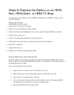
HRM-Run
Brand: Garmin Pages: 3

WGNBPW-720
Brand: Walgreens Pages: 41

BM600
Brand: CALMPER Pages: 18

G 150
Brand: Rossmax Pages: 53

ZL 7261 CL-5
Brand: Vision Pages: 3

G03-1951WQS-F
Brand: JETWAY Pages: 10

AW2720HFA
Brand: Alienware Pages: 67

JC199
Brand: Hanns.G Pages: 20

RS+ Series
Brand: NewLine Pages: 86

IPC-DT
Brand: Contec Pages: 52

TD2420-2-CN
Brand: ViewSonic Pages: 26

MV191SN
Brand: MegaVision Pages: 18

VA2016W - 20" LCD Monitor
Brand: ViewSonic Pages: 23

MOTORSAVER 455-480R
Brand: SymCom Pages: 4

LEM-150
Brand: TV Logic Pages: 52

SG210
Brand: Balmar Pages: 19

VE702m
Brand: ViewSonic Pages: 16

HP248UJB
Brand: HANNspree Pages: 22


