background image


About your monitor

       |


27

Handling and moving your display

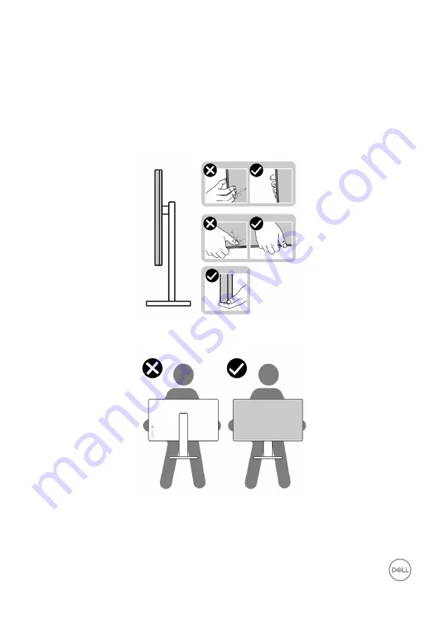
To ensure the monitor is handled safely when lifting or moving it, follow the guidelines 
mentioned below:

•  Before moving or lifting the monitor, turn off your computer and the monitor.
•  Disconnect all cables from the monitor.
•  Place the monitor in the original box with the original packing materials.
•  Hold the bottom edge and the side of the monitor firmly without applying 

excessive pressure when lifting or moving the monitor.

•  When lifting or moving the monitor, ensure the screen is facing away from you 

and do not press on the display area to avoid any scratches or damage.

•  When transporting the monitor, avoid any sudden shock or vibration to it.

Summary of Contents for U2421E

Page 1: ...Model U2421E Regulatory model U2421Et Dell UltraSharp 24 USB C Hub Monitor U2421E User s Guide ...

Page 2: ...r loss of data if instructions are not followed WARNING A WARNING indicates a potential for property damage personal injury or death Copyright 2020 Dell Inc or its subsidiaries All rights reserved Dell EMC and other trademarks are trademarks of Dell Inc or its subsidiaries Other trademarks may be trademarks of their respective owners 2020 10 Rev A00 ...

Page 3: ...ti Stream Transport MST Modes 13 USB C MST Multi Stream Transport MST Modes 13 Electrical specifications 14 Physical characteristics 15 Environmental characteristics 16 Pin assignments 17 Plug and Play 24 LCD monitor quality and pixel policy 24 Ergonomics 25 Handling and moving your display 27 Maintenance guidelines 28 Cleaning your monitor 28 Setting up the monitor 29 Connecting the stand 29 Usin...

Page 4: ...41 Using the joystick control 41 Using the rear panel controls 42 Using the OSD lock function 43 Front panel button 46 Using the On Screen Display OSD Menu 47 Accessing the menu system 47 OSD warning messages 57 Setting the maximum resolution 61 Troubleshooting 62 Self test 62 Built in diagnostics 63 Common Problems 64 Product specific problems 65 Universal Serial Bus USB specific problems 68 Appe...

Page 5: ...ed to operate with the AC power available in your location Keep the monitor in room temperature Excessive cold or hot conditions can have an adverse effect on the liquid crystal of the display Do not subject the monitor to severe vibration or high impact conditions For example do not place the monitor inside a car trunk Unplug the monitor when it is going to be left unused for an extended period o...

Page 6: ...component is missing contact Dell For more information see Contact Dell NOTE Some components may be optional and may not ship with your monitor Some features may not be available in certain countries Display Stand riser Stand base Power cable varies by country DisplayPort cable DisplayPort to DisplayPort USB Type C cable C to A ...

Page 7: ...rystal Display LCD and LED backlight The monitor features include 61 13 cm 24 1 in active area display Measured diagonally 1920 x 1200 16 10 resolution plus full screen support for lower resolutions Wide viewing angles with 99 sRGB color with an average Delta E 2 Tilt swivel pivot and vertical extension adjustment capabilities Removable pedestal stand and Video Electronics Standards Association VE...

Page 8: ...entifying parts and controls Front view 1 Label Description Use 1 Power LED indicator Solid white light indicates the monitor is turned on and functioning normally Blinking white light indicates the monitor is in Standby Mode ...

Page 9: ... On Off button To turn the monitor on or off 5 Joystick Use it to control the OSD menu For more information see Operating the Monitor 6 Mac address Barcode serial number and Service Tag label Refer to this label if you need to contact Dell for technical support The Service Tag is a unique alphanumeric identifier that enables Dell service technicians to identify the hardware components in your comp...

Page 10: ...A 9 V 3 A 5 V 3 A NOTE USB Type C is not supported on Windows versions that are prior to Windows 10 6 DP port out DP output for MST multi stream transport capable monitor To enable MST refer to instruction on section Connecting the Monitor for DP MST Function NOTE Remove the rubber plug when using DP out connector 7 9 11 SuperSpeed USB 5 Gbps USB 3 2 Gen1 3 Connect your USB device You can use thes...

Page 11: ...using a M3 x 8 mm screw screw not included Monitor specifications Screen type Active matrix TFT LCD Panel Type In plane switching Technology Aspect ratio 16 10 Viewable image dimensions Diagonal 61 13 cm 24 1 in Active Area Horizontal 518 4 mm 20 40 in Vertical 324 0 mm 12 76 in Area 167961 6 mm2 260 30 in 2 Pixel pitch 0 27 mm x 0 27 mm Pixel per inch PPI 93 95 Viewing angle Horizontal 178 typica...

Page 12: ... 3 2 Gen 1 with BC 1 2 charging capability at 2 A max 1 x Analog 2 0 audio line out 3 5 mm jack 1 x RJ45 Border width edge of monitor to active area Top Left Right Bottom 6 2 mm 6 2 mm 9 1 mm Adjustability Height adjustable stand 150 mm Tilt 5 to 21 Swivel 45 to 45 Pivot 90 to 90 Cable management Yes Dell Display Manager DDM Compatibility Easy Arrange and other key features Security Security lock ...

Page 13: ... 46 88 75 49 5 VESA 1024 x 768 48 36 60 65 VESA 1024 x 768 60 02 75 78 75 MAC 1152 x 864 67 5 75 108 VESA 1280 x 1024 64 60 108 VESA 1280 x 1024 80 75 135 CVT 1600 x 900 55 99 60 118 25 CVT 1920 x 1080 67 5 60 148 5 CVT 1920 x 1200 74 04 60 154 DP MST Multi Stream Transport MST Modes MST Source Monitor Maximum number of external monitors that can be supported 1920 x 1200 60 Hz 1920 x 1200 60 Hz 2 ...

Page 14: ...On Mode as defined in Energy Star 8 0 version TEC Total energy consumption in kWh as defined in Energy star 8 0 version This document is informational only and reflects laboratory performance Your prod uct may perform differently depending on the software components and peripherals you ordered and shall have no obligation to update such information Accordingly the customer should not rely upon thi...

Page 15: ...o DP 1 8 M cable USB Type C C to C 1 0 M cable USB Type C C to A 1 8 M cable Dimensions with stand Height extended 510 7 mm 20 11 in Height compressed 364 0 mm 14 33 in Width 530 8 mm 20 90 in Depth 173 0 mm 6 81 in Dimensions without stand Height 339 3 mm 13 36 in Width 530 8 mm 20 90 in Depth 50 0 mm 1 97 in Stand dimensions Height extended 410 8 mm 16 17 in Height compressed 364 0 mm 14 33 in W...

Page 16: ... registration status by country TCO Certified Display RoHS Compliant BFR PVC Free monitor excluding external cables Meets NFPA 99 leakage current requirements Arsenic Free glass and Mercury Free for the panel only Temperature Operating 0 C to 40 C 32 F to 104 F Non operating 20 C to 60 C 4 F to 140 F Humidity Operating 10 to 80 non condensing Non operating 5 to 90 non condensing Altitude Operating...

Page 17: ...port in Pin number 20 pin side of the connected signal cable 1 ML3 n 2 GND 3 ML3 p 4 ML2 n 5 GND 6 ML2 p 7 ML1 n 8 GND 9 ML1 p 10 ML0 n 11 GND 12 ML0 p 13 CONFIG1 14 CONFIG2 15 AUX CH p 16 GND 17 AUX CH n 18 Hot Plug Detect 19 Return 20 DP_PWR ...

Page 18: ...Pin number 20 pin side of the connected signal cable 1 ML0 p 2 GND 3 ML0 n 4 ML1 p 5 GND 6 ML1 n 7 ML2 p 8 GND 9 ML2 n 10 ML3 p 11 GND 12 ML3 n 13 CONFIG1 14 CONFIG2 15 AUX CH p 16 GND 17 AUX CH n 18 Hot Plug Detect 19 Return 20 DP_PWR ...

Page 19: ...2 2 TMDS DATA 2 SHIELD 3 TMDS DATA 2 4 TMDS DATA 1 5 TMDS DATA 1 SHIELD 6 TMDS DATA 1 7 TMDS DATA 0 8 TMDS DATA 0 SHIELD 9 TMDS DATA 0 10 TMDS CLOCK 11 TMDS CLOCK SHIELD 12 TMDS CLOCK 13 CEC 14 Reserved N C on device 15 DDC CLOCK SCL 16 DDC DATA SDA 17 DDC CEC Ground 18 5 V POWER 19 HOT PLUG DETECT ...

Page 20: ...C port Pin Signal Pin Signal A1 GND B12 GND A2 SSTXp1 B11 SSRXp1 A3 SSTXn1 B10 SSRXn1 A4 VBUS B9 VBUS A5 CC1 B8 SBU2 A6 Dp1 B7 Dn1 A7 Dn1 B6 Dp1 A8 SBU1 B5 CC2 A9 VBUS B4 VBUS A10 SSRXn2 B3 SSTXn2 A11 SSRXp2 B2 SSTXp2 A12 GND B1 GND ...

Page 21: ...con supports fast current charging capability if the device is 5V 3A compatible NOTE The monitor s USB ports work only when the monitor is on or in the power save mode In power save mode if the USB cable Type C to Type C is plugged in the USB ports can work normally Otherwise follow the OSD setting of USB if the setting is On During Standby then USB work normally otherwise USB is disabled If you t...

Page 22: ...tion Install the Realtek USB GBE Ethernet Controller Driver available for your system This is available for download at www dell com support under the Driver and download section Network RJ45 data rate via USB C max speed is 1000 Mbps NOTE This LAN port is 1000Base T IEEE 802 3az compliant supporting Mac Address Printed on model label Pass thru Wake on LAN WOL from standby mode S3 only and PXE Boo...

Page 23: ...scription Right LED Amber or Green Speed indicator Amber On 1000 Mbps Green On 100 Mbps Off 10 Mbps Left LED Green Link Activity indicator Blinking Activity on the port Green On Link is being established Off Link is not established NOTE RJ45 cable is non in box standard accessory ...

Page 24: ...ettings Most monitor installations are automatic you can select different settings if desired For more information about changing the monitor settings see Operating the Monitor LCD monitor quality and pixel policy During the LCD monitor manufacturing process it is not uncommon for one or more pixels to become fixed in an unchanging state which are hard to see and do not affect the display quality ...

Page 25: ...m your monitor and gaze at a distant object at 20 feet away for at least 20 seconds during the breaks 5 Perform stretches to relieve tension in the neck arm back and shoulders during the breaks Make sure that the monitor screen is at eye level or slightly lower when you are sitting in front of the monitor Adjust the tilt of the monitor its contrast and brightness settings Adjust the ambient lighti...

Page 26: ...and or get up and walk around at regular intervals Keep the area under your desk clear of obstructions and cables or power cords that may interfere with comfortable seating or present a potential trip hazard monitor screen at or below eye level monitor and keyboard positioned directly in front of the user feet flat on the floor wrists relaxed and flat ...

Page 27: ...all cables from the monitor Place the monitor in the original box with the original packing materials Hold the bottom edge and the side of the monitor firmly without applying excessive pressure when lifting or moving the monitor When lifting or moving the monitor ensure the screen is facing away from you and do not press on the display area to avoid any scratches or damage When transporting the mo...

Page 28: ...o clean your anti static screen lightly dampen a soft clean cloth with water If possible use a special screen cleaning tissue or solution suitable for the anti static coating Do not use benzene thinner ammonia abrasive cleaners or compressed air Use a lightly dampened soft cloth to clean the monitor Avoid using detergent of any kind as some detergents leave a milky film on the monitor If you notic...

Page 29: ...le only for the stand that was shipped with your monitor If you are connecting a stand that you purchased from any other source follow the set up instructions that were included with the stand To attach the monitor stand 1 Align and place the stand riser on the stand base 2 Open the screw handle at the bottom of the stand base and turn it clockwise to secure the stand assembly 3 Close the screw ha...

Page 30: ... monitor 4 Open the protective cover on the monitor to access the VESA slot on the monitor 5 Slide the tabs on the stand riser into the slots on the display back cover and lower the stand assembly to snap it into place ...

Page 31: ... 31 6 Hold the stand riser and lift the monitor carefully then place it on a flat surface NOTE Hold the stand riser firmly when lifting the monitor to avoid any accidental damage 7 Lift the protective cover from the monitor ...

Page 32: ...ere included with the stand Tilt swivel and vertical extension With the stand attached to the monitor you can tilt the monitor for the most comfortable viewing angle 5 45 45 150 mm 21 NOTE The stand is detached when the monitor is shipped from the factory Rotating the Display Before you rotate the display extend the display vertically until the top of the stand riser and then tilt the display back...

Page 33: ...r with a non Dell computer go to the graphics card manufacturer s website or your computer manufacturer website for information on how to rotate the contents of your display To configure the Display Settings 1 Right click on the Desktop and click Properties 2 Select the Settings tab and click Advanced 3 If you have an AMD graphics card select the Rotation tab and set the preferred rotation 4 If yo...

Page 34: ...able and the USB Type C cable from your monitor to the computer 3 Turn on your monitor 4 Select the correct input source from the OSD Menu on your monitor and then turn on your computer NOTE U2421E default setting is DisplayPort 1 4 A DisplayPort 1 1 Graphic card may not display normally Please refer to product specific problems No image when using DP connection to the PC to change default setting...

Page 35: ...ing the monitor for DP Multi Stream Transport MST function DP DP out DP DP NOTE Supports the DP MST feature To make use of this feature your PC Graphics Card must be certified to at least DP1 2 with MST option NOTE Remove the rubber plug when using DP out connector ...

Page 36: ...Supports USB Power Delivery PD with profiles up to 90 W NOTE Regardless of the power requirement actual power consumption of your laptop or the remaining power runtime in your battery the Dell U2421E monitor is designed to supply power delivery of up to 90 W to your laptop Rated power on laptops that have USB Type C with PowerDelivery Maximum charging power 45 W 45 W 65 W 65 W 90 W 90 W 130 W Not ...

Page 37: ... USB Type C NOTE The maximum number of supported U2421E via MST is subjected to the bandwith of the USB C source Please refer to product specific problems No image when using USB Type C MST NOTE Remove the rubber plug when using DP out connector Connecting the monitor for RJ45 Cable Optional USB Type C USB Type C RJ45 ...

Page 38: ...g your monitor using Kensington lock optional The security lock slot is located at the bottom of the monitor See Security lock slot For more information on using the Kensington lock purchased separately see the documentation that is shipped with the lock Secure your monitor to a table using the Kensington security lock NOTE The image is for the purpose of illustration only Appearance of the lock m...

Page 39: ...he following instructions are applicable only for the stand that was shipped with your monitor If you are connecting a stand that you purchased from any other source follow the set up instructions that were included with the stand To remove the stand 1 Place the monitor on a soft cloth or cushion 2 Press and hold the stand release button 3 Lift the stand up and away from the monitor 2 3 ...

Page 40: ...cushion on a stable flat table 2 Remove the stand 3 Use a Phillips crosshead screwdriver to remove the four screws securing the plastic cover 4 Attach the mounting bracket from the wall mounting kit to the monitor 5 Mount the monitor on the wall as instructed in the documentation that shipped with the wall mounting kit NOTE For use only with UL or CSA or GS listed wall mount bracket with minimum w...

Page 41: ...o confirm the settings and exit Joystick Description When the OSD menu is on press the button to confirm the selection or save the settings When the OSD menu is off press the button to launch the OSD main menu See Accessing the menu system For 2 way right and left directional navigation Move right to enter the submenu Move left to exit from the submenu Increases right or decreases left the paramet...

Page 42: ...is Menu button to launch the on screen display OSD and select the OSD menu See Accessing the menu system 2 Display Info Use this button to choose from a list of Display Info 3 Input Source Use this button to choose from a list of Input Source 4 Preset Modes Use this button to choose from a list of preset color modes 5 Brightness Contrast To directly access the Brightness Contrast adjustment slider...

Page 43: ...anel control buttons to prevent access to the OSD menu and or power button Use the Lock menu to lock the button s 1 Select one of the following options 2 The following message appears 3 Select Yes to lock buttons Once locked pressing any control button will display the lock icon ...

Page 44: ...Description 1 Menu Button lock Select this option to lock OSD menu function 2 Power Button lock Use this option to lock power button This will prevent the user to turn off the monitor using the power button 3 Menu and Power Button lock Use this option to lock OSD menu and power button to turn off the monitor 4 Built in Diagnostics Use this option to run the built in diagnostics see Built in Diagno...

Page 45: ...following table describes the options to unlock the front panel control buttons Options Description 1 Menu Button unlock Use this option to unlock OSD menu function 2 Power Button unlock Use this option to unlock power button to turn off the monitor 3 Menu and Power Button unlock Use this option to unlock OSD menu and power button to turn off the monitor ...

Page 46: ...e image settings Front Panel Description 1 Up Down Use the Up increase and Down decrease buttons to adjust items in the OSD menu 2 Previous Use the Previous button to go back to the previous menu 3 Next Use the Next button to confirm your selection 4 Tick Use the Tick button to confirm your selection ...

Page 47: ...of the backlight minimum 0 maximum 100 Move the joystick up to increase brightness Move the joystick down to decrease brightness Contrast Adjust the Brightness first and then adjust Contrast only if further adjustment is necessary Move the joystick up to increase contrast and Move the joystick down to decrease contrast between 0 and 100 The Contrast function adjusts the degree of difference betwee...

Page 48: ...joystick button to confirm the selection Auto Select Turn on the function to allow the monitor to automatically scan for available input sources Press the joystick button to confirm the selection Auto Select for USB C Allows you to set Auto Select for USB Type C to Prompt for Multiple Inputs always show Switch to USB Type C Video Input message for user to choose whether to switch or not Yes The mo...

Page 49: ...certified by TUV to reduce blue light output and create a more relaxing and less stimulating image while reading content on the screen Movie Ideal for movies Game Ideal for most gaming applications Color Temp The screen appears warmer with a red yellow tint with slider set at 5 000K or cooler with blue tint with slider set at 10 000K Custom Color Allows you to manually adjust the color settings Pr...

Page 50: ... DP HDMI cable YPbPr Select this option if your DVD player supports only YPbPr output Hue Use joystick up or down to adjust the hue from 0 to 100 NOTE Hue adjustment is available only for Movie and Game mode Saturation Use joystick up or down to adjust the saturation from 0 to 100 NOTE Saturation adjustment is available only for Movie and Game mode Reset Color Resets your monitor s color settings ...

Page 51: ...the sharpness from 0 to 100 Response Time Allows you to set the Response Time to Normal or Fast MST DP Multi Stream Transport Set to ON enables MST DP out Set to OFF disables MST function NOTE When DP USB Type C upstream cable and DP downstream cable is connected monitor will set MST ON automatically this action will only be done once after Factory Reset or Display Reset Reset Display Resets all s...

Page 52: ...anish French German Brazilian Portuguese Russian Simplified Chinese or Japanese Rotation Rotates the OSD by 0 90 180 270 degrees You can adjust the menu according to your display rotation Transparency Select this option to change the menu transparency by moving the joystick up or down min 0 max 100 Timer OSD Hold Time Sets the length of time the OSD remains active after you press a button Move the...

Page 53: ...o prevents accidental activation in multiple monitors side by side setup Menu Buttons Through OSD to lock the Menu buttons Power Button Through OSD to lock the Power button Menu Power Buttons Through OSD to lock the all of Menu and Power buttons Disable Move the Joystick left and hold for 4 sec Reset Menu Resets all settings under the Reset menu to the factory defaults ...

Page 54: ...hortcut key 4 Shortcut key 5 Power Button LED Allows you to set the state of the power light to save energy USB C Charging 90 W Allows you to enable or disable USB C Charging 90 W charging function during monitor power off mode Other USB Charging Allows you to enable or disable Other USB Charging function during monitor Standby mode Reset Persona lization Resets all settings under the Personalize ...

Page 55: ...o on Display Info Displays the monitor s current settings DDC CI DDC CI Display Data Channel Command Interface allows your monitor parameters brightness color balance and etc to be adjustable via the software on your computer You can disable this feature by selecting Off Enable this feature for best user experience and optimum performance of your monitor ...

Page 56: ... Displays the firmware version of your monitor Service Tag Displays the Service Tag The Service Tag is a unique alphanumeric identifier that allows Dell to identify the product specifications and access warranty information NOTE The Service Tag is also printed on a label located at the back of the cover Reset Others Resets all settings under the Others menu to the factory defaults Factory Reset Re...

Page 57: ...ecifications for the Horizontal and Vertical frequency ranges addressable by this monitor Recommended mode is 1920 x 1200 You can see the following message before the DDC CI function is disabled When the monitor enters the Standby mode the following message will appear Activate the computer and wake up the monitor to gain access to the OSD If you press any button other than the power button the fo...

Page 58: ...nitor under the following conditions When Auto Select for USB C is set to Prompt for Multiple Inputs When the USB C cable is connected to the monitor Select OSD items of Factory Reset in Other feature the following message will appear When you select Yes to reset to default settings the following message will appear ...

Page 59: ...f adjust the Brightness level above the default level over 75 the following message will appear When user selects Yes the power message is displayed only once When user select No the power warning message will pop up again The power warning message will appear again only when the user does a Factory Reset from the OSD menu ...

Page 60: ...Operating the monitor If either USB Type C DP HDMI input is selected and the corresponding cable is not connected a floating dialog box as shown below appears or or See Troubleshooting for more information ...

Page 61: ...Display Settings 2 Click Advanced display settings 3 Click the dropdown list of Resolution and select 1920 x 1200 4 Click Apply If you do not see 1920 x 1200 as an option you may need to update your graphics driver Depending on your computer complete one of the following procedures If you have a Dell desktop or portable computer Go to http www dell com support enter your service tag and download t...

Page 62: ...mputer and the monitor 2 Unplug the video cable from the back of the computer To ensure proper Self Test operation remove all digital and the analog cables from the back of computer 3 Turn on the monitor The floating dialog box should appear on screen against a black background if the monitor cannot sense a video signal and is working correctly While in self test mode the power LED remains white A...

Page 63: ...f the screen 2 Press and hold Up or Down or Left or Right direction for four seconds until a menu appears on the screen 3 Using the joystick control highlight the Diagnostics option and press the joystick button to start the diagnostics A gray screen is displayed 4 Observe if the screen has any defects or abnormalities 5 Toggle the joystick once again until a red screen is displayed 6 Observe if t...

Page 64: ... or broken pins in the video cable connector Run the built in diagnostics Ensure that the correct input source is selected in the Input Source menu Missing Pixels LCD screen has spots Cycle power on off Pixel that is permanently off is a natural defect that can occur in LCD technology For more information on Dell Monitor Quality and Pixel Policy see Dell Support site at www dell com pixelguideline...

Page 65: ...he settings of the Preset Modes in the Color menu OSD depending on the application Adjust R G B value under Custom Color in Color menu OSD Change the Input Color Format to PC RGB or YPbPr in the Color menu OSD Run the built in diagnostics Image retention from a static image left on the monitor for a long period of time Faint shadow from the static image displayed appears on the screen Set the scre...

Page 66: ... of the screen Due to different video formats aspect ratio of DVDs the monitor may display in full screen Run the built in diagnostics No image when using DP connection to the PC Black screen Verify which DP standard DP 1 1a or DP 1 4 is your Graphics Card certified to Download and install the latest graphics card driver Some DP 1 1a graphics card cannot support DP 1 4 monitors Go to OSD menu unde...

Page 67: ...at you use only Dell approved adapter or the adapter that comes with the product Ensure that the USB Type C cable is not damaged No image when using DP connection to the PC Black screen Verify which DP standard DP 1 1a or DP 1 4 is your Graphics Card certified to Download and install the latest graphics card driver Some DP 1 1a graphics card cannot support DP 1 4 monitors Go to OSD menu under Inpu...

Page 68: ...net cable to confirm connectivity Re connect both ends of the Ethernet cable if the LED is not lit First power off the Computer and unplug the Type C cable and power cord of the monitor Then power on the computer plug in the monitor power cord and Type C cable Universal Serial Bus USB specific problems Specific Symptoms What You Experience Possible Solutions USB interface is not working USB periph...

Page 69: ...rals downstream connector Reboot the computer Wireless USB peripherals stop working when a USB 3 0 device is plugged in Wireless USB peripherals responding slowly or only working as the distance between itself and its receiver decreases Increase the distance between the USB 3 0 peripherals and the wireless USB receiver Position your wireless USB receiver as close as possible to the wireless USB pe...

Page 70: ...chase invoice packing slip bill or Dell product catalog Dell provides several online and telephone based support and service options Availability varies by country and product and some services may not be available in your area To get online Monitor support content See www dell com support monitors To contact Dell for sales technical support or customer service issues 1 Go to www dell com support ...

Reviews: