background image

NOTE: 

In most cases, Auto Adjust produces the best image for your configuration.

NOTE:


Auto Adjust 

option is only available when you are using the analog (VGA) connector.

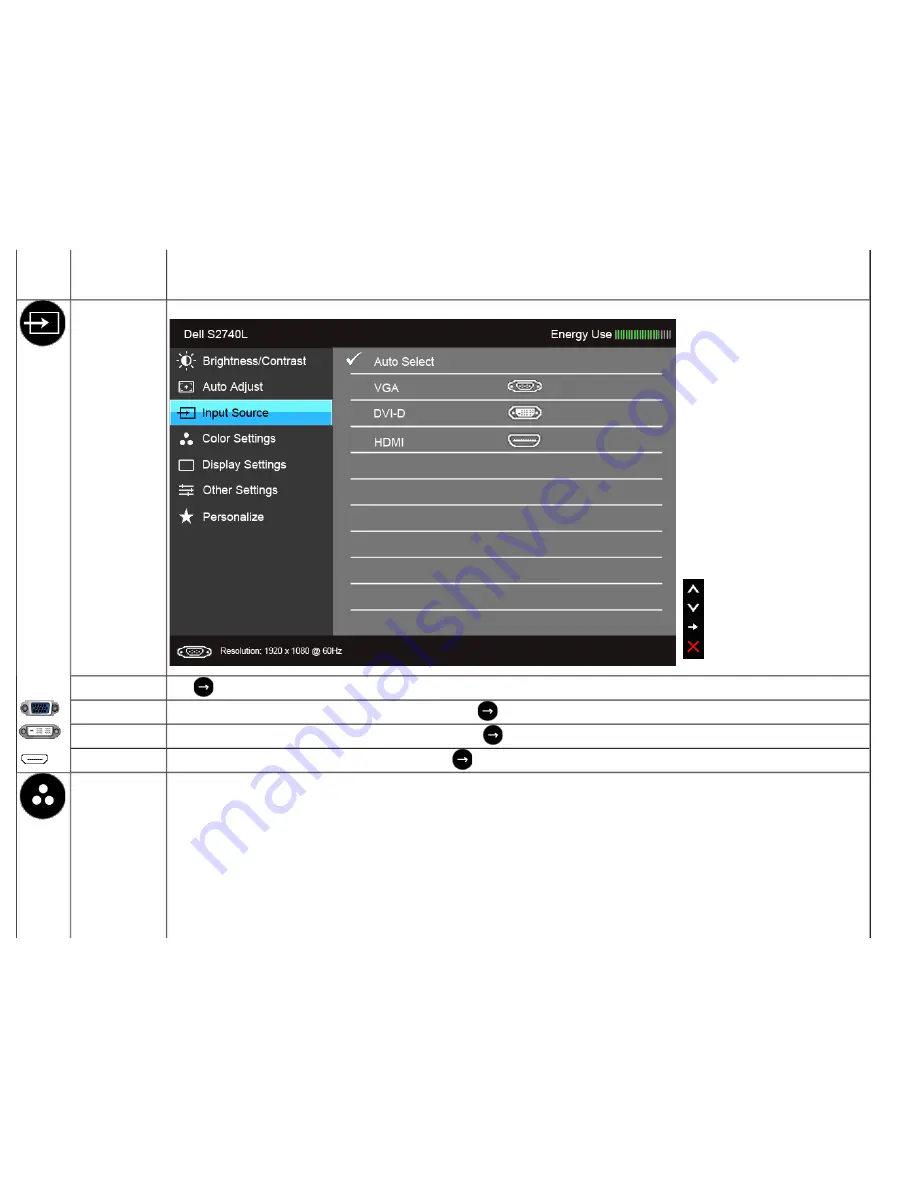
Input Source

Use the 

Input Source

 menu to select between the different video signals that may be connected to your monitor.


Auto Select

Press 

 to select 

Auto Select

, the monitor scans for available input sources.

VGA

Select the 

VGA

 input when you are using the analog (VGA) connector. Press 

 to select the VGA input source.

DVI-D

Select the 

DVI-D

 input when you are using the Digital (DVI) connector. Press 

 to select the DVI input source.

HDMI

Select the 

HDMI

 input when you are using the HDMI connector. Press 

 to select the HDMI input source. 


Color Settings

Use 

Color Settings

 to adjust the color setting mode.

Summary of Contents for S2740L

Page 1: ...tion in the United States and or other countries Intel is a registered trademark of Intel Corporation in the U S and other countries and ATI is a trademark of Advanced Micro Devices Inc ENERGY STAR is a registered trademark of the U S Environmental Protection Agency As an ENERGY STAR partner Dell Inc has determined that this product meets the ENERGY STAR guidelines for energy efficiency Other trad...

Page 2: ...ictly forbidden Trademarks used in this text Dell and the DELL logo are trademarks of Dell Inc Microsoft and Windows are either trademarks or registered trademarks of Microsoft Corporation in the United States and or other countries Intel is a registered trademark of Intel Corporation in the U S and other countries and ATI is a trademark of Advanced Micro Devices Inc ENERGY STAR is a registered tr...

Page 3: ...el Policy Maintenance Guidelines Package Contents Your monitor ships with the components shown below Ensure that you have received all the components and contact Dell if something is missing NOTE Some items may be optional and may not ship with your monitor Some features or media may not be available in certain countries NOTE To set up with any other stand please refer to the respective stand setu...

Page 4: ...Stand Base Power Cable Power Adapter VGA Cable DVI Cable optional ...

Page 5: ...VESA 100 mm mounting holes for flexible mounting solutions Plug and play capability if supported by your system On Screen Display OSD adjustments for ease of set up and screen optimization Software and documentation media includes an Information File INF Image Color Matching File ICM Dell Display Manager software application and product documentation Energy Saver feature for Energy Star compliance...

Page 6: ...Identifying Parts and Controls Front View Front panel controls Label Description 1 Function buttons For more information see Operating the Monitor 2 Power On Off button with LED indicator ...

Page 7: ...nt kit 100 mm x 100 mm 2 Regulatory label List the regulatory approvals 3 Stand release button Release stand from monitor 4 Service tag label Refer to this label to contact Dell for express service 5 Barcode serial number label Refer to this label if you need to contact Dell for technical support 6 Cable management slot Use to organize cables by placing them through the slot ...

Page 8: ...ect your computer HDMI cable 3 DVI connector Connect your computer DVI cable 4 VGA connector Connect your computer VGA cable 5 DC power cord connector Connect the power cable 6 USB upstream port Connect the USB cable that came with your monitor to the monitor and the computer Once this cable is connected you can use the USB connectors on ...

Page 9: ...ensions 68 6 cm 27 inch diagonal viewable image size Preset display area Horizontal Vertical 597 9 mm 23 54 inches 336 3 mm 13 24 inches Pixel pitch 0 311 mm Viewing angle 178 vertical typical 178 horizontal typical Luminance output Panel 300 cd m Typ Monitor 270 cd m Typ Contrast ratio 1000 to 1 typical 8M to 1 typical Dynamic Contrast On Faceplate coating Glare with hard coating 3H Backlight LED...

Page 10: ... Preset Display Modes S2740L Display Mode Horizontal Frequency kHz Vertical Frequency Hz Pixel Clock MHz Sync Polarity Horizontal Vertical VESA 720 x 400 31 5 70 1 28 3 VESA 640 x 480 31 5 60 0 25 2 VESA 640 x 480 37 5 75 0 31 5 VESA 800 x 600 37 9 60 3 40 0 VESA 800 x 600 46 9 75 0 49 5 VESA 1024 x 768 48 4 60 0 65 0 VESA 1024 x 768 60 0 75 0 78 8 VESA 1152 x 864 67 5 75 0 108 0 VESA 1280 x 1024 ...

Page 11: ...ite On adapter PA 1041 71 100 VAC to 240 VAC 50 Hz or 60 Hz 3 Hz 1 2 A Max Output voltage current Output 12 VDC 3 33 A Inrush current 120 V 30 A Max 240 V 60 A Max Qualified Compatible AC DC adapters CAUTION To avoid damage to the monitor use only the adapter designed for this particular Dell monitor Manufacturer Model Polarity Delta ADP 40DD BA Lite On PA 1041 71TP LF Physical Characteristics Mod...

Page 12: ...ut stand assembly For wall mount or VESA mount considerations no cables 5 28 kg 11 62 lb Weight of stand assembly 1 65 kg 3 64 lb Front frame gloss 90 100 gloss unit Environmental Characteristics Model S2740L Temperature Operating 0 C to 40 C Non operating Storage 20 C to 60 C 4 F to 140 F Shipping 20 C to 60 C 4 F to 140 F Humidity Operating 10 to 80 non condensing Non operating Storage 5 to 90 n...

Page 13: ...ature VESA Modes Horizontal Sync Vertical Sync Video Power Indicator Power Consumption Normal operation Active Active Active White 35 W maximum 21 W typical Active off mode Inactive Inactive Blanked Amber Less than 0 5 W Switch off Off Less than 0 5 W The OSD functions only in the normal operation mode When any button is pressed in the Active off mode one of the following messages will be displaye...

Page 14: ...d Signal Cable 1 Video Red 2 Video Green 3 Video Blue 4 GND 5 Self test 6 GND R 7 GND G 8 GND B 9 Computer 5 V 3 3 V 10 GND sync 11 GND 12 DDC data 13 H sync 14 V sync 15 DDC clock DVI Connector Pin 24 pin Side of the Connected Signal Cable ...

Page 15: ...8 Floating 9 TMDS RX1 10 TMDS RX1 11 TMDS Ground 12 Floating 13 Floating 14 5 V 3 3 V power 15 Self test 16 Hot Plug Detect 17 TMDS RX0 18 TMDS RX0 19 TMDS Ground 20 Floating 21 Floating 22 TMDS Ground 23 TMDS Clock 24 TMDS Clock HDMI Connector Pin 19 pin Side of the Connected Signal Cable ...

Page 16: ...The monitor automatically provides the computer system with its Extended Display Identification Data EDID using Display Data Channel DDC protocols so the system can configure itself and optimize the monitor settings Most monitor installations are automatic you can select different settings if desired For more information about changing the monitor settings see Operating the Monitor Universal Seria...

Page 17: ... speed 12 Mbps 2 5 W Max each port Low speed 1 5 Mbps 2 5 W Max each port USB Upstream Connector Pin Number 4 pin Side of the Connector 1 DMU 2 VCC 3 DPU 4 GND USB Downstream Connector Pin Number 4 Pin Side of the Signal Cable 1 VCC 2 DMD 3 DPD 4 GND ...

Page 18: ...monitor WARNING Before cleaning the monitor unplug the monitor power cable from the electrical outlet For best practices follow the instructions in the list below while unpacking cleaning or handling your monitor To clean your anti static screen lightly dampen a soft clean cloth with water If possible use a special screen cleaning tissue or solution suitable for the anti static coating Do not use ...

Page 19: ...and base are detached when the monitor is shipped from the factory 1 Assemble the stand riser to stand base a Attach the stand riser to the stand base b Tighten the thumbscrew below the stand base 2 Attach the stand assembly to the monitor a Place the monitor on a soft cloth or cushion near the edge of desk b Fit the two tabs on the upper part of the stand to the groove on the back of the monitor ...

Page 20: ...t your monitor to the computer 1 Turn off your computer and disconnect the power cable Connect the blue VGA cable from your monitor to the computer NOTE If your computer supports a DVI HDMI connector connect the DVI HDMI cable to the monitor and the DVI HDMI connector to your computer The HDMI cable can be purchased separately ...

Page 21: ...r the VGA display connector cable to the corresponding video port on the back of your computer Do not connect all cables on the same computer Use all cables only when they are connected to different computers with appropriate video systems Connecting the white DVI cable Connecting the blue VGA cable ...

Page 22: ...ur monitor setup 1 Connect the upstream USB port cable supplied to an appropriate USB port on your computer See bottom view for details 2 Connect the USB peripherals to the downstream USB ports on the monitor 3 Plug the power cables for your computer and monitor into a nearby outlet 4 Turn on the monitor and the computer If your monitor displays an image installation is complete If it does not dis...

Page 23: ...nize all cables as shown above Removing the Monitor Stand NOTE To prevent scratches on the LCD screen while removing the stand ensure that the monitor is placed on a soft clean surface NOTE This is applicable for a monitor with a stand When any other stand is bought please refer to the respective stand setup guide for the set up instructions ...

Page 24: ...To remove the stand 1 Place the monitor on a flat surface 2 Press and hold the stand release button 3 Lift the stand up and away from the monitor Wall Mounting Optional Screw dimension M4 x 10 mm ...

Page 25: ... Philips crosshead screwdriver to remove the four screws securing the plastic cover 4 Attach the mounting bracket from the wall mounting kit to the monitor 5 Mount the monitor on the wall by following the instructions that comes with the wall mounting kit NOTE For use only with UL listed wall mount bracket with minimum weight load bearing capacity of 5 88 kg Back to Contents Page ...

Page 26: ... Setting the Maximum Resolution Using the Tilt Power On the Monitor Press the button to turn on the monitor Using the Front Panel Controls Use the control buttons on the front of the monitor to adjust the characteristics of the image being displayed As you use these buttons to adjust the controls an OSD shows the numeric values of the characteristics as they change ...

Page 27: ...button to launch the On Screen Display OSD and select the OSD Menu See Accessing the Menu System 4 Exit Use this button to go back to the main menu or exit the OSD main menu 5 Power with power light indicator Use the Power button to turn the monitor On and Off The white light indicates the monitor is On and fully functional An amber light indicates the power save mode Front Panel Button Use the bu...

Page 28: ...go back to the previous menu Using the On Screen Display OSD Menu Accessing the Menu System NOTE If you change the settings and then either proceed to another menu or exit the OSD menu the monitor automatically saves those changes The changes are also saved if you change the settings and then wait for the OSD menu to disappear 1 Press the button to launch the OSD menu and display the main menu Mai...

Page 29: ...or Main Menu for digital DVI input ...

Page 30: ...or Main Menu for digital HDMI input ...

Page 31: ... list of all the options available for the monitor 3 Press the button once to activate the highlighted option 4 Press and button to select the desired parameter 5 Press to enter the slide bar and then use the and buttons according to the indicators on the menu to make your changes 6 Select the button to return to the main menu Icon Menu and Submenus Description Brightness Contrast Use this menu to...

Page 32: ...button to increase the contrast and press the button to decrease the contrast min 0 max 100 The Contrast function adjusts the degree of difference between darkness and lightness on the monitor screen Auto Adjust Even though your computer recognizes your monitor on startup the Auto Adjustment function optimizes the display settings for use with your particular setup Auto Adjustment allows the monit...

Page 33: ...monitor Auto Select Press to select Auto Select the monitor scans for available input sources VGA Select the VGA input when you are using the analog VGA connector Press to select the VGA input source DVI D Select the DVI D input when you are using the Digital DVI connector Press to select the DVI input source HDMI Select the HDMI input when you are using the HDMI connector Press to select the HDMI...

Page 34: ... RGB Select this option if your monitor is connected to a computer or DVD player using the VGA and DVI cable YPbPr Select this option if your monitor is connected to a DVD player by YPbPr to VGA or YPbPr to DVI cable or if the DVD color output setting is not RGB ...

Page 35: ...ads color settings ideal for movies Game Loads color settings ideal for most gaming applications Text Loads brightness and sharpness settings ideal for viewing texts Warm Increase the color temperature The screen appears warmer with a red yellow tint Cool Decreases the color temperature The screen appears cooler with a blue tint Custom Color Allows you to manually adjust the color settings Press t...

Page 36: ... to 100 Press to increase the monochrome appearance of the video image Press to increase the colorful appearance of the video image NOTE Saturation adjustment is available only when you select Movie or Game preset mode Demo Mode Splits the screen into two for viewing the images under the normal and enhanced Movie preset mode side by side You can also press and simultaneously to enable disable this...

Page 37: ... for VGA input Sharpness This feature can make the image look sharper or softer Use or to adjust the sharpness from 0 to 100 Pixel Clock The Phase and Pixel Clock adjustments allow you to adjust your monitor to your preference Use or to adjust for best image quality Phase If satisfactory results are not obtained using the Phase adjustment use the Pixel Clock coarse adjustment and then use Phase fi...

Page 38: ...ust the slider in 1 second increments from 5 to 60 seconds Menu Lock Controls user access to adjustments When Lock is selected no user adjustments are allowed All buttons are locked NOTE Lock function Either soft lock through the OSD menu or hard lock press and hold the button above the power button for 10 seconds Unlock function Only hard unlock press and hold the button above the power button fo...

Page 39: ...LCD Conditioning Helps reduce minor cases of image retention Depending on the degree of image retention the program may take some time to run You can enable this feature by selecting Enable ...

Page 40: ...ry Reset Reset all OSD settings to the factory preset values Personalize Users can choose a feature from Preset Modes Brightness Contrast Auto Adjust Input Source or Aspect Ratio and set it as a shortcut key ...

Page 41: ... compensate for LED aging OSD Warning Messages When the Energy Smart or Dynamic Contrast feature is enabled in these preset modes Game or Movie the manual brightness adjustment is disabled When the monitor does not support a particular resolution mode you will see the following message ...

Page 42: ...itor Recommended mode is 1920 x 1080 You will see the following message before the DDC CI function is disabled When the monitor enters the Power Save mode the following message appears Activate the computer and wake up the monitor to gain access to the OSD If you press any button other than the power button one of the following messages will appear depending on the selected input VGA DVI D HDMI in...

Page 43: ... HDMI input is selected and the corresponding cable is not connected a floating dialog box as shown below appears or or It is recommended that you use the supplied power adapter If not you will see the message as shown below ...

Page 44: ...ter complete one of the following procedures If you have a Dell desktop or portable computer Go to support dell com enter your service tag and download the latest driver for your graphics card If you are using a non Dell computer portable or desktop Go to the support site for your computer and download the latest graphic drivers Go to your graphics card website and download the latest graphic driv...

Page 45: ...NOTE The stand is detached when the monitor is shipped from the factory Back to Contents Page ...

Page 46: ... the computer To ensure proper Self Test operation remove all Digital white connector and the Analog blue connector cables from the back of computer 3 Turn on the monitor The floating dialog box should appear on screen against a black background if the monitor cannot sense a video signal and is working correctly While in self test mode the power LED remains white Also depending upon the selected i...

Page 47: ...lue black white and text screens The test is complete when the text screen appears To exit press Button 4 again If you do not detect any screen abnormalities upon using the built in diagnostic tool the monitor is functioning properly Check the video card and computer In Store Demo To enter InStore OSD Mode Detach Disconnect all cables Make sure the monitor is in On mode Press and hold Button 2 and...

Page 48: ...trols via OSD Perform monitor self test feature check and determine if these lines are also in self test mode Check for bent or broken pins in the video cable connector Run the built in diagnostics NOTE When using DVI D HDMI input the Pixel Clock and Phase adjustments are not available Synchronization Problems Screen is scrambled or appears torn Reset the monitor to Factory Settings Perform Auto A...

Page 49: ... does not fill the entire screen The picture cannot fill the height or width of the screen Due to different video formats aspect ratio of DVDs the monitor may display in full screen Run the built in diagnostics NOTE When choosing DVI D mode the Auto Adjust function will not be available Universal Serial Bus USB Specific Problems Specific Symptoms What You Experience Possible Solutions USB interfac...

Page 50: ...nce Contacting Dell For customers in the United States call 800 WWW DELL 800 999 3355 NOTE If you do not have an active Internet connection you can find contact information on your purchase invoice packing slip bill or Dell product catalog Dell provides several online and telephone based support and service options Availability varies by country and product and some services may not be available i...

Page 51: ... switch to classic desktop 2 Right click on the desktop and click Screen Resolution 3 Click the Dropdown list of the Screen Resolution and select 1920 x 1080 4 Click OK If you do not see the recommended resolution as an option you may need to update your graphics driver Please choose the scenario below that best describes the computer system you are using and follow the given steps 1 If you have a...

Page 52: ...upport dell com enter your service tag and download the latest driver for your graphics card 2 After installing the drivers for your graphics adapter attempt to set the resolution to 1920 x 1080 again NOTE If you are unable to set the resolution to 1920 x 1080 please contact Dell to inquire about a graphics adapter that supports these resolutions Back to Contents Page ...

Page 53: ...d Settings 5 Identify your graphics controller supplier from the description at the top of the window e g NVIDIA ATI Intel etc 6 Refer to the graphic card provider website for updated driver for example http www ATI com OR http www NVIDIA com 7 After installing the drivers for your graphics adapter attempt to set the resolution to 1920 x 1080 again NOTE If you are unable to set the recommended res...

Reviews: