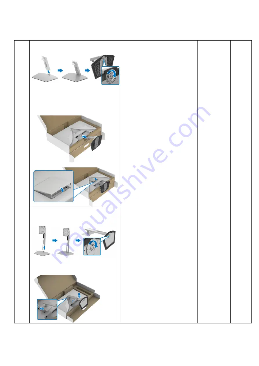
background image

- 16 - 


S2721D: 


S2721D: 

To assemble Stand and VESA 
screw cover with Monitor 
 
1.  Align and place the stand riser 

on the stand base 
 

2.  Open the screw handle at the 

bottom of the stand base and 
turn it clockwise to secure the 
stand assembly 

 
3.  Close the screw handle. 
 
4.  Align and insert the stand 

assembly bracket into the 
groove on the back of the 
display until it locks in place. 


5.  Install the VESA screw cover. 


S2721DS: 


S2721DS: 

To assemble Stand with Monitor 
 
1.  Align and place the stand riser 

on the stand base 
 

2.  Open the screw handle at the 

bottom of the stand base and 
turn it clockwise to secure the 
stand assembly 
 

3.  Close the screw handle. 


4.  Align and slide the tabs on the 

stand riser into the VESA slot. 
 

5.  Press the stand down until it 

snaps into place. 


Summary of Contents for S2721DB

Page 1: ...Simplified Service Manual S2721DB S2721DSB Version 01 Date 2021 03 08 ...

Page 2: ...SAFETY General Safety 3 1 2 SAFETY General Power Safety 5 2 Exploded view diagram with list of items 6 3 Wiring connectivity diagram 8 4 Disassembly and Assembly Procedures 9 4 1 Disassembly SOP 9 4 2 Assembly SOP 13 5 Trouble shooting instructions 17 ...

Page 3: ...r place equipment so close together that it is subject to recalculated or preheated air NOTE Review the weight limits referenced in your computer documentation before placing a monitor or other devices on top of your computer Ensure that nothing rests on your equipment s cables and that the cables are not located where they can be stepped on or tripped over Ensure that all cables are connected to ...

Page 4: ...ponents inside your equipment Under certain conditions ESD may build up on your body or an object such as a peripheral and then discharge into another object such as your computer To prevent ESD damage you should discharge static electricity from your body before you interact with any of your equipment s internal electronic components such as a memory module You can protect against ESD by touching...

Page 5: ...s risk of electric shock and or fire Ensure that the ground prong of the power plug is inserted into the mating ground contact of the power strip Be sure to grasp the plug not the cable when disconnecting equipment from an electric socket If your equipment uses an AC adapter Use only the Dell provided AC adapter approved for use with this device Use of another AC adapter may cause a fire or explos...

Page 6: ... Q ty 1 ASSY DECO 1 2 BTN OSD 1 3 PCBA CTRL BD 1 4 MF 1 5 Panel 1 6 PCBA SPS BD 1 7 PCBA I F BD 1 8 ASSY SHD 1 9 SPK 2 1 10 ASSY RC 1 11 ASSY STAND COLUMN 1 12 ASSY STAND BASE 1 13 ASSY COVER VESA 1 14 Power cable 1 15 HDMI cable 1 1 3 9 12 11 10 8 7 6 5 4 2 13 14 15 ...

Page 7: ...SSY DECO 1 2 BTN OSD 1 3 PCBA CTRL BD 1 4 MF 1 5 Panel 1 6 PCBA SPS BD 1 7 PCBA I F BD 1 8 ASSY SHD 1 9 SPK 2 1 10 ASSY RC 1 11 ASSY STAND COLUMN 1 12 ASSY STAND BASE 1 13 Power cable 1 14 HDMI cable 1 1 2 4 5 6 7 8 9 10 11 12 3 13 14 ...

Page 8: ... 8 3 Wiring connectivity diagram FFC 2 FFC 3 FFC 1 Wire 1 ...

Page 9: ...ayout 4 Prepare the implement equipment material as bellow 1 Working table 2 Philips head screwdriver 3 Glove 4 Cleaning cloth 5 ESD protection Item Picture Operation Tool Notes 1 Removing the monitor stand S2720D 1 Place the monitor on a soft cloth or cushion 2 Press the dimple on the VESA cover to release it from the back of the display 3 Using a long screwdriver push the release latch located i...

Page 10: ...d assembly up and away from the monitor 2 S2721D 1 Unlock 2 Stand screws 2 Unlock 4 screws on Rear Cover Philips head screwdriver Torsion of RC screw 8 5 1 0kgf Stand screw 4 5kgf S2721DS 1 Unlock 4 screws on Rear Cover Philips head screwdriver Torsion of RC screw 8 5 1 0kgf 3 1 Follow the sequence to disassemble Rear Cover from the monitor ...

Page 11: ...1 Tear off AL Tape 2 Pull out CTRL FFC from I F BD 3 Pull out backlight wire from SPS BD 6 1 Unlock 4 Main SHD screws 2 Pull out FFC LVDS from the Panel 3 Take off Main SHD from Panel Philips head screwdriver Torsion of Main SHD screw 6 7kgf ...

Page 12: ... 12 7 1 Disassemble Safety Mylar from SPS BD 8 1 Unlock 8 PCBA screws 2 Disassemble I F BD SPS BD from Main SHD 3 Pull out FFC LVDS from I F BD Philips head screwdriver Torsion of PCB screw 6 7kgf ...

Page 13: ...hilips head screwdriver 3 Glove 4 Cleaning cloth 5 ESD protection Item Picture Operation Tools Notes 1 1 Place Main SHD on the worktable 2 Assemble SPS BD into Main SHD 3 Insert FFC LVDS into I F BD 4 Insert SPS BD to I F BD wire into I F BD 5 Assemble I F BD into Main SHD 6 Lock 8 PCBA screws 7 Assemble Safety Mylar on SPS BD Philips head screwdriver Torsion of PCB screw 6 7kgf ...

Page 14: ... Philips head screwdriver Torsion of Main SHD screw 6 7kgf 3 1 Insert CTRL FFC into I F BD and arrange CTRL FFC 2 Insert backlight wire into SPS BD 3 Stick 1 adhesive tape to fix backlight wire and CTRL FFC on Panel 4 Stick the AL Tape on Main SHD and Panel 4 1 Insert SPK wire into I F BD ...

Page 15: ... Cover to make it be assembled with Mid Frame tightly 6 S2721DS 1 Lock 4 screws on Rear Cover Philips head screwdriver Torsion of RC screw 8 5 1 0kgf S2721D 1 Lock 4 screws on Rear Cover 2 Lock 2 Stand screws Philips head screwdriver Torsion of RC screw 8 5 1 0kgf Stand screw 4 5kgf ...

Page 16: ...ert the stand assembly bracket into the groove on the back of the display until it locks in place 5 Install the VESA screw cover S2721DS S2721DS To assemble Stand with Monitor 1 Align and place the stand riser on the stand base 2 Open the screw handle at the bottom of the stand base and turn it clockwise to secure the stand assembly 3 Close the screw handle 4 Align and slide the tabs on the stand ...

Page 17: ... 17 5 Trouble shooting instructions ...

Page 18: ... 18 ...

Page 19: ... 19 ...

Page 20: ... 20 ...

Page 21: ... 21 ...

Page 22: ... 22 ...

Page 23: ... 23 ...

Reviews: