4. Disassembly and Assembly Procedures
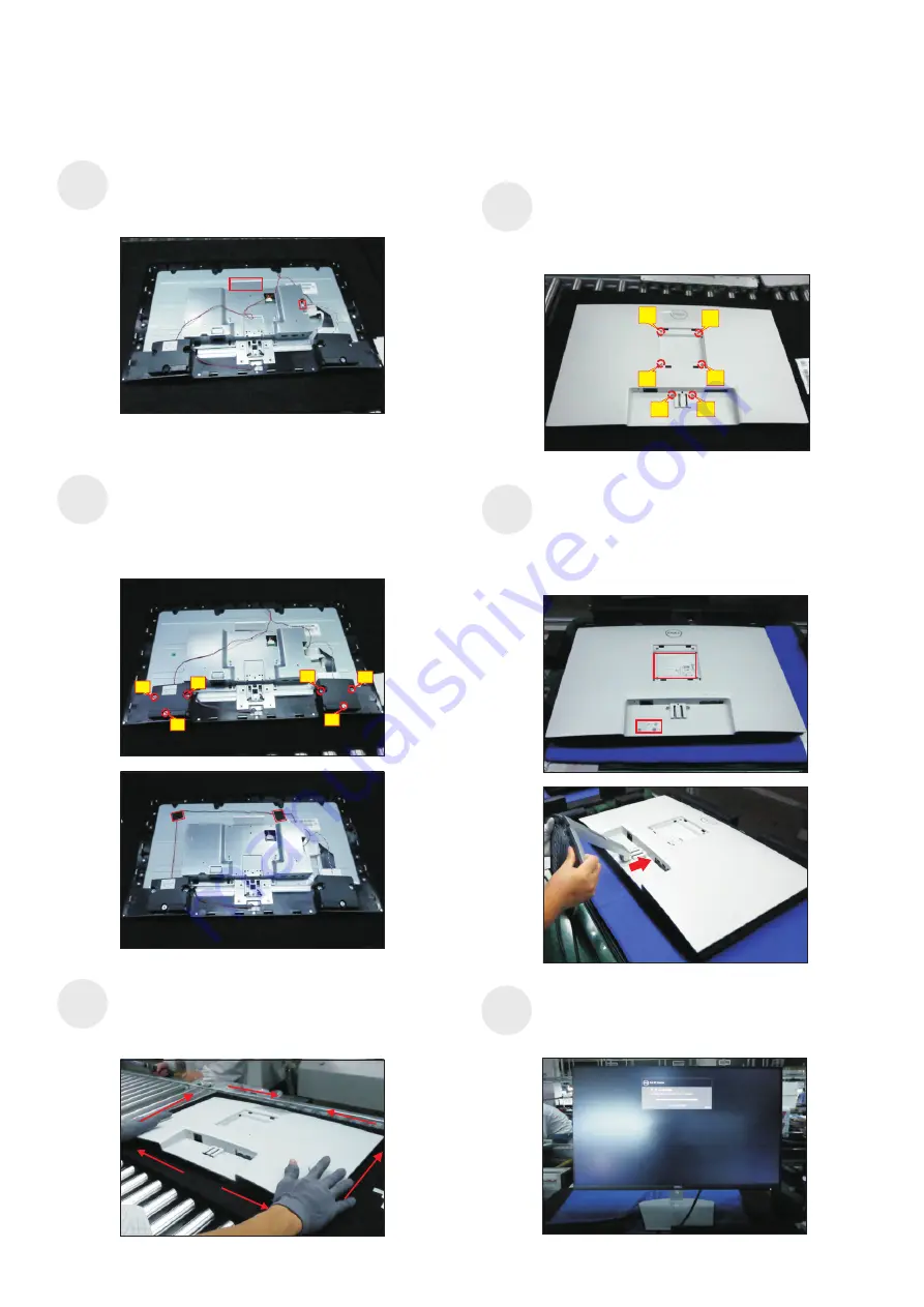
Use a Philips-head screwdriver to tighten 4pcs
screws for locking rear cover with the assembled
unit, to tighten 2pcs screws for locking the rear
cover with bracket chassis module.
(No.1~4 screw size=M4x11; Torque=7 8kgfxcm;
No.5~6 screw size=M4x8; Torque=7 8kgfxcm)
~
~
Take 1pcs rear cover, put down the rear cover
and push the rear cover on the positions marked
as the picture below shown for mechanisms
engagement.
S17
Take a pair of speakers to locate the probers of the
middle bezel, then connect the speaker cable to the
connector of the board. Paste 1pcs aluminum foil to
fix the bracket on the specific position.
S15
S18
Use a Philips-head screwdriver to tighten 6pcs
screws for locking the speakers with middle bezel.
Settle the cable and then fix the speaker’s cables
with 2pcs acetate tapes on the specific position as
the picture below shown.
(No.1~6 screw size=M3x8, Torque=5
~
6kgfxcm)
S16
2
3
4
1
L
front bezel with panel module , then provide power
supply and a video signal to the monitor, then turn
on the monitor for functionality check.
ift up the monitor
to checking the gap between the
S20
Stick 2pcs labels on the specific positions as the
picture below shown. Take 1pcs stand riser and
1pcs stand base, assemble the stand base with
stand riser, then rotate the screw clockwise to lock
the stand base and stand riser. Insert the stand-riser
into monitor groove until it snaps into its place.
S19
1
5
4
6
2
3
5
6


