


Memory
Dell Precision™ T7500 Service Manual
WARNING:
Before working inside your computer, read the safety information that shipped with your
computer. For additional safety best practices information, see the Regulatory Compliance Homepage
at www.dell.com/regulatory_compliance.
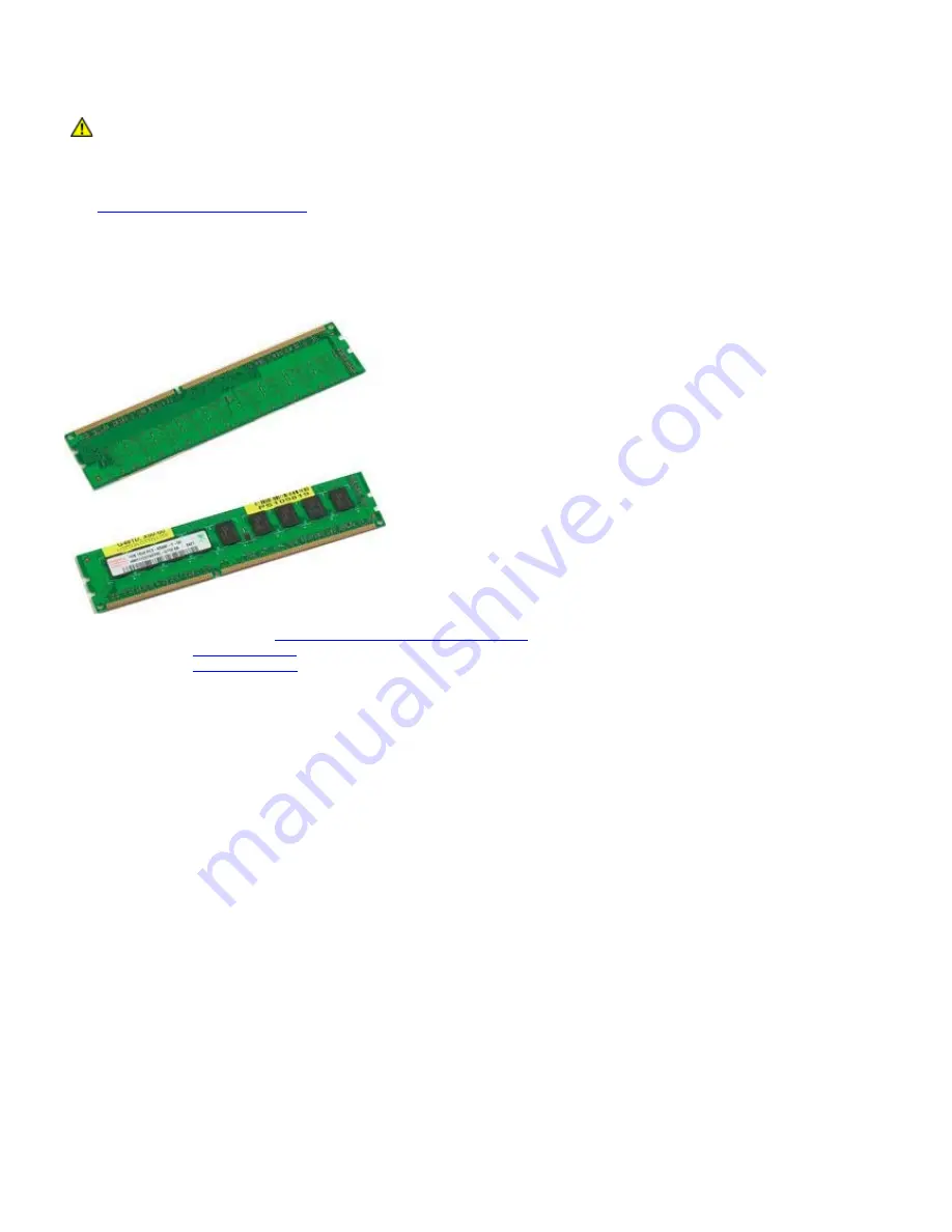
Your computer features an optional dual-processor riser to accommodate dual processor and expanded memory options
(see
Dual Processor Riser (Optional)
). Memory modules are removed from and installed into slots both on the system
board or on the optional dual-processor riser identically, although only the slots located on the system board are
illustrated below.
Removing the Memory Modules
1. Follow the procedures in
Before Working Inside Your Computer
.
2. Remove the
computer cover
.
3. Remove the
memory shroud
.
Summary of Contents for Precision T7500
Page 26: ...3 Pull the cover away from the computer 4 Remove the cover from the computer ...
Page 27: ......
Page 29: ...5 Remove the coin cell battery from the computer ...
Page 30: ......
Page 34: ......
Page 37: ...6 Repeat the process for the second hard drive cage ...
Page 38: ......
Page 41: ...7 Remove the fan assembly from the computer ...
Page 42: ......
Page 44: ...3 Remove the memory shroud from the computer ...
Page 47: ......
Page 50: ...6 Remove the chipset fan from the computer ...
Page 51: ......
Page 55: ......
Page 59: ......
Page 63: ......
Page 66: ......
Page 69: ......
Page 73: ...5 ...
Page 76: ...5 Remove the fan from the computer ...
Page 77: ......
Page 80: ......
Page 82: ...4 Loosen the four captive screws on the heat sink 5 Remove the heat sink from the computer ...
Page 83: ...6 Press down and out on the processor holder arm to release it 7 Lift the processor cover ...
Page 84: ...8 Remove the processor from the computer ...
Page 85: ......
Page 93: ...17 Open the dual processor cover 18 Remove the dual processor from the dual processor board ...
Page 94: ......
Page 96: ...5 Disconnect the data cable 6 Disconnect the USB cable ...
Page 98: ......
Page 100: ...8 Disconnect the rear fan cable 9 Disconnect the front panel audio cable ...
Page 101: ...10 Disconnect the intrusion switch cable 11 Disconnect the 1394 cable ...
Page 102: ...12 Disconnect the floppy cable 13 Disconnect the I O panel cable ...
Page 103: ...14 Disconnect the hard drive fan cable 15 Disconnect any hard drive data cables ...
Page 104: ...16 Disconnect the power supply cable 17 Disconnect the optical drive data cable ...
Page 105: ...18 Disconnect the power supply data cable 19 Remove the nine screws securing the system board ...
Page 107: ...22 Remove the system board from the chassis ...
Page 108: ......


