9. Remove the
10. Remove the
11. Remove the
12. Remove the
13. Remove the
14. Remove the
15. Remove the
.
16. Remove the
17. Remove the
.
18. Remove the
19. Remove the
.
20. Remove the
.
21. Remove the
.
22. Remove the
.
23. Remove the
.
24. Remove the
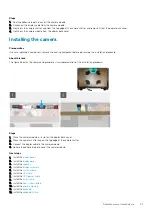
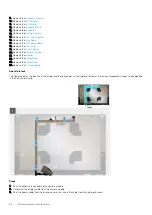
About this task
The figure indicates the location of the display cable and provides a visual representation of the removal procedure. Images to be uploaded
in the next review cycle.
Steps
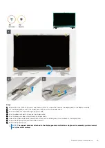
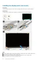
1. Peel the adhesive tape covering the camera module.
2. Disconnect the display cable from the camera module.
3. Peel the display cable from the display cover and unroute the cable from the routing channels
94
Demontowanie i montowanie
Summary of Contents for Precision 7750
Page 1: ...Precision 7750 Service Manual Regulatory Model P44E Regulatory Type P44E001 May 2020 Rev A00 ...
Page 22: ...22 Demontowanie i montowanie ...
Page 25: ...Demontowanie i montowanie 25 ...
Page 66: ...66 Demontowanie i montowanie ...
Page 75: ...Demontowanie i montowanie 75 ...
Page 77: ...Demontowanie i montowanie 77 ...


