background image

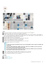
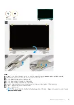
Steps

1.

NOTE:

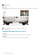
 Before installing the display assembly, ensure that the display hinges are opened to a 140-degree angle

against the display assembly, to fit the display assembly to the palmrest.

Align the screw holes on the hinges on the display assembly to the screw holes on the palmrest.

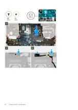
2. Replace the eight (M2.5x2.5) screws to secure the hinges to the palmrest.
3. Replace the (M2x5) screw to secure the display bracket to the palmrest.
4. Connect the display cable to the connector on the system board.
5. Replace the (M2x5) screw to secure the Darwin bracket.
6. Adhere the WWAN cables and Darwin cables to the palmrest.

Next steps

1. Install the 

heat-sink assembly

.

2. Install the 

primary memory

.

3. Install the 

keyboard

.

4. Install the 

keyboard lattice

.

5. Install the 

WLAN card

.

6. Install the 

WWAN card

.

7. Install the 

secondary memory

.

8. Install the 

SIM card

.

9. Install the 

primary M.2 SSD

.

10. Install the 

battery

.

11. Install the 

base cover

.

12. Install the 

secondary M.2 SSD

.

78

Demontowanie i montowanie

Summary of Contents for Precision 7750

Page 1: ...Precision 7750 Service Manual Regulatory Model P44E Regulatory Type P44E001 May 2020 Rev A00 ...

Page 2: ...rzętu lub utraty danych i przedstawia sposoby uniknięcia problemu PRZESTROGA Napis OSTRZEŻENIE informuje o sytuacjach w których występuje ryzyko uszkodzenia sprzętu obrażeń ciała lub śmierci 2020 Dell Inc lub podmioty zależne Wszelkie prawa zastrzeżone Dell EMC i inne znaki towarowe są znakami towarowymi firmy Dell Inc lub jej spółek zależnych Inne znaki towarowe mogą być znakami towarowymi ich wł...

Page 3: ...anie karty sieci SD 17 Drzwiczki dysku SSD 17 Removing SSD door 17 Installing SSD door 18 Dodatkowy dysk SSD M 2 19 Removing the secondary M 2 Solid state drive 19 Installing the secondary M 2 SSD module 20 pokrywa dolna 21 Removing the base cover 21 Installing the base cover 24 Akumulator 26 Środki ostrożności dotyczące akumulatora litowo jonowego 26 Removing the battery 26 Installing the battery...

Page 4: ...er button assembly with fingerprint reader 47 Installing the power button assembly with fingerprint reader 48 Rama wewnętrzna 49 Removing the inner frame 49 Installing the inner frame 50 Obudowa czytnika kart Smart 51 Removing the smart card reader 51 Installing the smart card reader 52 Przycisk tabliczki dotykowej 53 Removing the Touchpad buttons 53 Installing the Touchpad buttons 54 Czytnik kart...

Page 5: ...lling the display hinge non touch 88 Kamera 90 Removing the camera non touch 90 Installing the camera 91 Płyta czujnika zbliżeniowego 92 Wymontowywanie płytki czujnika zbliżeniowego 92 Instalowanie płytki czujnika zbliżeniowego 93 Kabel wyświetlacza 93 Removing the display cable 93 Installing the display cable 95 Display back cover 96 Replacing the display cable 96 4 Rozwiązywanie problemów 98 Del...

Page 6: ...iednio w dokumentacji produktu lub na telefoniczne polecenie zespołu wsparcia technicznego Uszkodzenia wynikające z napraw serwisowych nieautoryzowanych przez firmę Dell nie są objęte gwarancją Należy zapoznać się z instrukcjami dotyczącymi bezpieczeństwa dostarczonymi z produktem i przestrzegać ich OSTRZEŻENIE Aby uniknąć wyładowania elektrostatycznego należy odprowadzać ładunki z ciała za pomocą...

Page 7: ...uśpienia włączenie się po otrzymaniu zewnętrznego sygnału funkcja Wake on LAN Ponadto urządzenia te są wyposażone w inne zaawansowane funkcje zarządzania energią Odłączenie od zasilania oraz naciśnięcie i przytrzymanie przycisku zasilania przez 15 sekund powinno usunąć energię resztkową z płyty głównej Wyjmij akumulator z tabletu notebooka Połączenie wyrównawcze Przewód wyrównawczy jest metodą pod...

Page 8: ...ęt tymczasowo umieszczony na macie Fizyczne połączenie między paskiem na nadgarstek przewodem łączącym matą antystatyczną i sprzętem jest nazywane wiązaniem Należy używać wyłącznie zestawów serwisowych zawierających pasek na nadgarstek matę i przewód łączący Nie wolno korzystać z opasek bez przewodów Należy pamiętać że wewnętrzne przewody paska na nadgarstek są podatne na uszkodzenia podczas norma...

Page 9: ...podczas serwisowania części wrażliwe należy trzymać z dala od elementów izolacyjnych a wrażliwe elementy trzeba transportować w torbach antyelektrostatycznych Po zakończeniu serwisowania komputera Informacje na temat zadania Po zainstalowaniu lub dokonaniu wymiany sprzętu ale jeszcze przed włączeniem komputera podłącz wszelkie urządzenia zewnętrzne karty i kable Kroki 1 Podłącz do komputera kable ...

Page 10: ...ył stale rozpowszechniany jako jedyny właściwy standard interfejsu komputerów Sprzedano ok 6 miliardów urządzeń jednak potrzeba większej szybkości wciąż istniała w związku z rosnącą szybkością obliczeniową urządzeń oraz większym zapotrzebowaniem na przepustowość Odpowiedzią na potrzeby klientów jest standard USB 3 0 USB 3 1 pierwszej generacji który teoretycznie zapewnia 10 krotnie większą szybkoś...

Page 11: ... prędkość 4 8 Gb s standard może się znaleźć nawet w produktach które dotychczas nie były kojarzone ze złączami USB na przykład w zewnętrznych systemach pamięci masowej RAID Poniżej wymieniono niektóre produkty z interfejsem SuperSpeed USB 3 0 USB 3 1 pierwszej generacji Zewnętrzne stacjonarne dyski twarde USB 3 0 USB 3 2 pierwszej generacji Przenośne dyski twarde USB 3 2 pierwszej generacji Stacj...

Page 12: ...łane w technologii USB 2 lub USB 3 0 Na przykład tablet Nokia N1 z systemem Android ma złącze USB Type C ale cała łączność odbywa się w trybie USB 2 0 nawet nie USB 3 0 Technologie te są jednak blisko związane Thunderbolt przez USB Type C Thunderbolt jest interfejsem sprzętowym który może jednocześnie przesyłać dane obraz dźwięk i zasilanie za pośrednictwem jednego kabla Thunderbolt zapewnia połąc...

Page 13: ...ch protokół IP bez konieczności używania osobnego kabla Ethernet Kanał powrotny dźwięku umożliwia przesyłanie danych dźwiękowych z podłączonego do HDMI telewizora z wbudowanym tunerem do systemu dźwięku przestrzennego eliminując potrzebę stosowania osobnego kabla audio 3D definiuje protokoły we wy dla najważniejszych formatów obrazu 3D torując drogę do prawdziwie trójwymiarowych gier i filmów Typ ...

Page 14: ...peracyjnym DirectX 12 0 OpenGL 4 6 DisplayPort 1 4 DirectX 12 1 Obsługiwane rozdzielczości i maksymalne częstotliwości odświeżania Hz Maks w trybie cyfrowym jedno złącze DisplayPort 1 4 7680 x 4320 8k przy 30 Hz mDP Type C do DP Maks w trybie cyfrowym dwa złącza DisplayPort 1 4 7680 x 4320 8k przy 60 Hz mDP Type C do DP Liczba obsługiwanych wyświetlaczy Maksymalnie 4 wyświetlacze NVIDIA Quadro RTX...

Page 15: ...st MHz GPU base clock 14000 MHz Estimated Maximum Power 100 W Display Support eDP mDP HDMI Type C Maximum Color Depth Up to 10 bit color Operating Systems Graphics Video API Support DirectX 12 0 OpenGL 4 6 DisplayPort 1 4 DirectX 12 1 Supported Resolutions and Max Refresh Rates Hz Max Digital Single DisplayPort 1 4 7680 x 4320 8k 30 Hz mDP Type c to DP Max Digital Dual DisplayPort 1 4 7680 x 4320 ...

Page 16: ...ems Graphics Video API Support DirectX 12 0 OpenGL 4 6 DisplayPort 1 4 DirectX 12 1 Supported Resolutions and Max Refresh Rates Hz Max Digital Single DisplayPort 1 4 7680 x 4320 8k 30 Hz mDP Type C to DP Max Digital Dual DisplayPort 1 4 7680 x 4320 8k 60 Hz mDP Type C to DP Numbers of Display Support Up to 4 displays 16 Technologia i podzespoły ...

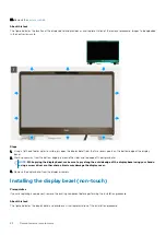
Page 17: ...procedury instalacji wymontuj wcześniej zainstalowany element Informacje na temat zadania Na ilustracji przedstawiono umiejscowienie i procedurę instalacji pokrywy dolnej Zdjęcia do przesłania w następnym cyklu przeglądu Kroki Wsuń kartę SD do gniazda aż usłyszysz kliknięcie Kolejne kroki 1 Wykonaj procedurę przedstawioną w sekcji Po zakończeniu serwisowania komputera Drzwiczki dysku SSD Removing ...

Page 18: ...he base cover Installing SSD door Prerequisites If you are replacing a component remove the existing component before performing the installation procedure About this task The figure indicates the location of the SSD door and provides a visual representation of the installation procedure 18 Demontowanie i montowanie ...

Page 19: ...kowy dysk SSD M 2 Removing the secondary M 2 Solid state drive Prerequisites NOTE For computers shipped with M 2 2280 or 2230 SSD installed in slot 6 1 Follow the procedure in before working inside your computer 2 Remove the SD card 3 Remove the SSD door About this task The figure indicates the location of the secondary M 2 SSD and provides a visual representation of the removal procedure Demontow...

Page 20: ...r M 2 2230 SSD a Remove the M 2 2230 SSD with its holder from the SSD carrier b Remove the M2x2 screw to secure the M 2 2230 SSD to its holder c Remove the SSD from the holder Installing the secondary M 2 SSD module Prerequisites NOTE For computers shipped with M 2 2280 or 2230 SSD installed in slot 6 If you are replacing a component remove the existing component before performing the installation...

Page 21: ...rmal plate to the M 2 SSD 5 Replace the SSD module in its slot on the computer 6 Replace the M2x3 screw to secure the SSD module in place Next steps 1 Install the SSD door 2 Install the SD card 3 Follow the procedure in after working inside your computer pokrywa dolna Removing the base cover Prerequisites 1 Follow the procedure in before working inside your computer 2 Remove the SD card About this...

Page 22: ...22 Demontowanie i montowanie ...

Page 23: ...en the base cover starting from bottom edge of the cover NOTE For models shipped without SmartCard reader pry open the base cover from the smart card reader slot Use your fingers to pry open the base cover as the use of plastic scribe or any other sharp objects may damage the base cover Demontowanie i montowanie 23 ...

Page 24: ...r on the system board Installing the base cover Prerequisites If you are replacing a component remove the existing component before performing the installation procedure About this task The figure indicates the location of the base cover and provides a visual representation of the installation procedure 24 Demontowanie i montowanie ...

Page 25: ...Demontowanie i montowanie 25 ...

Page 26: ...i akumulatora Nie wyginać akumulatora Nie wolno podważać akumulatora żadnymi narzędziami Podczas serwisowania tego produktu należy się upewnić że żadne śruby nie zostały zgubione ani nie znajdują się w nieodpowiednim miejscu ponieważ grozi to przypadkowym przebiciem lub uszkodzeniem baterii bądź innych komponentów systemu Jeśli akumulator litowo jonowy utknie w urządzeniu z powodu spuchnięcia nie ...

Page 27: ...the battery 3 Remove the battery away from the computer Installing the battery Prerequisites If you are replacing a component remove the existing component before performing the installation procedure About this task The figure indicates the location of the battery and provides a visual representation of the installation procedure Demontowanie i montowanie 27 ...

Page 28: ...in after working inside your computer Dysk SSD Removing the primary M 2 Solid state drive Prerequisites NOTE For computers shipped with M 2 2280 or 2230 SSD installed in slot 3 slot 4 and or slot 5 1 Follow the procedure in before working inside your computer 2 Remove the SD card 3 Remove the base cover About this task The figure indicates the location of the primary M 2 SSD and provides a visual ...

Page 29: ...t secures the M 2 SSD to the computer b Remove the M 2 SSD 4 For M 2 2230 SSD a Remove the M2x3 screw that secures the SSD module b Remove the SSD module from the computer c Remove the M2x2 screw that secures the SSD to SSD holder d Remove the SSD from the holder 5 Repeat the above steps to remove the other SSD modules in the computer Demontowanie i montowanie 29 ...

Page 30: ...remove the existing component before performing the installation procedure About this task The figure indicates the location of the primary M 2 SSD and provides a visual representation of the installation procedure Steps 1 For M 2 2280 SSD a Place the M 2 SSD onto its slot on the computer b Replace the M2x3 screw to secure the M 2 SSD to the computer 30 Demontowanie i montowanie ...

Page 31: ... computer Next steps 1 Install the base cover 2 Install the SD card 3 Follow the procedure in after working inside your computer Dodatkowy moduł pamięci Removing the secondary memory module Prerequisites 1 Follow the procedure in before working inside your computer 2 Remove the SD card 3 Remove the base cover About this task The figure indicates the location of the secondary memory module and prov...

Page 32: ...emory module firmly into the slot and press the memory module until it clicks into place NOTE If you do not hear the click remove the memory module and reinstall it Next steps 1 Install the base cover 2 Install the SD card 3 Follow the procedure in after working inside your computer SIM karta Removing the SIM card Prerequisites 1 Follow the procedure in before working inside your computer 2 Remove...

Page 33: ...pening 2 Filp the right edge of the SIM card cover to open it 3 Remove the SIM card from the SIM card slot Installing the SIM card Prerequisites If you are replacing a component remove the existing component before performing the installation procedure About this task The figure indicates the location of the SIM card and provides a visual representation of the installation procedure Demontowanie i...

Page 34: ...nstall the SD card 3 Follow the procedure in after working inside your computer Karta sieci WLAN Removing the WLAN card Prerequisites 1 Follow the procedure in before working inside your computer 2 Remove the SD card 3 Remove the base cover About this task The figure indicates the location of the WLAN card and provides a visual representation of the removal procedure 34 Demontowanie i montowanie ...

Page 35: ...emove the existing component before performing the installation procedure About this task The figure indicates the location of the WLAN card and provides a visual representation of the installation procedure Steps 1 Insert the WLAN card to the connector on the system board 2 Connect the antenna cables to the WLAN card 3 Align and place the WLAN card bracket above the WLAN card to secure the antenn...

Page 36: ...ecures the WWAN card bracket to the system board 2 Lift the WWAN card bracket from the WWAN card 3 Disconnect the antenna cables from the connector on the WWAN card 4 Slide and remove the WWAN card from its slot on the system board Installing the WWAN card Prerequisites If you are replacing a component remove the existing component before performing the installation procedure About this task The f...

Page 37: ... Kratka klawiatury Removing the keyboard lattice Prerequisites 1 Follow the procedure in before working inside your computer 2 Remove the SD card 3 Remove the base cover About this task The figure indicates the location of the keyboard lattice and provides a visual representation of the removal procedure Steps 1 Using a plastic scribe pry the top edge of the keyboard lattice starting from the rece...

Page 38: ...Steps 1 Align the keyboard lattice to its position on the keyboard 2 Press the edges on the keyboard lattice until it clicks into place Next steps 1 Install the base cover 2 Install the SD card 3 Follow the procedure in after working inside your computer Klawiatura Removing the keyboard Prerequisites 1 Follow the procedure in before working inside your computer 2 Remove the SD card 3 Remove the ba...

Page 39: ...rd to the palmrest 4 Pry the bottom edge of the keyboard and then work along the left and the right sides of the keyboard 5 Carefully unroute the keyboard backlight cable and the keyboard cable through the palmrest 6 Remove the keyboard from the system Installing the keyboard Prerequisites If you are replacing a component remove the existing component before performing the installation procedure A...

Page 40: ...em at 90 angle to access the keyboard and the keyboard backlight cables 5 Connect the keyboard backlight cable and the keyboard cable to the connectors on the system board NOTE Ensure that you fold the keyboard data cable in perfect alignment Next steps 1 Install the keyboard lattice 2 Install the battery 3 Install the base cover 4 Install the SD card 5 Follow the procedure in after working inside...

Page 41: ...he SD card 3 Remove the base cover 4 Remove the battery 5 Remove the keyboard lattice 6 Remove the keyboard About this task The figure indicates the location of the primary memory module and provides a visual representation of the removal procedure Steps 1 Remove the M2x3 screw that secures the memory shield in place Demontowanie i montowanie 41 ...

Page 42: ... component remove the existing component before performing the installation procedure About this task The figure indicates the location of the primary memory module and provides a visual representation of the installation procedure Steps 1 Align the notch on the memory module with the tab on the memory module slot 2 Slide the memory module firmly into the slot at an angle and press the memory modu...

Page 43: ...Follow the procedure in before working inside your computer 2 Remove the SD card 3 Remove the base cover 4 Remove the battery About this task The figure indicates the location of the heat sink assembly and provides a visual representation of the removal procedure Steps 1 Peel the power adapter cable from the heat sink assembly 2 Disconnect the two fan cables from the connectors on the system board...

Page 44: ...Align and insert the heat sink assembly into its slot on the computer 2 Tighten the eight captive screws to secure the heat sink assembly to the system board NOTE Tighten the captive screws in the order stamped onto the heat sink next to the screws 1 2 3 4 5 6 7 8 3 Connect the two fan cables to the connector on the system board 4 Adhere the power adapter cable on the heat sink assembly Next steps...

Page 45: ...emove the M2x3 screw that secures power adapter cable bracket 2 Remove the power adapter cable bracket from the computer 3 Lift the power adapter port from its slot on the palmrest 4 Unroute and remove the power adapter cable from the computer Installing the power adapter port Prerequisites If you are replacing a component remove the existing component before performing the installation procedure ...

Page 46: ...se cover 4 Install the SD card 5 Follow the procedure in after working inside your computer Płyta przycisku zasilania Removing the power button board Prerequisites 1 Follow the procedure in before working inside your computer 2 Remove the SD card 3 Remove the base cover 4 Remove the battery 5 Remove the heat sink assembly About this task The figure indicates the location of the power button board ...

Page 47: ...nto its slot on the computer 3 Replace the two M2x3 screws to secure the power button board 4 Adhere the power button board cable to the palmrest 5 Connect the power button board cable to the connector on the system board Next steps 1 Install the heat sink assembly 2 Install the battery 3 Install the base cover 4 Install the SD card 5 Follow the procedure in after working inside your computer Przy...

Page 48: ...ard cable from the palmrest 6 Remove the two M2x3 screws that secure the power button board to the computer 7 Remove the power button board with the power button board cable from the computer 8 Disconnect the power button board cable from the power button board Installing the power button assembly with fingerprint reader Prerequisites If you are replacing a component remove the existing component ...

Page 49: ...he power button daughter board 8 Replace the M2 5x2 5 screw to secure the power button assembly with fingerprint reader cable bracket in place Next steps 1 Install the heat sink assembly 2 Install the battery 3 Install the base cover 4 Install the SD card 5 Follow the procedure in after working inside your computer Rama wewnętrzna Removing the inner frame Prerequisites 1 Follow the procedure in be...

Page 50: ...sis 4 Remove the inner frame from the computer while carefully unthreading the keyboard cable and keyboard backlight cable through the opening on the inner frame Installing the inner frame Prerequisites If you are replacing a component remove the existing component before performing the installation procedure About this task The figure indicates the location of the inner frame and provides a visua...

Page 51: ...N card 2 Install the WWAN card 3 Install the primary M 2 SSD 4 Install the battery 5 Install the base cover 6 Install the SD card 7 Follow the procedure in after working inside your computer Obudowa czytnika kart Smart Removing the smart card reader Prerequisites 1 Follow the procedure in before working inside your computer 2 Remove the SD card 3 Remove the base cover 4 Remove the battery 5 Remove...

Page 52: ... smart card reader cable from the touchpad 4 Remove the two M2x2 5 screws that secure the smart card reader to the computer 5 Remove the smart card reader from the computer Installing the smart card reader Prerequisites If you are replacing a component remove the existing component before performing the installation procedure About this task The figure indicates the location of the smart card read...

Page 53: ... 1 Install the WLAN card 2 Install the WWAN card 3 Install the primary M 2 SSD 4 Install the inner frame 5 Install the battery 6 Install the base cover 7 Install the SD card 8 Follow the procedure in after working inside your computer Przycisk tabliczki dotykowej Removing the Touchpad buttons Prerequisites 1 Follow the procedure in before working inside your computer 2 Remove the SD card 3 Remove ...

Page 54: ...nect the touchpad buttons cable from the connector on the touchpad 3 Remove the two M2x2 5 screws that secure the touchpad buttons to the palmrest 4 Remove the touchpad buttons from the palmrest Installing the Touchpad buttons Prerequisites If you are replacing a component remove the existing component before performing the installation procedure About this task The figure indicates the location o...

Page 55: ...e touchpad Next steps 1 Install the inner frame 2 Install the WLAN card 3 Install the WWAN card 4 Install the primary M 2 SSD 5 Install the battery 6 Install the base cover 7 Install the SD card 8 Follow the procedure in after working inside your computer Czytnik kart SD Removing SD card reader Prerequisites 1 Follow the procedure in before working inside your computer 2 Remove the SD card 3 Remov...

Page 56: ...ottom side of the computer 3 Remove the M2 5x2 5 screw that secures the SD card reader in place 4 Slide and remove the SD card reader with its cable out of the computer Installing SD card reader Prerequisites If you are replacing a component remove the existing component before performing the installation procedure About this task The figure indicates the location of the SD card reader and provide...

Page 57: ...Install the primary M 2 SSD 5 Install the inner frame 6 Install the battery 7 Install the base cover 8 Install the SD card 9 Follow the procedure in after working inside your computer Przycisk zasilania Removing the power button Prerequisites 1 Follow the procedure in before working inside your computer 2 Remove the SD card 3 Remove the base cover 4 Remove the battery 5 Remove the heat sink assemb...

Page 58: ...e computer Installing the power button Prerequisites If you are replacing a component remove the existing component before performing the installation procedure About this task The figure indicates the location of the power button and provides a visual representation of the installation procedure 58 Demontowanie i montowanie ...

Page 59: ... computer Zestaw przycisku zasilania z czytnikiem linii papilarnych Removing the power button assembly with fingerprint reader Prerequisites 1 Follow the procedure in before working inside your computer 2 Remove the SD card 3 Remove the base cover 4 Remove the battery 5 Remove the heat sink assembly 6 Remove the power button board assembly with fingerprint reader About this task The figure indicat...

Page 60: ...this task The figure indicates the location of the power button and provides a visual representation of the installation procedure Steps 1 Place the power button assembly with fingerprint reader into its slot on the computer 2 Replace the two M2x3 screws to secure the power button assembly with fingerprint reader in place Next steps 1 Install the power button board assembly with fingerprint reader...

Page 61: ...tor outside the end of the connector head to unlock the GPU power cable connector from the GPU card 2 Slightly slide the GPU power cable connector outwards to disconnect the GPU power cable from the GPU card 3 Repeat the above steps to disconnect the GPU power cable from the system board 4 Peel the GPU power cable from the computer Installing the GPU power cable Prerequisites If you are replacing ...

Page 62: ...e keyboard lattice 3 Install the battery 4 Install the base cover 5 Install the SD card 6 Follow the procedure in after working inside your computer Płyta systemowa Removing the system board Prerequisites 1 Follow the procedure in before working inside your computer 2 Remove the SD card 3 Remove the SSD door 4 Remove the secondary M 2 SSD 5 Remove the base cover 6 Remove the battery 7 Remove the p...

Page 63: ...heat sink assembly 16 Remove the inner frame About this task The figure indicates the location of the system board and provides a visual representation of the removal procedure Images to be uploaded in the next review cycle NOTE For discrete models shipped with GPU card Demontowanie i montowanie 63 ...

Page 64: ...ra power adapter cable touchpad cable USH daughter board cable for models shipped with a USH daughter board and power button board cable from the system board 5 Remove the M2x3 screw that secures the Darwin cable bracket in place 6 Remove the Darwin cable bracket 7 Disconnect the Darwin cables from the connectors on the system board 8 Remove the six M2x3 screws that secure the three beam connector...

Page 65: ...ystem board 14 Remove the four M2x5 screws that secure the system board to the computer 15 Pry the coin cell battery located under the system board from the palmrest while lifting the system board 16 Remove the system board from the computer Installing the system board Prerequisites If you are replacing a component remove the existing component before performing the installation procedure About th...

Page 66: ...66 Demontowanie i montowanie ...

Page 67: ...e connector 8 Replace the M2x3 screw to secure the Darwin cable bracket to the system board 9 Connect the beam connectors on the system board NOTE For UMA models replace the two M2x3 screws to secure the single beam connector in place on the bottom side of the system For discrete models shipped with a 128 MB vram GPU card replace the four M2x3 screws to secure the two beam connector in place on th...

Page 68: ...ontuj podstawowy dysk SSD M 2 8 Wymontuj kartę SIM 9 Wymontuj pamięć dodatkową 10 Wymontuj kartę sieci WWAN 11 Wymontuj kartę sieci WLAN 12 Wymontuj kratkę klawiatury 13 Wymontuj klawiaturę 14 Odłącz kabel zasilania karty graficznej 15 Wymontuj pamięć podstawową 16 Wymontuj zestaw radiatora 17 Wymontuj ramę wewnętrzną 18 Wymontuj płytę główną Informacje na temat zadania Ilustracja przedstawia umie...

Page 69: ...Zainstaluj podstawowy dysk SSD M 2 13 Zainstaluj baterię 14 Zainstaluj pokrywę dolną 15 Zainstaluj dodatkowy dysk SSD M 2 16 Zainstaluj drzwiczki karty SSD 17 Zainstaluj kartę SD 18 Wykonaj procedurę przedstawioną w sekcji Po zakończeniu serwisowania komputera Głośnik Removing the speaker Prerequisites 1 Follow the procedure in before working inside your computer 2 Remove the SD card 3 Remove the ...

Page 70: ...able to the palmrest 2 Pry the speaker module from its slot on the top edge of the palmrest 3 Remove the speaker module from the computer Installing the speaker Prerequisites If you are replacing a component remove the existing component before performing the installation procedure About this task The figure indicates the location of the speaker and provides a visual representation of the installa...

Page 71: ...e inner frame 5 Install the heat sink assembly 6 Install the primary memory 7 Install the keyboard 8 Install the keyboard lattice 9 Install the WLAN card 10 Install the WWAN card 11 Install the secondary memory 12 Install the SIM card 13 Install the primary M 2 SSD 14 Install the battery 15 Install the base cover 16 Install the secondary M 2 SSD 17 Install the SSD door 18 Install the SD card 19 Fo...

Page 72: ... WWAN card 11 Remove the WLAN card 12 Remove the keyboard lattice 13 Remove the keyboard 14 Remove the primary memory 15 Remove the heat sink assembly 16 Remove the inner frame 17 Remove the GPU power cable 18 Remove the GPU card 19 Remove the system board About this task The figure indicates the location of the speaker and provides a visual representation of the removal procedure Images to be upl...

Page 73: ...almrest NOTE Ensure that the middle cap is secured in place by the two pegs on the palmrest 2 Replace the four M2x3 screws to secure the middle cap in place Next steps 1 Install the system board 2 Install the GPU card 3 Install the GPU power cable 4 Install the inner frame 5 Install the heat sink assembly 6 Install the primary memory 7 Install the keyboard 8 Install the keyboard lattice 9 Install ...

Page 74: ...card 3 Remove the SSD door 4 Remove the secondary M 2 SSD 5 Remove the base cover 6 Remove the battery 7 Remove the primary M 2 SSD 8 Remove the SIM card 9 Remove the secondary memory 10 Remove the WWAN card 11 Remove the WLAN card 12 Remove the keyboard lattice 13 Remove the keyboard 14 Remove the primary memory 15 Remove the heat sink assembly About this task The figure indicates the location of...

Page 75: ...Demontowanie i montowanie 75 ...

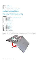
Page 76: ...ures the Darwin bracket 5 Peel and remove the WWAN cables and Darwin cables from the palmrest 6 Remove the eight M2 5x2 5 screws that secures the hinges to the palmrest 7 Remove the display assembly from the palmrest Installing the display assembly Prerequisites If you are replacing a component remove the existing component before performing the installation procedure About this task The figure in...

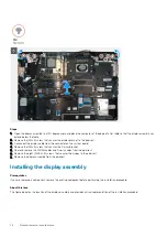
Page 77: ...Demontowanie i montowanie 77 ...

Page 78: ...cure the display bracket to the palmrest 4 Connect the display cable to the connector on the system board 5 Replace the M2x5 screw to secure the Darwin bracket 6 Adhere the WWAN cables and Darwin cables to the palmrest Next steps 1 Install the heat sink assembly 2 Install the primary memory 3 Install the keyboard 4 Install the keyboard lattice 5 Install the WLAN card 6 Install the WWAN card 7 Inst...

Page 79: ...he keyboard lattice 13 Remove the keyboard 14 Remove the primary memory 15 Remove the power adapter port 16 Remove the power button board 17 Remove the smart card reader 18 Remove the touchpad buttons 19 Remove the SD card reader 20 Remove the power button or power button assembly with fingerprint reader 21 Remove the heat sink assembly 22 Remove the inner frame 23 Remove the GPU power cable 24 Re...

Page 80: ...existing component before performing the installation procedure About this task The figure indicates the palmrest and before performing the pre installation parts procedures for any palmrest installation procedure Next steps 1 Install the display assembly 80 Demontowanie i montowanie ...

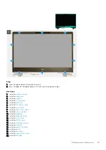
Page 81: ... the battery 24 Install the base cover 25 Install the secondary M 2 SSD 26 Install the SSD door 27 Install the SD card 28 Follow the procedure in after working inside your computer Osłona wyświetlacza Removing the display bezel non touch Prerequisites 1 Follow the procedure in before working inside your computer 2 Remove the SD card 3 Remove the SSD door 4 Remove the secondary M 2 SSD 5 Remove the...

Page 82: ...around the sides and top edge of the display bezel NOTE While prying the display bezel make sure to pry along the outside edge of the display bezel using your hands using a screw driver or other sharp objects may damage the display cover 3 Remove the display bezel from the display assembly Installing the display bezel non touch Prerequisites If you are replacing a component remove the existing com...

Page 83: ...ll the GPU card 6 Install the GPU power cable 7 Install the inner frame 8 Install the heat sink assembly 9 Install the primary memory 10 Install the keyboard 11 Install the keyboard lattice 12 Install the WLAN card 13 Install the WWAN card 14 Install the secondary memory 15 Install the SIM card 16 Install the primary M 2 SSD 17 Install the battery 18 Install the base cover 19 Install the secondary...

Page 84: ...y 10 Remove the WWAN card 11 Remove the WLAN card 12 Remove the keyboard lattice 13 Remove the keyboard 14 Remove the primary memory 15 Remove the heat sink assembly 16 Remove the inner frame 17 Remove the GPU power cable 18 Remove the GPU card 19 Remove the system board 20 Remove the display assembly 21 Remove the speaker 22 Remove the middle cap 23 Remove the display assembly 24 Remove the displ...

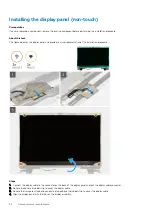
Page 85: ... the adhesive tapes that secures the display cable 5 Peel the adhesive rubber strip covering the display cable 6 Unlock the display cable connector and then disconnect the display cable from the back of the display panel 7 Remove the display panel form the display assembly 8 Remove the display panel NOTE The support brackets attached to the display panel are defined as a single service assembly pa...

Page 86: ... a visual representation of the installation procedure Steps 1 Connect the display cable to the connector on the back of the display panel and lock the display cable connector 2 Adhere the adhesive rubber strip to cover the display cable 3 Adhere the transparent tape and conductive tape above the rubber strip to cover the display cable 4 Align the display panel with the tabs on the display assembl...

Page 87: ...Install the base cover 21 Install the secondary M 2 SSD 22 Install the SSD door 23 Install the SD card 24 Follow the procedure in after working inside your computer Zawiasy wyświetlacza Removing the display hinge Prerequisites 1 Follow the procedure in before working inside your computer 2 Remove the SD card 3 Remove the SSD door 4 Remove the secondary M 2 SSD 5 Remove the base cover 6 Remove the ...

Page 88: ... Steps 1 Remove the eight M2 5x2 5 screws that secures the display hinges to the display assembly 2 Remove the display hinges Installing the display hinge non touch Prerequisites If you are replacing a component remove the existing component before performing the installation procedure About this task The figure indicates the display hinge and provides a visual representation of the installation p...

Page 89: ...Install the GPU power cable 8 Install the inner frame 9 Install the heat sink assembly 10 Install the primary memory 11 Install the keyboard 12 Install the keyboard lattice 13 Install the WLAN card 14 Install the WWAN card 15 Install the secondary memory 16 Install the SIM card 17 Install the primary M 2 SSD 18 Install the battery 19 Install the base cover 20 Install the secondary M 2 SSD 21 Insta...

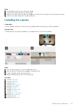
Page 90: ... the WLAN card 12 Remove the keyboard lattice 13 Remove the keyboard 14 Remove the primary memory 15 Remove the heat sink assembly 16 Remove the inner frame 17 Remove the GPU power cable 18 Remove the GPU card 19 Remove the system board 20 Remove the display assembly 21 Remove the speaker 22 Remove the display bezel 23 Remove the display panel About this task The figure indicates the location of t...

Page 91: ...a and provides a visual representation of the installation procedure Steps 1 Place the camera module in its slot on the display back cover 2 Place the camera shutter cap on the top edge of the camera shutter 3 Connect the display cable to the camera module 4 Adhere the adhesive tape to cover the camera module Next steps 1 Install the display panel 2 Install the display bezel 3 Install the speaker ...

Page 92: ...tkową 10 Wymontuj kartę sieci WWAN 11 Wymontuj kartę sieci WLAN 12 Wymontuj kratkę klawiatury 13 Wymontuj klawiaturę 14 Wymontuj pamięć podstawową 15 Wymontuj zestaw radiatora 16 Wymontuj ramę wewnętrzną 17 Odłącz kabel zasilania karty graficznej 18 Wymontuj kartę graficzną 19 Wymontuj płytę główną 20 Wymontuj zestaw wyświetlacza 21 Wymontuj głośnik 22 Wymontuj ramkę wyświetlacza 23 Wymontuj panel...

Page 93: ...7 Zainstaluj kabel zasilania karty graficznej 8 Zainstaluj ramę wewnętrzną 9 Zainstaluj zestaw radiatora 10 Zainstaluj pamięć podstawową 11 Zainstaluj klawiaturę 12 Zainstaluj kratkę klawiatury 13 Zainstaluj kartę sieci WLAN 14 Zainstaluj kartę sieci WWAN 15 Zainstaluj pamięć dodatkową 16 Zainstaluj kartę SIM 17 Zainstaluj podstawowy dysk SSD M 2 18 Zainstaluj baterię 19 Zainstaluj pokrywę dolną 2...

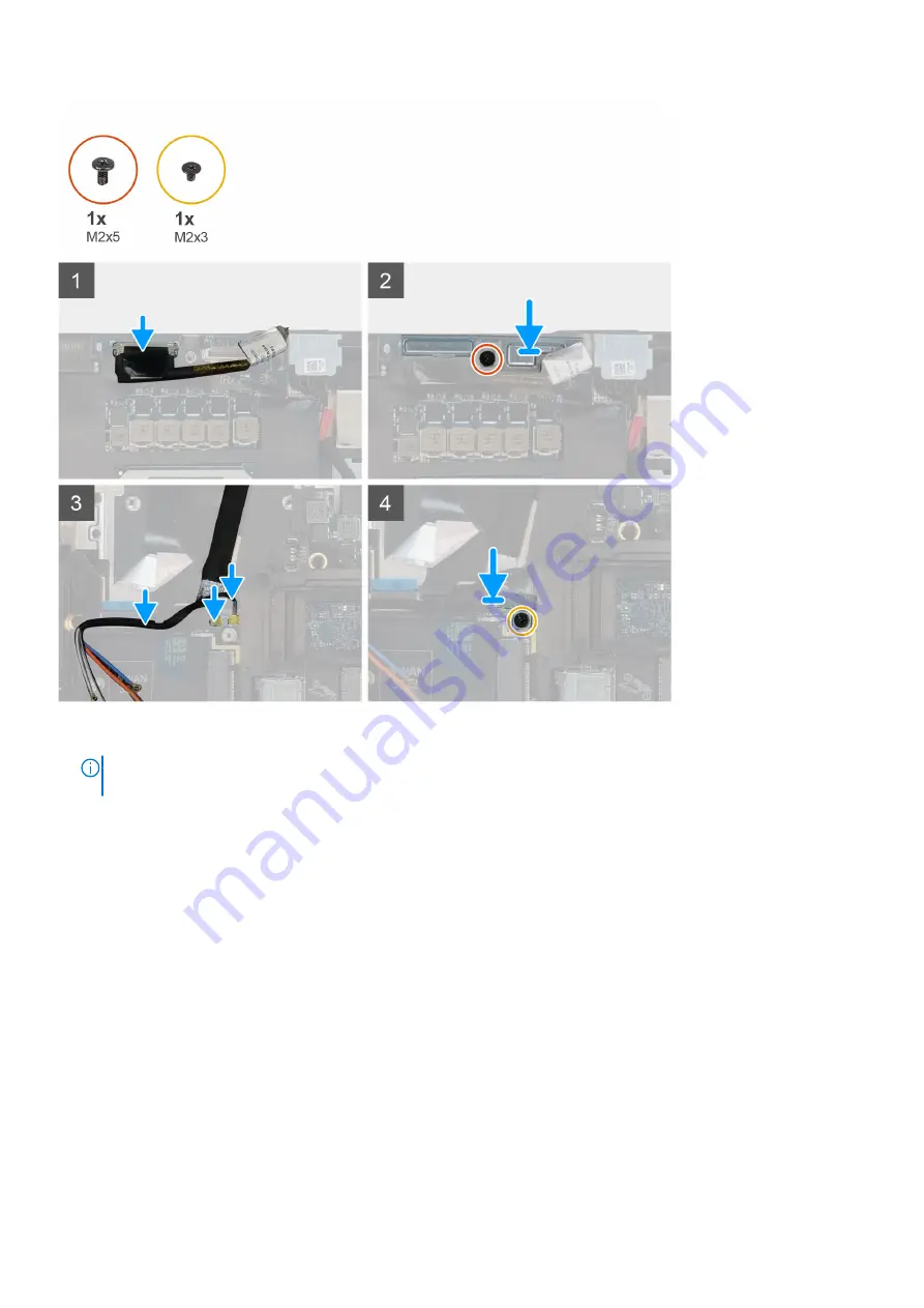
Page 94: ...mbly 21 Remove the speaker 22 Remove the display bezel 23 Remove the display panel 24 Remove the P sensor board About this task The figure indicates the location of the display cable and provides a visual representation of the removal procedure Images to be uploaded in the next review cycle Steps 1 Peel the adhesive tape covering the camera module 2 Disconnect the display cable from the camera mod...

Page 95: ...es a visual representation of the installation procedure Steps 1 Route and adhere the display cable on the display back cover 2 Connect the display cable to the connector on the camera module 3 Adhere the adhesive tape to cover the camera module Next steps 1 Install the P sensor board 2 Install the display panel 3 Install the display bezel 4 Install the speaker 5 Install the display assembly 6 Ins...

Page 96: ...d 3 Remove the SSD door 4 Remove the secondary M 2 SSD 5 Remove the base cover 6 Remove the battery 7 Remove the primary M 2 SSD 8 Remove the SIM card 9 Remove the secondary memory 10 Remove the WWAN card 11 Remove the WLAN card 12 Remove the keyboard lattice 13 Remove the keyboard 14 Remove the primary memory 15 Remove the heat sink assembly 16 Remove the inner frame 17 Remove the GPU power cable...

Page 97: ... card 11 Install the GPU power cable 12 Install the inner frame 13 Install the heat sink assembly 14 Install the primary memory 15 Install the keyboard 16 Install the keyboard lattice 17 Install the WLAN card 18 Install the WWAN card 19 Install the secondary memory 20 Install the SIM card 21 Install the primary M 2 SSD 22 Install the battery 23 Install the base cover 24 Install the secondary M 2 S...

Page 98: ...ą interwencji użytkownika Podczas wykonywania testów diagnostycznych nie należy odchodzić od terminala Dodatkowe informacje znajdują się w sekcji Rozwiązywanie problemów sprzętowych przy użyciu diagnostyki wbudowanej i online kody błędów SupportAssist ePSA ePSA lub PSA Uruchamianie przedrozruchowego testu diagnostycznego wydajności systemu SupportAssist Kroki 1 Włącz komputer 2 Kiedy komputer zacz...

Page 99: ...widłowo Wbudowany autotest szyny zasilania panelu wyświetlacza L BIST Informacje na temat zadania Kolejne kroki Test L BIST test szyny zasilania panelu wyświetlacza jest rozszerzeniem diagnostyki kodów błędów za pomocą pojedynczej diody LED i automatycznie uruchamia się podczas testu POST Test L BIST sprawdza czy ekran jest zasilany z płyty głównej Sprawdza on czy płyta główna zasila wyświetlacz p...

Page 100: ... light Indicates the power and battery charge status Solid white Power adapter is connected and the battery has more than 5 percent charge Amber Computer is running on battery and the battery has less than 5 percent charge Off Power adapter is connected and the battery is fully charged Computer is running on battery and the battery has more than 5 percent charge Computer is in sleep state hibernat...

Page 101: ...dule 2 6 Motherboard Chipset Error Flash latest BIOS version If problem persists replace the system board 2 7 LCD failure SBIOS message Flash latest BIOS version If problem persists replace the LCD module 2 8 LCD failure EC detection of power rail failure Replace the system board 3 1 CMOS battery failure Reset the CMOS battery connection If problem persists replace the RTC battery 3 2 PCI of Video...

Page 102: ...zyć i włączyć kartę Wi Fi Poniższa procedura zawiera instrukcje wyłączania i włączania karty Wi Fi UWAGA Niektórzy dostawcy usług internetowych ISP zapewniają urządzenie łączące funkcje routera i modemu Kroki 1 Wyłącz komputer 2 Wyłącz modem 3 Wyłącz router bezprzewodowy 4 Odczekaj 30 sekund 5 Włącz router bezprzewodowy 6 Włącz modem 7 Włącz komputer 102 Rozwiązywanie problemów ...

Page 103: ...e oraz telefonicznych Ich dostępność różni się w zależności od produktu i kraju a niektóre z nich mogą być niedostępne w regionie użytkownika Aby skontaktować się z działem sprzedaży pomocy technicznej lub obsługi klienta firmy Dell Kroki 1 Przejdź do strony internetowej Dell com support 2 Wybierz kategorię pomocy technicznej 3 Wybierz swój kraj lub region na liście rozwijanej Choose a Country Reg...

Reviews: