background image

6

Assembling a VLT

After you complete the initial configuration, the aggregator is powered up and operational.
VLT is limited to two aggregators of the same SKU in the same chassis. In the aggregator, VLT is 
supported only using a single inter chassis link (ICL) link between the two aggregators.

Cabling the VLT

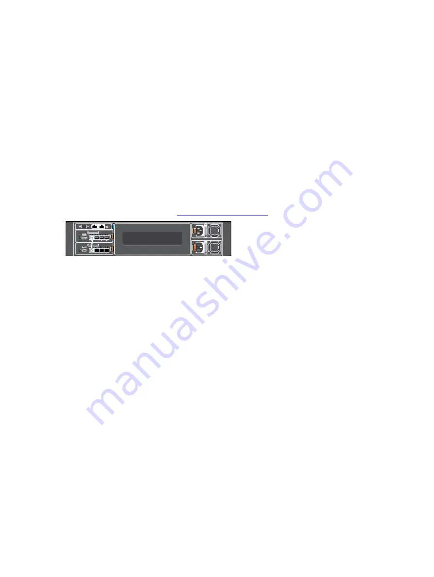
The following figure shows a VLT example using two aggregators in a chassis. The aggregators are 
connected to operate in VLT using only uplink port 9 which is a static ICL, when operating in 10G speed.

Prerequisite

: Before you attach the VLT cables, you must power up both aggregators with the default or 

reconfigured settings as described in 

Reconfiguring Default Settings

.

Figure 7. Switch VLT Using 10GbE Ports on Two Aggregators

Configuring and Bringing Up a VLT

1.

Connect the terminal to the console port on an aggregator. To access the CLI and configure the 

device in VLT mode, enter the following commands:

Login: username

Password: *****

Dell> enable

Dell# configure

Dell(conf)# stack-unit 0 iom-mode vlt

% You are about to configure Auto VLT to your IOA module, in 10G Uplink 

Mode please reload the IOA and then plug in the ICL cable for the changes 

to take effect.

Where 

stack-unit 0

 defines the default stack-unit number in the initial configuration of a switch.

2.

Repeat on the other aggregator in the VLT by entering the 

stack-unit 0 iom-mode vlt 

command and saving the configuration.

3.

Reboot each aggregator by entering the 

reload

 command in EXEC Privilege mode:

Dell# reload

System configuration has been modified. Save? [yes/no]: n  Proceed with 

reload [confirm yes/no]: y 

After you attach the cables in a VLT of an aggregator, follow these steps to configure and bring up 
the VLT.
To connect the VLT ports, use only the appropriate cable type based on the type of SKU; for 
example:

a.

Insert an SFP+ Multimode fiber/10g direct attach cable (DAC) into port 9 on the top aggregator.

Assembling a VLT

23

Summary of Contents for PowerEdge FN410S

Page 1: ...Dell PowerEdge FN 410S I O Aggregator Getting Started Guide ...

Page 2: ...problem WARNING A WARNING indicates a potential for property damage personal injury or death Copyright 2014 Dell Inc All rights reserved This product is protected by U S and international copyright and intellectual property laws Dell and the Dell logo are trademarks of Dell Inc in the United States and or other jurisdictions All other marks and names mentioned herein may be trademarks of their res...

Page 3: ...ge FX2 Server Chassis 16 Connecting a Console Terminal 16 Invoking the X Loader and U Boot CLIs 17 Reconfiguring Default Settings 17 Before You Start 17 Reconfiguration Using the CMC Interface 18 Reconfiguration Using the CLI 18 Aggregator Auto Configuration 19 Data Center Bridging Support 20 FCoE Connectivity 20 iSCSI Operation 20 Link Aggregation 20 Link Tracking 20 Configuring VLANs 21 Uplink L...

Page 4: ...7 Programmable MUX Mode 25 Configuring and Bringing Up the Programmable MUX Mode 25 8 Next Steps 27 9 Technical Specifications 29 ...

Page 5: ...ocumentation Hardware installation and power up instructions Installing the Dell PowerEdge FN 410S I O Aggregator Software configuration Dell Networking Operating System OS Configuration Guide for the Dell PowerEdge FN 410S I O Aggregator Command line interface Dell Networking OS Command Line Reference Guide for the Dell PowerEdge FN 410S I O Aggregator Latest updates Dell Networking OS Release No...

Page 6: ...6 ...

Page 7: ...guration Guide for the Dell PowerEdge FN 410S I O Aggregator which is available on the Dell Support website at http www dell com support manuals Product Description The aggregator is a multi layer 12x10Gigabit Ethernet switch that operates in a Dell PowerEdge FX2 server chassis which can support up to eight servers and two aggregator switches with four uplink interfaces each The Dell PowerEdge FX2...

Page 8: ...8 ...

Page 9: ...ws the aggregator front panel Figure 1 I O Aggregator Front Panel Port Numbering When installed in a server enclosure the Dell PowerEdge FN 410S I O Aggregator ports are numbered from 1 to 12 Ports from 1 to 8 are internal server facing ports Ports from 9 to 12 are external ports numbered from left to right on the switch To configure a port specify the slot from 0 to 5 default 0 and port number fr...

Page 10: ...ght emitting diodes LEDs and boot menu options You can also view status information through the show commands and with the simple network management protocol SNMP The aggregator includes LED displays as shown in the following figure Figure 3 System LED s on Front Panel The following table lists the LED definitions for the aggregator Table 2 System LED Displays System LED LED Color Display Descript...

Page 11: ...ort is down Solid green The port is up and can transmit traffic at maximum speed A SFP port can transmit at 10G Solid amber The port is up and is transmitting traffic at lower than maximum speed A SFP port is transmitting at 1G Activity LED Off No traffic is being transmitted or received on the port Blinking green Traffic is being transmitted or received on the port Hardware Overview 11 ...

Page 12: ...12 ...

Page 13: ... is unrestricted Unpacking the Aggregator When unpacking the aggregator ensure that the following items are included One FN I O Aggregator One USB type A to DB 9 female cable Getting Started Guide Safety and Regulatory Information Warranty and Support Information Software License Agreement Unpacking Steps NOTE Before unpacking the aggregator inspect the container and immediately report any evidenc...

Page 14: ...14 ...

Page 15: ...k the aggregator refer to the following flowchart for an overview of the steps you must follow to install the switch and perform the initial configuration Figure 4 Aggregator Installation and Configuration Flowchart Installing and Configuring the Aggregator 15 ...

Page 16: ...gs the switch up in operational mode Connecting a Console Terminal After the aggregator powers on complete all external cabling connections and connect a terminal to the switch to configure it To monitor and configure the aggregator with the serial console use the USB console port on the front panel of the switch to connect it to a VT100 terminal or to a computer running VT100 terminal emulation s...

Page 17: ...ssing any key After performing any of the X Loader or U Boot tasks the switch automatically reboots when you exit the CLI To continue with the boot process without entering either CLI do not press ESC key Reconfiguring Default Settings The I O Aggregator provides zero touch configuration with default user name root password calvin VLAN vlan1 and IP address for in band management DHCP IP address fo...

Page 18: ...y entering the user ID root and password calvin Then press Enter Login root Password Dell 2 At the EXEC mode prompt enter enable At the EXEC Privilege prompt enter configure to reach the configuration command mode Dell enable Dell configure Dell conf 3 At the configuration mode prompt enter the hostname name command to configure a hostname for the aggregator where name is a text string of up to 20...

Page 19: ... aggregator from a remote network enter the ip route subnet mask vlan 1 command where the subnet mask is an IP address in dotted decimal format A B C D and a subnet mask that defines the in band management network Dell conf ip route 10 1 1 0 24 vlan 1 11 By default broadcast storm control is enabled on the aggregator to limit unregistered unicast multicast and broadcast packets To disable storm co...

Page 20: ...thernet networks while preserving the Fiber Channel protocol The aggregator also provides zero touch configuration for FCoE connectivity The aggregator auto configures to match the FCoE settings used in the switches to which it connects through its uplink ports iSCSI Operation Support for iSCSI traffic is turned on by default when the aggregator powers up No configuration is required When an aggre...

Page 21: ...ration of all server facing ports ports from 1 to 8 The untagged VLAN used for the uplink LAG is always the default VLAN Server Facing LAGs The tagged VLAN membership of a server facing LAG is automatically configured based on the server facing ports that are members of the LAG The untagged VLAN of a server facing LAG is configured based on the untagged VLAN to which the lowest numbered server fac...

Page 22: ...o VLAN mode of operation in which all ports are members of all 4094 VLANs on a port enter the auto vlan command Dell conf interface tengigabitethernet 0 2 Dell conf if te 0 2 auto vlan 22 Installing and Configuring the Aggregator ...

Page 23: ...he CLI and configure the device in VLT mode enter the following commands Login username Password Dell enable Dell configure Dell conf stack unit 0 iom mode vlt You are about to configure Auto VLT to your IOA module in 10G Uplink Mode please reload the IOA and then plug in the ICL cable for the changes to take effect Where stack unit 0 defines the default stack unit number in the initial configurat...

Page 24: ...ed bandwidth capabilities If the aggregator switches all reboot at approximately the same time the aggregator with the highest MAC address is automatically elected as the primary switch The aggregator with the next highest MAC address is elected as secondary Perform VLAN and other software configuration for the VLT by connecting to the console port on each of the units 24 Assembling a VLT ...

Page 25: ... the following commands Login username Password Dell enable Dell configure Dell show system stack unit 0 iom mode Unit Boot Mode Next Boot 0 standalone standalone Dell Dell conf stack unit 0 iom mode programmable mux Where stack unit 0 defines the default stack unit number in the initial configuration of a switch 2 Delete the startup config file Dell delete startup config 3 Reboot each aggregator ...

Page 26: ...26 ...

Page 27: ...g the CLI use the attached console connection For remote in band management from a network management station enter the IP address of the default VLAN and log in to the switch to access the CLI In case of a Dell Networking OS upgrade you can check to see that the aggregator is running the latest Dell Networking OS version by entering the show version command For information about how to configure ...

Page 28: ...28 ...

Page 29: ...s Operating temperature 20 C h 36 F h Storage temperature 40 to 158 F 40 to 70 C Relative humidity Storage 5 to 95 RH with 33 C 91 F maximum dew point Atmosphere must be non condensing at all times Maximum thermal output 475 BTU hr Maximum altitude Operating Storage 3048 m 10 000 ft 12000m 39 370ft Table 5 Power Requirements Parameter Specifications Power supply 90 264 VAC 50 60 Hz Maximum current...

Reviews: