


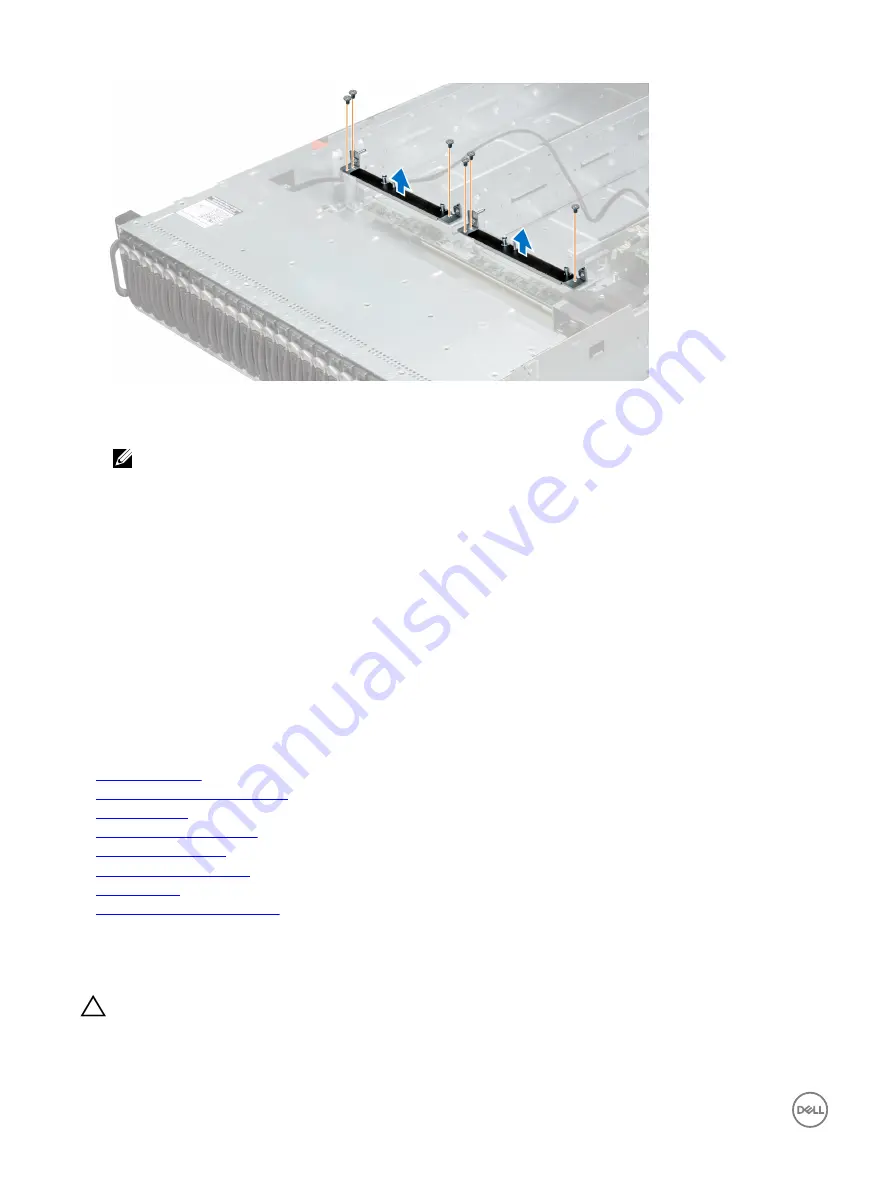
Figure 107. Removing the midplane holder
11.
Disconnect all the cables from the lower midplane.
NOTE: Note the routing of the cable on the chassis as you remove them from the system. Route these cables
properly when you replace them to prevent the cables from being pinched or crimped.
12.
Remove the screw that secures the power cable cover on the lower midplane.
13.
Remove the power cable cover from the lower midplane.
14.
Remove the screws that secure the power cables on the lower midplane.
15.
Remove the four power cables from the lower midplane.
16.
Remove the screws that secure the lower midplane to the chassis.
17.
Lift the lower midplane out of the chassis.
Next steps
1.
Install the midplanes.
2.
Install the cooling fan cage.
3.
Install the sleds into the enclosure.
4.
Follow the procedure listed in the After working inside your system section.
Related links
Safety instructions
Before working inside your system
Removing a sled
Removing a cooling fan cage
Installing the midplanes
Installing a cooling fan cage
Installing a sled
After working inside your system
Installing the midplanes
Prerequisites
CAUTION: Many repairs may only be done by a certified service technician. You should only perform troubleshooting and
simple repairs as authorized in your product documentation, or as directed by the online or telephone service and support
team. Damage due to servicing that is not authorized by Dell is not covered by your warranty. Read and follow the safety
instructions that are shipped with your product.
160
Summary of Contents for PowerEdge C6320p
Page 1: ...Dell PowerEdge C6320p Owner s Manual Regulatory Model B08S Series Regulatory Type B08S004 ...
Page 10: ...Figure 2 Supported configuration for the C6320p sled with an Intel Phi 72xx processor 10 ...
Page 11: ...Figure 3 Supported configuration for the C6320p sled with an Intel Phi 72xx F processor 11 ...
Page 25: ...Figure 16 Enclosure Service Tag location on the left front panel 25 ...
Page 106: ...Figure 55 Removing an expansion card filler bracket 106 ...


