background image

System Overview

1-5

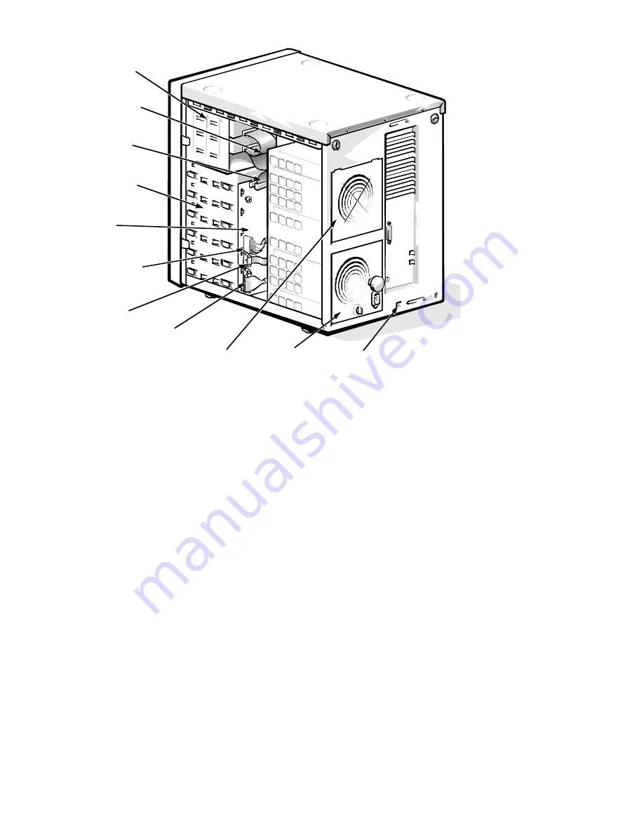
Figure 1-4.  Back/Right Internal View 

SCSI backplane 
board

external drive 
bays (4)

internal drive 
bays (6)

SCSI interface 
cable 
(Ultra/Wide)

SCSI power 
connector

server 
management 
connector

control panel connector

diskette interface
cable 
(Ultra/Narrow)

power supply (optional) or cooling fan

power supply 

SMB connector 

Summary of Contents for PowerEdge 4200 Series

Page 1: ... HOO 3RZHU GJH 6 VWHPV 6 59 0 18 ...

Page 2: ......

Page 3: ... HOO 3RZHU GJH 6 VWHPV 6 59 0 18 ...

Page 4: ...nd LANDesk are registered trademarks and MMX is a trademark of Intel Corporation IBM is a registered trademark of International Business Machines Corporation Microsoft Windows NT and MS DOS are registered trademarks of Microsoft Corporation Novell and NetWare are registered trademarks of Novell Inc Other trademarks and trade names may be used in this document to refer to either the entities claimi...

Page 5: ...m Unit 1 9 System Power Supply 1 9 Redundant Power Supply Option 1 10 Pin Assignments for the DC Power Connectors Nonredundant Systems 1 10 DC Power Distribution Nonredundant Systems 1 14 Pin Assignments for the DC Power Connectors Redundant Systems 1 15 Power Supply Paralleling Board 1 18 DC Power Distribution Redundant Systems 1 19 System Cooling 1 20 Cooling Fan Connectors 1 20 System Board Lay...

Page 6: ... Beep Codes 3 1 System Error Messages 3 3 Chapter 4 Removing and Replacing Parts 4 1 Recommended Tools 4 1 Precautionary Measures 4 2 Computer Covers 4 2 Front Bezel 4 4 Front Panel Inserts 4 4 Drives 4 5 Externally Accessible Drives 4 6 Hard Disk Drives 4 8 SCSI Backplane Board 4 10 Power Supply 4 11 Cooling Fan in Upper Power Supply Bay 4 12 Power Supply Paralleling Board 4 14 Power Connector Pa...

Page 7: ... 1 4 Back Right Internal View 1 5 Figure 1 5 I O Panel 1 6 Figure 1 6 Power Supply Connectors 1 11 Figure 1 7 Power Connector Panel 1 11 Figure 1 8 DC Power Connector J11 P1 1 12 Figure 1 9 DC Power Connectors J12 P2 J13 P3 and J14 P4 1 13 Figure 1 10 DC Power Connector J15 P5 1 13 Figure 1 11 Power Distribution Nonredundant System 1 14 Figure 1 12 DC Power Connector PWR1 1 15 Figure 1 13 DC Power...

Page 8: ...ctor Panel Removal Nonredundant Systems 4 15 Figure 4 15 Control Panel Removal 4 16 Figure 4 16 Cooling Fan Removal 4 17 Figure 4 17 System Board Removal 4 18 Figure 4 18 System Board Features 4 19 Figure 4 19 Expansion Card Connector Locations 4 20 Figure 4 20 Location of DIMM Sockets 4 21 Figure 4 21 DIMM Removal 4 21 Figure 4 22 DIMM Installation 4 22 Figure 4 23 Removing a Terminator Card 4 23...

Page 9: ...tions 1 24 Table 3 1 Beep Codes 3 1 Table 3 2 System Error Messages 3 3 Table A 1 System Setup Key Functions A 2 Table A 2 Main Menu Categories A 4 Table A 3 Boot Options Submenu Categories A 5 Table A 4 Advanced Menu Categories A 7 Table A 5 Security Menu Categories A 9 Table A 6 Exit Menu Categories A 11 ...

Page 10: ...niques Moreover only service techni cians trained in Dell removal and replacement methods should perform the procedures explained in this manual In addition to information provided in this manual and the User s Guide that came with the system Dell provides the Installation and Troubleshooting Guide for troubleshooting procedures and instructions on using the Dell di agnostics to test the computer ...

Page 11: ...erEdge 4200 system is equipped with a hot pluggable SCSI hard disk drive backplane ther mal and power supply monitoring features redundant fans ECC memory optional redundant power supplies and RAID capability The PowerEdge 4200 system is designed for freestanding operation but can also be rackmounted System Features The Dell PowerEdge 4200 system includes the following standard features Pentium II...

Page 12: ...ated super I O controller attached to the EISA bus that controls the bidirectional parallel port two serial ports and the diskette drive interface Integrated Ultra Wide and Ultra Narrow SCSI controllers Integrated server management circuitry that monitors critical system volt ages and temperatures as well as the operation of the system cooling fans SCSI CD ROM drive in an externally accessible dri...

Page 13: ...ection relative to the system is as shown in Figure 1 1 Figure 1 2 Front Panel Features back of computer right side left side front of computer power switch reset button hard disk drive online indicators 6 power indicator diskette drive access indicator hard disk drive activity indicators 6 hard disk drive failure indicators 6 ...

Page 14: ... system when the normal shutdown and restarting procedure fails Before using the reset button to initiate a hardware reset close any open application pro grams and files if possible If you are using MS DOS the system can be rebooted by pressing Ctrl Alt Del external drive bays 4 internal drive bays 6 system board microprocessor SEC cartridge heat sink assemblies 2 expansion slots intrusion detecti...

Page 15: ...ckplane board external drive bays 4 internal drive bays 6 SCSI interface cable Ultra Wide SCSI power connector server management connector control panel connector diskette interface cable Ultra Narrow power supply optional or cooling fan power supply SMB connector ...

Page 16: ...ll to guarantee compatibility All system memory operates at the speed of the slowest DIMM installed DIMMs of both capacities can be installed in the system However the larger capacity DIMMs should be installed in the top sockets beginning with socket DIMM_A with the smaller capacity DIMMs installed after wards in order toward socket DIMM_H keylocks 2 parallel port connector AC power receptacle ser...

Page 17: ... expansion card connectors and five PCI expansion card connectors The expansion card connectors are located on the system board see Figure 1 18 Integrated Server Management The system board contains integrated server management circuitry that moni tors critical system voltages and temperatures as well as the operation and speed of the system cooling fans The integrated server management circuitry ...

Page 18: ...le drives see Chapter 4 of this manual SCSI Configuration Guidelines Although SCSI devices are installed essentially the same way as other devices their configuration requirements are different To configure your SCSI sub system follow the general guidelines offered in the following subsections SCSI ID Numbers Each device attached to the 7860 Ultra Narrow SCSI host adapter must have a unique SCSI I...

Page 19: ...the documentation provided with the SCSI device for information on dis abling the device s terminator System Unit The following subsections provide service related information about the system unit System Power Supply The PowerEdge 4200 system contains either one 700 watt power supply non redundant configuration or two 700 watt power supplies redundant configuration Each installed power supply can...

Page 20: ...e redundant and nonredundant power configurations are provided later in this chapter Pin Assignments for the DC Power Connectors Nonredundant Systems The power supply output voltages for nonredundant systems can be measured at the connectors on the back of the power supply P1 P2 P3 P4 and P5 or at Table 1 1 DC Voltage Ranges Voltage Range Maximum Output Current 1 3 3 VDC 3 135 to 3 465 VDC 15 0 A ...

Page 21: ...J13 J14 and J15 Fig ures 1 6 and 1 7 show both sets of connectors Figure 1 6 Power Supply Connectors Figure 1 7 Power Connector Panel Figures 1 8 through 1 10 show the pinouts for the five DC power connectors J11 through J15 P1 P2 P4 P3 P5 J11 P1 J12 P2 J13 P3 J14 P4 J15 P5 ...

Page 22: ...that all power supply output voltages are within the ranges specified in Table 1 1 Figure 1 8 DC Power Connector J11 P1 13 WRGOOD 2 orange 14 15 16 17 18 19 20 21 22 J11 P1 5 VDC red 5 VDC red 5 VDC red 5 VDC red PSON 1 gray common black common black common black 5 VDC white 5 VDC red 23 24 3 3 VDC orange 3 3 VDC orange 1 2 3 4 5 9 10 5 VDC red 11 12 3 3 VDC orange 5 VDC sense red 6 7 8 common bla...

Page 23: ... 3 3 VDC orange 5 VDC red 5 VDC red 12 VDC yellow 5 VDC red J12 P2 J13 P3 J14 P4 10 11 12 13 14 15 16 5 VDC red common black common black common black 5 VDC red 17 18 common black common black common black common black 2 3 4 5 Good LED anode green Fail LED anode red 5 VDC red FAN_TACH gray J15 P5 1 6 7 8 9 10 3 3 VDC orange SW1 SW1 12 VDC red Good LED cathode green Fail LED cathode red ...

Page 24: ... 3 3 VDC 12 VDC 5 VDC 3 3 VDC 12 VDC 5 VDC 12 VDC 5 VDC P1 P2 P3 DDBP FD1 4 SCSI backplane six drive bays FLOPPY 1 2 3 4 5 6 CD ROM control panel speaker power on LED on off reset 3 X 6 LEDs system board power management logic RTC NVRAM PWRGOOD EISA1 through EISA3 PCI4 through PCI8 12 VDC 12 VDC 5 VDC 5 VDC 5 VFP 3 3 VDC PSON PWR 3 3 VDC 5 VDC 12 VDC 12 VDC 5 VDC 12 VDC 12 VDC 5 VDC battery batter...

Page 25: ... on the end of the wire bundles extending from these connectors PWR1 PWR2 PWR3 DDBP and FD1 FD4 see Figures 1 12 through 1 15 Figure 1 12 DC Power Connector PWR1 1 2 3 4 5 6 7 12 VDC blue PWR_STAT_BIT gray 5 VDC white 8 9 NC_ 12 sense BAT_V gray I 2 C_SDA gray I 2 C_SCL gray PRES_DET gray 5 VDC sense red PWR1 10 11 12 13 14 15 16 NC_NRLED common black POWER_GOOD gray common black NC_3INH 17 18 5 V...

Page 26: ...6 7 8 common black common black common black common black 17 18 19 20 3 3 VDC orange 3 3 VDC orange 5 VDC red 5 VDC red common black 12 VDC yellow 12 VDC yellow common black 3 3 VDC orange common black common black 1 2 3 4 5 6 7 5 VDC red 12 VDC yellow 5 VDC red 12 VDC yellow PWRSCSI DDBP 8 9 10 11 12 13 14 common black common black common black common black common black common black 12 VDC yellow...

Page 27: ...nected to FD1 and FD2 2 Wires 5 through 8 are connected to FD3 and FD4 Figure 1 15 DC Power Connector PWRFD FD1 FD4 2 3 4 1 5 VDC red PWRFD FD1 FD4 1 5 6 7 8 2 12 VDC yellow common black common black 12 VDC yellow common black common black 5 VDC red ...

Page 28: ...eling Board Figure 1 16 shows the location of the power connectors on the power supply paralleling board used in systems with redundant power supply systems Figure 1 16 Power Supply Paralleling Board Connectors PWR1 PWR2 PWR3 PWRSCSI DDBP PWRFD FD1 FD4 diagnostics port ...

Page 29: ...ment logic RTC NVRAM PWR EISA1 through EISA3 PCI4 through PCI8 12 VDC 12 VDC 5 VDC 5 VDC 5 VFP 3 3 VDC PSON PWR 3 3 VDC 5 VDC 12 VDC 12 VDC 5 VDC 12 VDC 12 VDC 5 VDC battery battery 3 VDC 3 3 VDC PWR 5 VFP SMB backplane processor core regulator 2 main memory sockets DIMM A through DIMM H PROCESSOR 1 and PROCESSOR 2 KEY BOARD MOUSE FAN1 through FAN5 3 3 VDC core VCC 2 1 to 3 5 VDC fuse 12 VDC 5 VDC...

Page 30: ...d Components video connector JVGA parallel port connector PARALLEL serial port connector SERIAL2 serial port connector SERIAL1 mouse connector MOUSE keyboard connector KYBD diskette drive interface connector FLOPPY secondary microprocessor guide bracket assembly and connector PROC_2 battery connector BATTERY Ultra Narrow SCSI host adapter connector SCSI2 CD ROM Ultra Wide SCSI host adapter connect...

Page 31: ...g DIMMs to the system board ensure that the DIMMs are rated at 60 nanoseconds or faster Install a DIMM in socket DIMM_A before socket DIMM_B in socket DIMM_B before socket DIMM_C and so on If you are installing DIMMs of different sizes install them in order of decreasing capacity beginning with socket DIMM_A DIMMs need not be installed in pairs but gold connectors are required See DIMMs in Chapter...

Page 32: ...processor speed Installed only if the micro processor s internal speed is 300 MHz 266MHZ Microprocessor speed Installed only if the micro processor s internal speed is 266 MHz 233MHZ Microprocessor speed Installed only if the micro processor s internal speed is 233 MHz Table 1 3 Interrupt Assignments IRQ Line Used Available IRQ0 Generated by system timer IRQ1 Generated by keyboard controller to in...

Page 33: ...card IRQ12 Generated by keyboard controller to indicate that mouse s output buffer is full IRQ13 Generated by math coprocessor to indicate coprocessor error IRQ14 Available for use by expansion card IRQ15 Available for use by expansion card Table 1 4 DREQ Line Assignments DREQ Line Used Available DREQ0 Available DREQ1 Available DREQ2 Generated by super I O controller to initiate DMA cycle for atta...

Page 34: ...h coprocessor internal to the microprocessor System Information System chip set Intel 82440FX set Data bus width 64 bits Address bus width 32 bits Flash EPROM 4 Mbits Expansion Bus Bus types PCI and EISA Bus speed PCI 33 MHz EISA 8 33 MHz PCI expansion card connectors five EISA expansion card connectors three EISA expansion card connector size 198 pins EISA expansion card connector data width maxi...

Page 35: ...one bay for a CD ROM standard Internally accessible bays six 1 to 1 6 inch high SCSI hard disk drives hot pluggable with an optional PowerEdge Expandable RAID Controller host adapter card System Board Connectors Externally accessible Serial DTE two 9 pin connectors 16550 compatible UART Server management serial one 9 pin connector modem port for embedded server management Parallel one 25 hole conn...

Page 36: ...ver management to SCSI backplane SCSI Backplane Connectors SCSI hard disk drive connection sockets six 80 pin connectors SCSI controller one 68 pin connector Power one 14 pin connector Video Video type ATI mach64 264VT PCI video controller VGA connector Video memory 1 MB Key Combinations Ctrl Alt Del reboots the system if running MS DOS F2 starts System Setup program during POST only Controls and ...

Page 37: ...r supply Wattage 700 W Voltage 90 to 265 VAC at 50 or 60 Hz Backup battery 3 V CR2450N coin cell Physical Height 52 5 cm 21 inches Width 39 4 cm 15 75 inches Depth 57 5 cm 23 inches Weight 45 kg 100 lb or more depending on options installed Environmental Temperature Operating 10 to 35 C 50 to 95 F Storage 40 to 65 C 40 to 149 F Relative humidity 8 to 80 noncondensing Maximum vibration Operating 0 ...

Page 38: ...nued Maximum shock Operating half sine wave form 50 G for 2 ms Storage half sine wave form 110 G for 2 ms square wave form 27 G for 15 ms Altitude Operating 16 to 3048 m 50 to 10 000 ft Storage 16 to 10 600 m 50 to 35 000 ft Table 1 5 Technical Specifications continued ...

Page 39: ...em or the appropriate troubleshooting proce dure to use After the user describes the problem follow these steps 1 Ask the user to back up any data on the hard disk drive if the system s condition permits Appendix C Maintaining the System in the User s Guide provides infor mation about backing up data 2 Ask the user to try to duplicate the problem by repeating the operations he or she was performin...

Page 40: ...el port connec tors are properly connected Each of the serial and parallel interface cables must be attached to an appro priate connector on the back of the computer as well as to the interface connector on the device The captive screws that secure these connectors at each end of the interface cable must be secure enough to ensure a firm connection 5 Verify that the video interface cable is firmly...

Page 41: ...e Num Lock Caps Lock and Scroll Lock indicators on the upper right corner of the keyboard After all three indicators flash momentarily and following a long pause approximately 30 seconds the Num Lock indicator should light up and remain on Do these indicators flash on and off within approximately 10 seconds after the boot routine starts Yes Proceed to step 4 No Troubleshoot the system power supply...

Page 42: ... top of each assembly To reseat a DIMM remove it from its socket and reinstall it as described in DIMMs in Chapter 4 If you need to reseat an expansion card use a 1 4 inch nut driver to remove the screw that secures the card mounting bracket Grasp the card by its top corners and carefully pull it out of its connector Reinsert the card in its connector and carefully push it in until it is fully sea...

Page 43: ...exist check the system and reassign the resources as necessary Running the System Diagnostics The system diagnostics included on the Dell Server Assistant CD contains tests that aid in troubleshooting all major components of the computer system To start the diagnostics insert the CD into the CD ROM drive and then press the reset button on the computer Restarting the computer causes a program to te...

Page 44: ... in this chapter or the tests in the system diagnostics reveals the source of the problem or leads to the proper trou bleshooting steps for determining the source of the problem call Dell for technical assistance For instructions see Chapter 11 Getting Help in the Installationand Troubleshooting Guide ...

Page 45: ...s of beeps that identifies the problem or that can help you identify a faulty component or assembly Table 3 1 lists the beep codes that may be gener ated during the POST Most beep codes indicate a fatal error that prevents the system from completing the boot routine until the indicated condition is corrected When the system emits a beep code record the code and then find it in Table 3 1 If the tab...

Page 46: ... 4 1 1 3 4 3 1 4 1 1 DRAM failure Remove and reseat the DIMMs If the problem per sists run the RAM Test Group in the system diag nostics If the problem still persists replace the system board 1 4 2 1 CMOS failure Run the System Set Test Group in the system diag nostics to isolate the prob lem 1 4 3 1 Memory controller fail ure or DIMM failure Check the DIMMs to ensure that they are properly seated...

Page 47: ...e DIMMs in Chap ter 4 EISA con figuration error The EISA data in NVRAM does not match the installed EISA expansion cards Verify that any installed EISA expan sion cards are prop erly seated and then run the EISA Config uration Utility to ver ify that the configuration parame ters are correct See Chapter 5 Using the EISA Configuration Utility in the User s Guide EISA con figuration NVRAM bad The EI...

Page 48: ...d detected check jump ers The microprocessor speed jumper plug may be absent or installed on the wrong pins Check the micropro cessor speed jumpers Invalid CPU speed detected Check speed jumpers System halted The microprocessor speed detected is not valid Check the micropro cessor speed jumpers Keyboard controller error A cableor connector may be loose or the keyboard controller may be faulty Chec...

Page 49: ...it Insert a diskette or CD with a bootable operating system or load a bootable oper ating system on the hard disk drive Run the System Set Test Group to determine whether the micropro cessor chip is faulty Power sup ply paral leling board firm ware down load failed System backplane firmware download failed The server manage ment bus cable con nection to the SCSI backplane board may be loose pre ve...

Page 50: ...tem halted An Intel Pentium II microprocessor that is not supported by the system is installed in the PROC_1 socket Replace the micropro cessor with a correct version of the Pentium II micropro cessor from Dell Stepping of CPU2 is less than C0 System halted A Pentium II micro processor that is not supported by the system is installed in the PROC_2 socket Replace the micropro cessor with a correct ...

Page 51: ...system configuration information Also check to make sure the battery is installed correctly System con figuration data write error A chip on the sys tem board may be malfunctioning Run the System Set Test Group A faulty chip on the system board usually requires that you replace the system board Table 3 2 System Error Messages continued Message Cause Action ...

Page 52: ...3 8 Dell PowerEdge 4200 Systems Service Manual ...

Page 53: ...e computer covers You can replace or reinstall a part by performing the removal procedure in reverse order unless additional information is provided Recommended Tools Most of the procedures in this chapter require the use of one or more of the fol lowing tools Small flat blade screwdriver Wide flat blade screwdriver Number 1 and number 2 Phillips head screwdrivers Chip removal tool 1 4 inch nut dr...

Page 54: ...hould per form the following procedures Before you start to work on the computer perform the following steps in the sequence listed 1 Turn off the computer and any attached peripherals 2 Disconnect the computer and any attached peripherals from their power sources 3 Disconnect any communications cables 4 Wear a wrist grounding strap and clip it to an unpainted metal sur face such as a part of the ...

Page 55: ...2 Figure 4 2 Keylocks on Computer s Back Panel 2 Loosen the three screws along the back edge of the selected cover see Figure 4 1 3 Slide the cover toward the back of the computer an inch or so Then grasp the top of the cover at both ends and lift it straight away from the chassis Repeat the procedure to remove the remaining cover keylocks 2 ...

Page 56: ...ezel Removal 1 Remove the computer covers 2 Release the two tabs on each side of the bezel 3 Slide the bezel toward the front of the computer Front Panel Inserts Figure 4 4 Front Panel Insert Removal tabs 4 front bezel back of the front bezel tabs 2 front panel insert latches 2 ...

Page 57: ...each side of the insert snaps into a corresponding latch on the inside of the front bezel Drives Figure 4 5 shows an example of drive hardware that can be installed in the com puter Refer to this figure when you perform any of the procedures in the following subsections Figure 4 5 Drive Hardware SCSI hard disk drive bays 6 SCSI connector BACKPLANE SCSI1 SCSI2 CD ROM drive 3 5 inch diskette drive D...

Page 58: ... interface cable from the back of the drive Be sure to record the power connector number and interface cable connector identification 2 Press inward toward center of drive on the two drive release tabs and slide the drive out of the bay drive release tabs 2 3 5 inch diskette drive in top bay CD ROM drive in middle bay lower bay drive position for optional drive ...

Page 59: ...mpers and SCSI bus termination jumpers Some drives use an adapter between the SCSI cable and the drive connector Check the back of the old drive for an adapter If an adapter is present remove it and retain it for use on the new drive NOTE When reinstalling the SCSI drive set the SCSI address jumpers and the SCSI bus termination jumpers to the settings you recorded drive release tabs 2 drive mounti...

Page 60: ...to step 2 If this host adapter card is not installed in the computer turn off the system before proceeding to step 2 2 Release the carrier by pulling down on the plastic drive handle 3 Slide the drive carrier toward the front of the computer until it is free of the drive bay 4 Turn the drive carrier over and place it on a flat work surface CAUTION Hard disk drives can be removed with the power on ...

Page 61: ... After you replace the drive and reinstall the carrier in the bay turn on the system if necessary The online indicator green lights indicating power is being sup plied to the hard disk drive With the controller connected the activity LED is activated when the controller spins up the drive CAUTION When disconnecting the hard disk drive from the con nector grasp the connector not the cable to avoid ...

Page 62: ... all cables from the SCSI backplane board 3 Remove the thumb screw 4 Disengage the board from the hooks holding the board to the computer chassis and lift the board away from the computer An insulator similar to the one for the power supply paralleling board in Figure 4 13 is attached to the back of the SCSI backplane board with two adhesive strips Ensure that this insulator is in place when insta...

Page 63: ...utlet then disconnect the other end of the cable from the power supply 4 Turn the locking knob counterclockwise to release the power supply 5 Slide the power supply out of the chassis WARNING In a redundant system you can remove and replace a power supply without turning off the system When doing so be careful not to touch any of the connectors on the power supply paralleling board CAUTION To main...

Page 64: ...ove the screw on the left side of the chassis that holds the metal fan carrier WARNING Only trained service technicians should perform this proce dure Do not remove the left computer cover with the power on unless you are replacing a cooling fan Never remove the right computer cover with the computer power on There are high voltages in this area that can cause bodily harm Also do not touch or atte...

Page 65: ...edure 1 Insert the replacement cooling fan into the carrier and replace the two screws in the top corners of the fan 2 Align the tabs on the bottom of the fan carrier with the notches in the power supply bay opening 3 Thread the power supply cable through the opening in the top of the power supply bay over the system board and connect it to the fan con nector on the system board 4 Swing the fan ca...

Page 66: ... computer approxi mately 1 inch 2 Disconnect all cables from the power supply paralleling board 3 Remove the thumb screw 4 Disengage the board from the hooks holding it to the computer chassis and then lift the board away from the computer WARNING Disconnect both power supplies from their AC power source to prevent the possibility of getting shocked power supply paralleling board power supplies 2 ...

Page 67: ...y toward the back of the computer approximately 1 inch 2 Disconnect all power connector panel cables from the system board the SCSI backplane board and so forth 3 Unscrew the retainer screw 4 Disengage the panel from the four hooks holding it to the computer chassis and then lift the panel away from the computer power connector panel power supply hook slots 4 retainer screw power connector panel c...

Page 68: ... Removal 1 Remove the screw holding the control panel to the chassis 2 Disconnect the cable from connector BP_to_CP 3 Disengage the panel from the four hooks holding the panel to the computer chassis and lift the panel away from the computer control panel screw connector BP_to_CP hooks 4 ...

Page 69: ...re can be performed with the computer turned on The middle fan is normally turned off by server management it is turned on only if one of the other fans fails 1 Disconnect the cooling fan s power cable from its respective FAN con nector on the system board 2 Press down the catch on the fan carrier and remove the fan carrier from the chassis 3 Remove the cooling fan from the fan carrier by releasin...

Page 70: ... vertical wall of the computer chassis 6 Slide the system board toward the front of the computer approximately 1 2 inch to release the board from the 13 slots in the computer chassis 7 Lift the system board out of the computer NOTE If you are replacing a system board remove the DIMMs the single edge contact SEC cartridge heat sink assembly and terminator card or second SEC cartridge heat sink asse...

Page 71: ...nector PARALLEL serial port connector SERIAL2 serial port connector SERIAL1 mouse connector MOUSE keyboard connector KYBD diskette drive interface connector FLOPPY secondary microprocessor guide bracket assembly and connector PROC_2 battery connector BATTERY Ultra Narrow SCSI host adapter connector SCSI2 CD ROM Ultra Wide SCSI host adapter connector BACKPLANE SCSI1 server management bus connector ...

Page 72: ...ing bracket 3 If the card is a full length expansion card unlock the locking cam on the locking card guide 4 Grasp the expansion card by its corners and carefully remove it from the expansion card connector 5 If you are not reinstalling an expansion card install a metal filler bracket over the empty card slot opening EISA expansion card connectors EISA1 EISA3 PCI expansion card connectors PCI4 PCI...

Page 73: ...racket assemblies the DIMM sockets are labeled DIMM_A through DIMM_H Figure 4 20 Location of DIMM Sockets 1 Push outward on the DIMM socket s securing clips until the DIMM is released from its socket 2 Lift the DIMM away from the socket Figure 4 21 DIMM Removal DIMM sockets DIMM_A top DIMM_H 1 securing clips 2 2 DIMM ...

Page 74: ...nto place around both ends of the DIMM Figure 4 22 DIMM Installation Terminator Card Within the PowerEdge 4200 system the microprocessor and L2 cache memory are implemented in an SEC cartridge heat sink assembly Your particular com puter may be equipped with dual microprocessors two SEC cartridge heat sink assemblies or a single microprocessor and a terminator card If performing a dual processor u...

Page 75: ... 3 Press the microprocessor SEC cartridge release latches toward the car tridge as shown in Figure 4 24 until they snap into position WARNING The microprocessor SEC cartridge heat sink assembly can get extremely hot during system operation Be sure the assembly has had sufficient time to cool before you touch it WARNING When handling the microprocessor SEC cartridge heat sink assembly take care to ...

Page 76: ...ket assembly NOTE Considerable force is required to disengage the microprocessor SEC cartridge from the guide bracket assembly connector Figure 4 25 Microprocessor SEC Cartridge Heat Sink Removal SEC cartridge release latches 2 metal clips 2 temperature sensor cable SEC cartridge release latches 2 heat sink SEC cartridge guide bracket assembly temperature sensor connector supports 2 metal clips 2 ...

Page 77: ...l clips on the heat sink outward until the clips latch onto the supports see Figure 4 26 4 Insert the temperature sensor cable into the TEMP_n connector on the system board below the guide bracket assembly 5 Verify that the release latches on the SEC cartridge are pulled out Figure 4 26 Inserting Microprocessor SEC Cartridge Heat Sink Assembly Refer to Figure 1 19 when replacing a microprocessor S...

Page 78: ...f its socket with your fingers or with a blunt noncon ducting object such as a plastic screwdriver To replace the system battery follow these steps 1 Orient the new battery with the facing up Insert the battery into its socket and snap it into place 2 Start the System Setup program and reset the Time and Date categories Also compare the system configuration information with the copy of the system ...

Page 79: ...in menu Provides settings for the basic system configuration Advanced menu Provides detailed settings for some system features Security menu Provides settings for password status diskette access virus check reminder and system backup reminder Exit menu Provides settings for saving and loading the configurations and options In addition to the initial menu selections some selections have submenus Th...

Page 80: ...arrow key or down arrow key Moves the cursor up or down Tab Moves the cursor to the next field Shift Tab Moves the cursor to the previous field Home or End Moves the cursor to the top or bottom of the window F5 or Selects a lower value for the field F6 or or Spacebar Selects a higher value for the field F9 Sets the default configuration values for the current menu Alt d Loads the default System Se...

Page 81: ...e on black The highlight color for an input field that is selected Main Menu Figure A 1 Main Menu F1 Help Select Item Change Values F9 Setup Defaults ESC Exit Select Menu Enter Select Submenu F10 Previous Values Time 5 01 97 Date May 04 1997 Diskette Drive A 1 44 MB 3 5 inch Diskette Drive B Not Installed Fast Video BIOS On and Cached Memory Cache Enable Boot Sequence A then C Num Lock On Speaker ...

Page 82: ...e next subsec tion Boot Options Submenu Num Lock Determines whether keyboard s Num Lock mode is activated at boot Speaker Enables or disables the system speaker Processor 1 Displays type of microprocessor installed in PROC_1 socket Processor 2 Displays type of microprocessor installed in PROC_2 socket Level 2 Cache Displays amount of level 2 cache memory in the microprocessor Base Memory Displays ...

Page 83: ...message during boot Diskette Drive Check Enables or disables checking for type of diskette drive during boot Reset Button Enables or disables the reset button on the front bezel Boot Sequence A then C Diskette Drive Check Enabled SETUP Prompt Enabled POST Errors Enabled Keyboard Errors Enabled Reset Button Enabled Item Specific Help BIOS Version AXX Main Advanced Security Exit Determines the order...

Page 84: ...r Enabled On Board SCSI A Enabled On Board SCSI B Enabled PCI Scan Sequence Slot devices first Use MP Specification 1 4 PS 2 Mouse Enabled Item Specific Help BIOS Version AXX Main Advanced Security Exit Configures the system s built in serial port F1 Help Select Item Change Values F9 Setup Defaults ESC Exit Select Menu Enter Select Submenu F10 Previous Values Dell System PowerEdge 4200 Setup ...

Page 85: ...tended Capabilities Port Diskette Controller Enables system s built in diskette controller On Board SCSI A Enables or disables the built in SCSI 7880 Ultra Wide controller and determines if it is scanned as a boot drive On Board SCSI B Enables or disables the built in SCSI 7860 Ultra Narrow controller and determines if it is scanned as a boot drive PCI Scan Sequence Determines the sequence in whic...

Page 86: ...ccess User System backup reminder Disabled Virus check reminder Disabled Item Specific Help BIOS Version AXX F1 Help Select Item Change Values F9 Setup Defaults ESC Exit Select Menu Enter Select Submenu F10 Previous Values Dell System PowerEdge 4200 Setup Pressing ENTER displays a dialog box for entering the supervisor 7 digit alphanumeric password This password gives full access to the Setup menu...

Page 87: ...meric characters See Using the Supervisor Password Feature in Chapter 4 of the User s Guide Set User Password Displays a dialog box for entering a new user password up to seven alphanumeric characters See Using the User Password Feature in Chapter 4 of the User s Guide Password on Boot Allows you to require the entry of a super visor password before the boot process of the system can be completed ...

Page 88: ...d Previous Values Save Changes Item Specific Help BIOS Version AXX Main Advanced Security Exit Saves all changes made in the Setup program to CMOS exits the Setup program and then re boots the computer F1 Help Select Item Change Values F9 Setup Defaults ESC Exit Select Menu Enter Select Submenu F10 Previous Values Dell System PowerEdge 4200 Setup ...

Page 89: ...s your system according to the selections stored in CMOS Exit Without Saving Changes Exits the System Setup program without saving any of the changes you have made Get Default Values Loads the default values for each menu in the System Setup program Load Previous Values Loads the values previously stored in CMOS for each menu Save Changes Stores your changes in CMOS but does not exit the System Se...

Page 90: ...A 12 Dell PowerEdge 4200 Systems Service Manual ...

Page 91: ...guidelines SCSI drives 1 8 configuration jumpers location on system board 4 19 connectors location on system board 4 19 control panel connector 4 19 removal 4 16 D DC power about 1 10 connectors 1 10 1 11 1 18 pin assignments 1 10 1 15 DC power distribution redundant system 1 20 diagnostics 2 6 DIMMs about 1 21 ECC 1 7 location on system board 4 19 removal 4 22 socket population rules 1 6 diskette...

Page 92: ...s removal 4 4 H hard disk drives See also drives activity indicator 1 3 connectors 4 19 drive bays 1 4 1 5 fault indicator 1 3 online indicator 1 3 hard disk drives SCSI carrier removal 4 8 configurations 1 8 illustrated 4 5 help getting 2 6 I indicator card removal 4 10 initial procedures 2 1 initialization error messages 3 3 integrated features SCSI controllers 1 7 server management 1 7 video co...

Page 93: ... voltage ranges 1 10 illustrated 1 11 removal 4 11 voltage output ranges 1 10 power supply paralleling board connector configuration 1 18 illustrated 1 18 removal 4 14 precautions 4 2 R remote connector 4 19 reset button illustrated 1 3 resource conflicts eliminating 2 5 S SCSI host adapter connectors 4 19 SCSI controllers integrated 1 7 SCSI devices See also hard disk drives SCSI ID numbers 1 8 S...

Page 94: ...ntions A 1 starting A 1 system specifications 1 24 T technical specifications 1 24 termination jumpers SCSI drives 1 8 termperature sensor connectors 4 19 troubleshooting boot routine interpreting 2 3 external visual inspection 2 2 initial procedures 2 1 initial user contact 2 1 internal visual inspection 2 4 U Ultra Wide SCSI host adapter connector 4 19 user contact initial 2 1 V video connector ...

Page 95: ......

Page 96: ... www dell com Printed in the U S A P N 55472 ...

Reviews: