background image

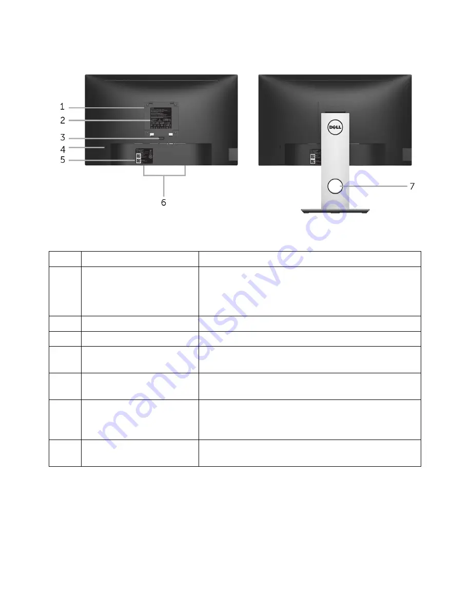
Back view with monitor stand

Description

Use

1

VESA mounting holes 
(100 mm x 100 mm - 
behind attached VESA 
Cover)

Wall mount monitor using VESA-compatible wall 
mount kit (100 mm x 100 mm).

2

Regulatory label

Lists the regulatory approvals.

3

Stand release button

Releases stand from monitor.

4

Security lock slot

Secures monitor with security lock (security lock 
not included). 

5

Barcode, serial number, 
and Service Tag label

Refer to this label if you need to contact Dell for 
technical support.

6

Dell Soundbar mounting 
slots

Attaches the optional Dell Soundbar.

NOTE: 

Please remove the plastic strip covering the 

mounting slots before affixing the Dell Soundbar.

7

Cable-management slot

Use to organize cables by placing them through 
the slot.

About Your Monitor    |   

9

Back View

Label

Summary of Contents for P2217H

Page 1: ...Dell P2217H P2317H P2317HWH P2417H P2717H Monitor User s Guide Model P2217H P2317H P2317HWH P2417H P2717H Regulatory model P2217Hb P2217Hc P2317Hb P2317Ht P2317HWHb P2417Hb P2417Hc P2717Ht ...

Page 2: ... WARNING indicates a potential for property damage personal injury or death ____________________ Copyright 2016 Dell Inc All rights reserved This product is protected by U S and international copyright and intellectual property laws Dell and the Dell logo are trademarks of Dell Inc in the United States and or other jurisdictions All other marks and names mentioned herein may be trademarks of their...

Page 3: ...l Serial Bus USB Interface 24 LCD Monitor Quality and Pixel Policy 26 Maintenance Guidelines 26 Setting Up the Monitor 27 Attaching the Stand 27 Connecting Your Monitor 29 Organizing Your Cables 31 Removing the Monitor Stand 31 Wall Mounting Optional 32 Operating the Monitor 33 Power On the Monitor 33 Using the Front Panel Controls 33 Using the On Screen Display OSD Menu 35 ...

Page 4: ...e Monitor 52 Adjusting the Rotation Display Settings of Your System 53 Troubleshooting 54 Self Test 54 Built in Diagnostics 55 Common Problems 56 Product Specific Problems 58 Universal Serial Bus USB Specific Problems 59 Appendix 60 FCC Notices U S Only and Other Regulatory Information 60 Contact Dell 60 ...

Page 5: ...ived all the components and Contact Dell if something is missing Monitor Stand Riser Stand Base NOTE Some items may be optional and may not ship with your monitor Some features or media may not be available in certain countries NOTE To set up with any other stand please refer to the respective stand setup guide for setup instructions ...

Page 6: ...ries by Countries VGA Cable DP Cable USB 3 0 Upstream Cable Enables the USB Ports on the Monitor Drivers and Documentation Media Quick Setup Guide Safety Environmental and Regulatory Information 6 About Your Monitor ...

Page 7: ... viewable area measured diagonally Resolution Up to 1920 x 1080 through VGA DisplayPort and HDMI with full screen support or lower resolutions Color gamut of 72 NTSC Tilt swivel height and rotate adjustment capabilities Removable stand and Video Electronics Standards Association VESA 100 mm mounting holes for flexible mounting solutions Digital connectivity with DisplayPort and HDMI Equipped with ...

Page 8: ...bout Your Monitor Identifying Parts and Controls Front View Front panel controls Description 1 Function buttons For more information see Operating the Monitor 2 Power On Off button with LED indicator Label ...

Page 9: ...r 4 Security lock slot Secures monitor with security lock security lock not included 5 Barcode serial number and Service Tag label Refer to this label if you need to contact Dell for technical support 6 Dell Soundbar mounting slots Attaches the optional Dell Soundbar NOTE Please remove the plastic strip covering the mounting slots before affixing the Dell Soundbar 7 Cable management slot Use to or...

Page 10: ...SB downstream port Connect your USB device NOTE To use this port you must connect the USB cable shipped with your monitor to the USB upstream port on the monitor and to your computer 10 About Your Monitor Side View Label ...

Page 11: ... monitor using a M3 x 6 mm screw screw not included 5 VGA connector Connect your computer with VGA cable 6 USB upstream port Connect the USB cable shipped with your monitor to this port and your computer to enable the USB ports on your monitor 7 USB downstream port Connect USB device NOTE To use this port you must connect the USB cable shipped with your monitor to the USB upstream port on the moni...

Page 12: ...2 96 Viewing angle 178 vertical typical 178 horizontal typical Brightness 250 cd m typical Contrast ratio 1000 to 1 typical 4 Million 1 Dynamic Display screen coating Anti Glare with 3H hardness Backlight White LED edgelight system Response time typical 6 ms gray to gray Color depth 16 7 million colors Color gamut 82 NTSC CIE1976 Built in devices USB 3 0 super speed hub with 1 x USB 3 0 upstream p...

Page 13: ...46 27 mm2 242 18 inch2 685 80 mm 27 inches 597 92 mm 23 54 inches 336 30 mm 13 24 inches 201073 77 mm2 311 65 inch2 Pixel pitch 0 275 mm x 0 275 mm 0 311 mm x 0 311 mm Pixel per inch PPI 93 82 Viewing angle 178 vertical typical 178 horizontal typical Brightness 250 cd m typical 300 cd m typical Contrast ratio 1000 to 1 typical 4 Million 1 Dynamic Display screen coating Anti Glare with 3H hardness ...

Page 14: ...80i 480p 576i 576p 720p 1080i 1080p Connectivity 1 x DP 1 2 1 x HDMI 1 4 1 x VGA 1 x USB 3 0 port Upstream 2 x USB 3 0 port Side 2 x USB 2 0 port Bottom Border width edge of monitor to active area 11 4 mm Top Left Right 18 1 mm Bottom 11 6 mm Top Left Right 18 2 mm Bottom Adjustability Height adjustable stand Tilt Swivel Pivot 130 mm 5 to 21 45 to 45 90 clockwise Dell Display Manager Compatibility...

Page 15: ...t impedance per differential pair AC input voltage frequency current 100 VAC to 240 VAC 50 Hz or 60 Hz 3 Hz 1 5 A typical Inrush current 120 V 30 A Max at 0 C cold start 220 V 60 A Max at 0 C cold start VESA 640 x 480 31 5 60 0 25 2 VESA 640 x 480 37 5 75 0 31 5 IBM 720 x 400 31 5 70 0 28 3 VESA 800 x 600 37 9 60 0 40 0 VESA 800 x 600 46 9 75 0 49 5 VESA 1024 x 768 48 4 60 0 65 0 VESA 1024 x 768 6...

Page 16: ...3 mm 1 98 inches 50 3 mm 1 98 inches Height extended 400 8 mm 15 78 inches 400 8 mm 15 78 inches Height compressed 354 4 mm 13 95 inches 354 4 mm 13 95 inches Width 242 6 mm 9 55 inches 242 6 mm 9 55 inches Depth 180 0 mm 7 09 inches 180 0 mm 7 09 inches Weight with packaging 6 86 kg 15 09 lb 7 34 kg 16 18 lb Weight with stand assembly and cables 5 37 kg 11 81 lb 5 59 kg 12 32 lb Weight without st...

Page 17: ...inches Height extended 400 8 mm 15 78 inches 433 4 mm 17 06 inches Height compressed 354 4 mm 13 95 inches 387 2 mm 15 24 inches Width 242 6 mm 9 55 inches 292 4 mm 11 51 inches Depth 180 0 mm 7 09 inches 200 3 mm 7 89 inches Weight with packaging 7 63 kg 16 78 lb 9 76 kg 21 52 lb Weight with stand assembly and cables 5 90 kg 12 98 lb 7 44 kg 16 40 lb Weight without stand assembly For wall mount o...

Page 18: ...imum 126 24 BTU hour maximum 58 01 BTU hour typical 129 66 BTU hour maximum 61 42 BTU hour typical 133 07 BTU hour maximum 64 83 BTU hour typical 187 66 BTU hour maximum 78 48 BTU hour typical 18 About Your Monitor Environmental Characteristics Power Management Modes If you have VESA s DPM compliance display card or software installed in your PC the monitor can automatically reduce its power consu...

Page 19: ...ertical Sync Video Power Indicator Power Consumption Normal operation Active Active Active White 38 W maximum 18 W typical Active off mode Inactive Inactive Blanked White blinking Less than 0 3 W Switch off Off Less than 0 3 W Energy Star Power Consumption Pon 14 8 W ETEC 46 7 kWh VESA Modes Horizontal Sync Vertical Sync Video Power Indicator Power Consumption Normal operation Active Active Active...

Page 20: ...umption with max luminance and USB active This document is informational only and reflects laboratory performance Your product may perform differently depending on the software components and peripherals you ordered and shall have no obligation to update such information Accordingly the customer should not rely upon this information in making decisions about electrical tolerances or otherwise No w...

Page 21: ...ected Signal Cable 1 Video Red 2 Video Green 3 Video Blue 4 GND 5 Self test 6 GND R 7 GND G 8 GND B 9 Computer 5 V 3 3 V 10 GND sync 11 GND 12 DDC data 13 H sync 14 V sync 15 DDC clock About Your Monitor 21 Pin Assignments VGA Connector ...

Page 22: ... Connected Signal Cable ML0 p GND ML0 n ML1 p GND ML1 n ML2 p GND ML2 n ML3 p GND ML3 n GND GND AUX p GND AUX n GND Re PWR 3 3 V DP_PWR 22 About Your Monitor DisplayPort Connector 1 2 3 4 5 6 7 8 9 10 11 12 13 14 15 16 17 18 19 20 ...

Page 23: ...MI Connector Plug and Play Capability You can install the monitor in any Plug and Play compatible system The monitor automatically provides the computer system with its Extended Display Identification Data EDID using Display Data Channel DDC protocols so that the system can configure itself and optimize the monitor settings Most monitor installations are automatic you can select different settings...

Page 24: ...gh speed 480 Mbps 4 5 W Max each port Full speed 12 Mbps 4 5 W Max each port Transfer Speed Data Rate Power Consumption High speed 480 Mbps 2 5 W Max each port Full speed 12 Mbps 2 5 W Max each port Low speed 1 5 Mbps 2 5 W Max each port NOTE This monitor is Super Speed USB 3 0 and High Speed USB 2 0 compatible USB 3 0 Upstream Connector Pin Number 9 pin Side of the Connector VCC D D GND SSTX SSTX...

Page 25: ... Your Monitor 25 USB 3 0 Downstream Connector USB 2 0 Downstream Connector Pin Number 4 pin Side of the Connector 1 VCC 2 DMD 3 DPD 4 GND USB Ports 1 x USB 3 0 upstream bottom 2 x USB 2 0 downstream bottom 2 x USB 3 0 downstream side NOTE USB 3 0 functionality requires a USB 3 0 capable computer 1 ...

Page 26: ... cleaning the monitor unplug the monitor power cable from the electrical outlet For best practices follow the instructions in the list below while unpacking cleaning or handling your monitor To clean your anti static screen lightly dampen a soft clean cloth with water If possible use a special screen cleaning tissue or solution suitable for the anti static coating Do not use benzene thinner ammoni...

Page 27: ...d is bought please refer to the respective stand setup guide for the set up instructions To attach the monitor stand 1 Follow the instructions on the flaps of carton to remove the stand from the top cushion that secures it 2 Insert the stand base blocks fully into the stand slot 3 Lift the screw handle and turn the screw clockwise 4 After fully tightening the screw fold the screw handle flat withi...

Page 28: ...ssembly 6 Attach the stand assembly to the monitor a Fit the two tabs on the upper part of the stand to the groove on the back of the monitor b Press the stand down till it snaps into place 7 Place the monitor upright NOTE Lift the monitor carefully to prevent it from slipping or falling ...

Page 29: ... cables through the cable management slot before connecting them NOTE Do not connect all cables to the computer at the same time To connect your monitor to the computer 1 Turn Off your computer and disconnect the power cable 2 Connect the VGA DP or HDMI cable from your monitor to the computer Connecting the VGA cable Connecting the DisplayPort DP to DP cable ...

Page 30: ... monitor setup 1 Connect the upstream USB 3 0 port cable supplied to an appropriate USB 3 0 port on your computer See Bottom View for details 2 Connect the USB 3 0 peripherals to the downstream USB 3 0 ports on the monitor 3 Plug the power cables for your computer and monitor into a nearby outlet 4 Turn On the monitor and the computer If your monitor displays an image installation is complete If i...

Page 31: ...o prevent scratches on the LCD screen while removing the stand ensure that the monitor is placed on a soft clean surface NOTE This is applicable for a monitor with a stand When any other stand is bought please refer to the respective stand setup guide for the set up instructions To remove the stand 1 Place the monitor on a soft cloth or cushion 2 Press and hold the stand release button 3 Lift the ...

Page 32: ... the stand 3 Use a Phillips crosshead screwdriver to remove the four screws securing the plastic cover 4 Attach the mounting bracket from the wall mounting kit to the monitor 5 Mount the monitor on the wall by following the instructions that comes with the wall mounting kit NOTE For use only with UL listed wall mount bracket with minimum weight load bearing capacity of 2 81 kg P2217H 3 06 kg P2317...

Page 33: ... front of the monitor to adjust the characteristics of the image being displayed As you use these buttons to adjust the controls an OSD shows the numeric values of the characteristics as they change The following table describes the front panel buttons Front Panel Button Description 1 Shortcut key Preset Modes Use this button to choose from a list of preset color modes ...

Page 34: ...e the Back button to go back to the previous menu 2 Shortcut key Input Source Use this button to choose from a list of video signals that may be connected to your monitor 3 Menu Use the MENU button to launch the On Screen Display OSD and select the OSD Menu See Accessing the Menu System 4 Exit Use this button to go back to the main menu or exit the OSD main menu 5 Power with power light indicator ...

Page 35: ...n either proceed to another menu or exit the OSD menu the monitor automatically saves those changes The changes are also saved if you change the settings and then wait for the OSD menu to disappear 1 Press the button to launch the OSD menu and display the main menu Main Menu for analog VGA input Main Menu for digital HDMI input ...

Page 36: ...n to another the option name is highlighted See the following table for a complete list of all the options available for the monitor 3 Press the button once to activate the highlighted option 4 Press the and buttons to select the desired parameter 5 Press to enter the slide bar and then use the and buttons according to the indicators on the menu to make your changes 6 Select the button to return t...

Page 37: ...the button to decrease the brightness min 0 max 100 NOTE Manual adjustment of Brightness is disabled when Dynamic Contrast is switched On Contrast Adjust the Brightness first and then adjust the Contrast only if further adjustment is necessary Press the button to increase the contrast and press the button to decrease the contrast min 0 max 100 The Contrast function adjusts the degree of difference...

Page 38: ...r setup Auto Adjust allows the monitor to self adjust to the incoming video signal After using Auto Adjust you can further tune your monitor by using the Pixel Clock Coarse and Phase Fine controls under Display settings NOTE In most cases Auto Adjust produces the best image for your configuration NOTE Auto Adjust option is only available when you are using the analog VGA connector ...

Page 39: ... input source DP Select the DP input when you are using the DisplayPort DP connector Press to select the DisplayPort input source HDMI Select the HDMI input when you are using the HDMI connector Press to select the HDMI input source Auto Select Turning on the function allows you to scan for available input sources Reset Input Source Reset your monitor input settings to the factory settings Color U...

Page 40: ...wing more comfortable for your eyes Multimedia Loads color settings ideal for multimedia applications Movie Loads color settings ideal for movies Game Loads color settings ideal for most gaming applications Warm Increases the color temperature The screen appears warmer with a red yellow tint Cool Decreases the color temperature The screen appears cooler with a blue tint Custom Color Allows you to ...

Page 41: ...ust the hue from 0 to 100 Use to increase the green shade of the video image Use to increase the purple shade of the video image NOTE Hue adjustment is available only when you select Movie or Game preset mode Saturation This feature can adjust the color saturation of the video image Use or to adjust the saturation from 0 to 100 Use to increase the colorful appearance of the video image Use to incr...

Page 42: ...d Pixel Clock adjustments allow you to adjust your monitor to your preference Use or to adjust for best image quality Phase If satisfactory results are not obtained using the Phase adjustment use the Pixel Clock coarse adjustment and then use Phase fine again NOTE Pixel Clock and Phase adjustments are only available for VGA input Dynamic Contrast Allows you to increase the level of contrast to pro...

Page 43: ...nergy USB Allows you to enable or disable USB function during monitor standby mode NOTE USB ON OFF under standby mode is only available when the USB upstream cable is unplugged This option will be greyed out when the USB upstream cable plugs in Reset Energy Select this option to restore default Energy settings ...

Page 44: ...this option to change the menu transparency by pressing the and buttons min 0 max 100 Timer Allows you to set the time for which the OSD remains active after you press a button on the monitor Use or to adjust the slider in 1 second increments from 5 to 60 seconds Lock Controls user access to adjustments When Lock is selected no user adjustments are allowed All buttons are locked NOTE Unlock functi...

Page 45: ...Operating the Monitor 45 Personalize Users can choose a feature from Preset Modes Brightness Contrast Auto Adjust Input Source Aspect Ratio or Rotation and set it as a shortcut key ...

Page 46: ...g and so on DDC CI DDC CI Display Data Channel Command Interface allows your monitor parameters brightness color balance and etc to be adjustable via the software on your computer You can disable this feature by selecting Disable Enable this feature for best user experience and optimum performance of your monitor ...

Page 47: ...hese preset modes Game or Movie manual brightness adjustment is disabled LCD Conditioning Helps reduce minor cases of image retention Depending on the degree of image retention the program may take some time to run You can enable this feature by selecting Enable Reset Others Reset all settings under the Others menu to the factory preset values Factory Reset Reset all settings to the factory preset...

Page 48: ...ency ranges addressable by this monitor Recommended mode is 1920 x 1080 You will see the following message before the DDC CI function is disabled When the monitor goes into power save mode the following message appears Activate the computer and wake up the monitor to gain access to the OSD If you press any button other than the power button the following message will appear depending on the select...

Page 49: ...perating the Monitor 49 If either VGA HDMI or DP input is selected and the corresponding cable is not connected a floating dialog box as shown below appears or or See Troubleshooting for more information ...

Page 50: ...tings 2 Click Advanced display settings 3 Click the dropdown list of Resolution and select 1920 x 1080 4 Click Apply If you do not see 1920 x 1080 as an option you may need to update your graphics driver Depending on your computer complete one of the following procedures If you have a Dell desktop or portable computer Go to http www dell com support enter your service tag and download the latest d...

Page 51: ...pective stand setup guide for set up instructions Tilt Swivel With the stand attached to the monitor you can tilt and swivel the monitor for the most comfortable viewing angle NOTE The stand is detached when the monitor is shipped from the factory Vertical Extension NOTE The stand extends vertically up to 130 mm The figure below illustrates how to extend the stand vertically ...

Page 52: ...the Display Rotation function Landscape versus Portrait view with your Dell computer you require an updated graphics driver that is not included with this monitor To download the graphics driver go to www dell com support and see the Download section for Video Drivers for latest driver updates NOTE When in the Portrait View Mode you may experience performance degradation in graphic intensive appli...

Page 53: ...y Settings 1 Right click on the desktop and click Properties 2 Select the Settings tab and click Advanced 3 If you have an ATI graphics card select the Rotation tab and set the preferred rotation 4 If you have an nVidia graphics card click the nVidia tab in the left hand column select NVRotate and then select the preferred rotation 5 If you have an Intel graphics card select the Intel graphics tab...

Page 54: ...r screen remains dark run the monitor self test by performing the following steps 1 Turn off both your computer and the monitor 2 Unplug the video cable from the back of the computer 3 Turn on the monitor The floating dialog box should appear on screen against a black background if the monitor cannot sense a video signal and is working correctly While in self test mode the power LED remains white ...

Page 55: ...ty you are experiencing is an inherent problem with your monitor or with your computer and video card NOTE You can run the built in diagnostics only when the video cable is unplugged and the monitor is in self test mode To run the built in diagnostics 1 Ensure that the screen is clean no dust particles on the surface of the screen 2 Unplug the video cable s from the back of the computer or monitor...

Page 56: ... Input Source menu No Video Power LED on No picture or no brightness Increase brightness contrast controls via OSD Perform monitor self test feature check Check for bent or broken pins in the video cable connector Run the built in diagnostics Ensure that the correct input source is selected in the Input Source menu Poor Focus Picture is fuzzy blurry or ghosting Perform Auto Adjust via OSD Adjust t...

Page 57: ...ns in the video cable connector Run the built in diagnostics NOTE When using HDMI DisplayPort input the Pixel Clock and Phase adjustments are not available Synchronization Problems Screen is scrambled or appears torn Reset the monitor to factory settings Perform Auto Adjust via OSD Adjust the Phase and Pixel Clock controls via OSD Perform monitor self test feature check to determine if the scrambl...

Page 58: ...ing any key on the keyboard Check whether the signal cable is plugged in properly Re plug the signal cable if necessary Reset the computer or video player The picture does not fill the entire screen The picture cannot fill the height or width of the screen Due to different video formats aspect ratio of DVDs the monitor may display in full screen Run the built in diagnostics NOTE When choosing HDMI...

Page 59: ...mputer is USB 3 0 capable Some computers have USB 3 0 USB 2 0 and USB 1 1 ports Ensure that the correct USB port is used Reconnect the upstream cable to your computer Reconnect the USB peripherals downstream connector Reboot the computer Wireless USB peripherals stop working when a USB 3 0 device is plugged in Wireless USB peripherals responding slowly or only working as the distancebetween itself...

Page 60: ...gulatory information see the regulatory compliance website located at www dell com regulatory_compliance Contact Dell For customers in the United States call 800 WWW DELL 800 999 3355 NOTE If you do not have an active Internet connection you can find contact information on your purchase invoice packing slip bill or Dell product catalog Dell provides several online and telephone based support and s...

Reviews: