background image

Drive Hardware Removal (Mini Tower Chassis): OptiPlex GX1p 

Drive Hardware

 | 

3.5-Inch Diskette-Drive Removal

 | 

5.25-Inch Drive Assembly Removal

 | 

Hard-Disk Drive Bracket Removal

 | 

Hard-Disk Drive Assembly Removal


Drive Hardware 


3.5-Inch Diskette-Drive Removal  


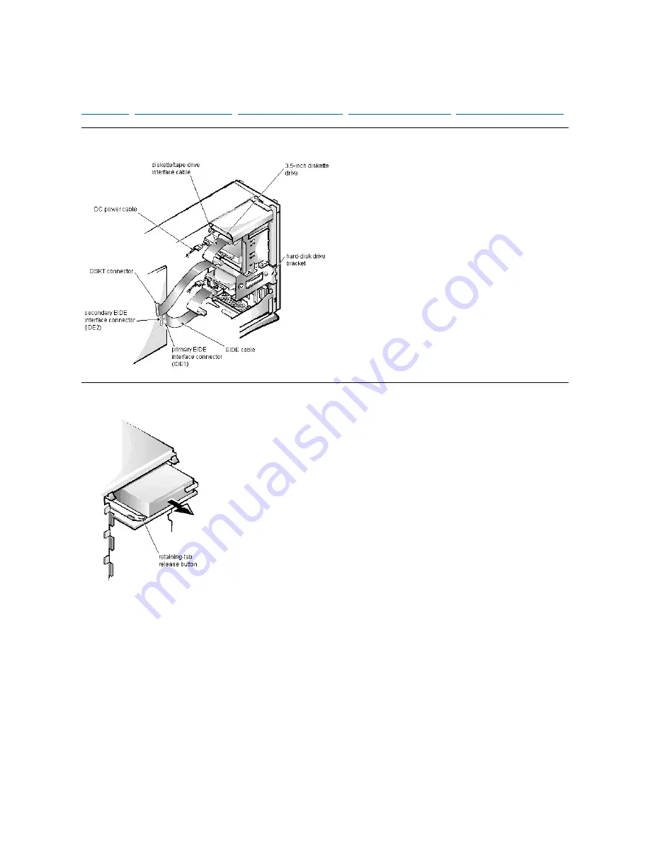
To remove a 3.5-inch diskette drive assembly, follow these steps:  

1. Disconnect the DC power cable and the interface cable from the back of the 3.5-inch diskette drive.  
2. Press the retaining-tab release button, and pull the drive assembly forward to remove it.  
3. Remove the drive-mounting screw from the left side of the drive, and remove the drive from the bracket.  

Summary of Contents for OptiPlex GX1p

Page 1: ...Dell OptiPlex GX1p Specifications Jumpers Controls and Indicators Tech Notes Graphics Documentation Initial release 21 Aug 1998 Last revised 5 Apr 2000 ...

Page 2: ...ated ATAPI driver diskette in drive A 4 Click the Start button 5 Click Run type a setup bat in the Run window and then click OK A black screen will quickly appear and disappear which indicates that the driver file has been loaded Setup automatically saves the existing atapi sys driver as atapi 000 and loads the new driver into the system32 drivers subdirectory in the Windows NT directory 6 Remove ...

Page 3: ...lty or improperly seated DIMM or address line failure in the first 64 KB of RAM System riser cards may cause this error Remove the riser card and retest 2 1 1 through 2 4 4 Bit failure in the first 64 KB of main memory Faulty or improperly seated DIMM 3 1 1 Slave DMA register failure Defective system board 3 1 2 Master DMA register failure Defective system board 3 1 3 Master interrupt mask registe...

Page 4: ...Bus mastering Dell OptiPlex GX1p This system supports PCI bus mastering on all slots ...

Page 5: ...ive access indicator Lights up when the hard disk drive is being accessed Diskette drive access indicator Lights up when the diskette drive is being accessed Power button Turns computer on and off Power indicator Lights up when the computer is on Reset button Initiates a hardware reset To avoid possible data or file structure corruption use the reset button only when the system cannot be rebooted ...

Page 6: ...ent Interface DMI support to display detailed information about the hardware and software configuration of the system The Dell Inspector is in the Dell Accessories program group Dell Inspector online help Production Note This link is to another separate OTI which is not part of this review ...

Page 7: ...O controller to initiate DMA cycle for attached diskette drive DREQ3 Available DREQ4 Bus controller chip to activate second DMA controller DREQ5 Available DREQ6 Available DREQ7 Available NOTE The onboard sound controller NIC and video controllers are assigned available DMA channels automatically during system start up ...

Page 8: ...ll OpenManage Client 4 2 on all systems that have Dell installed Microsoft Windows operating systems Dell OpenManage Client 4 2 uses DMI support to display detailed information about the hardware and software configuration of the system For information about Dell OpenManage Client 4 2 refer to the Dell OpenManage Client 4 2 online help located on your system in the Dell OpenManage Client 4 2 progr...

Page 9: ...ide pdf Dell OptiPlex GX1 GX1p Managed PC and OptiPlex NX1 Net PC Systems Service Manual pdf To view a PDF file launch Adobe Acrobat Reader Click File Open and select the PDF file NOTE Help files require winhelp exe which is part of the Microsoft Windows operating system located in the windows directory To view help files online you may need to configure winhelp exe to work with your browser as a ...

Page 10: ......

Page 11: ...Drivers and Utilities OptiPlex GX1p See Using Drivers and Utilities in the online System User s Guide ...

Page 12: ...z besoin d Acrobat Reader que vous pouvez décharger du site web d Adobe Pour afficher les fichiers pdf en ligne après le chargement et l installation d Acrobat Reader vou devrez peut être con figurer Acrobat Reader pour qu il fonctionne avec votre navigateur comme application d aide ou module enfichable Reportez vous aux informations d aide de votre navigateur pour plus de précisions Les fichiers ...

Page 13: ...icators Internal View of the Midsize Computer Internal View of the Mini Tower Computer Riser Board for the Midsize Computer Riser Board for the Mini Tower Computer I O Ports and Connectors System Setup Additional graphics can be found in Removing and Replacing Parts ...

Page 14: ...Internal View of the Low Profile Computer Dell OptiPlex GX1p ...

Page 15: ...Internal View of the Midsize Computer Dell OptiPlex GX1p ...

Page 16: ...Internal View of the Mini Tower Computer Dell OptiPlex GX1p ...

Page 17: ...System Board Dell OptiPlex GX1p ...

Page 18: ...ers 0044 005F Reserved 0060 006F Keyboard controller 0070 0071 RTC and NMI enable 0080 008F DMA page registers 00A0 00BF Interrupt controller 2 00C0 00DF DMA controller 2 00F0 Coprocessor busy clear 00F1 Coprocessor busy reset 00F2 00FF Available 278 27F LPT2 2E8 2EF COM4 2F8 2FF COM2 378 37F LPT1 3E8 3EF COM3 3F8 3FF COM1 ...

Page 19: ...I O Ports and Connectors Dell OptiPlex GX1p ...

Page 20: ...le IRQ line IRQ Line System Resource IRQ0 System timer IRQ1 Keyboard port IRQ2 Enables IRQ8 through IRQ15 IRQ31 Available IRQ4 Serial port IRQ5 Audio controller IRQ6 Diskette tape drive controller IRQ7 Parallel port IRQ8 RTC IRQ9 Available except in ACP enabled configurations while running Windows 98 IRQ10 Available IRQ112 NIC default PCI IRQ IRQ12 Mouse port IRQ13 Math coprocessor IRQ14 Primary E...

Page 21: ...essor s internal speed is 450 MHz see footnote 1 400MHZ1 Jumpered when the microprocessor s internal speed is 400 MHz see footnote 1 350MHZ Not supported on the GX1p 333MHZ Not supported on the GX1p 300MHZ Not supported on the GX1p 266MHZ2 Jumpered for 266 MHz see footnote 2 BUS66M default External system clock speed is 66 MHz when jumpered External system clock speed operates at 100 MHz when not ...

Page 22: ...s or sockets if you attempt to insert the wrong DIMM type in the computer Total DIMM_A DIMM_B DIMM_C 128 MB 64 MB 64 MB 128 MB 128 MB 192 MB 128 MB 64 MB 256 MB 128 MB 128 MB 256 MB 256 MB 320 MB 128 MB 128 MB 64 MB 384 MB 128 MB 128 MB 128 MB 512 MB 256 MB 256 MB 768 MB 256 MB 256 MB 256 MB Memory Range Address Range Size Description 1024 131 072 KB 100000 8000000h 127 MB Extended memory 960 1023...

Page 23: ...drive interface cable or loose power cable Diskette read failure Failure occurred while system attempted to read diskette Faulty diskette faulty or improperly connected diskette tape drive interface cable or loose power cable Diskette subsystem reset failed System could not successfully issue reset command to diskette controller Faulty diskette tape drive controller defective system board Diskette...

Page 24: ...te tape drive subsystem or hard disk drive subsystem Not a boot diskette No operating system on diskette No operating system on diskette Plug and Play Configuration Error System encountered problem in trying to configure one or more expansion cards System resource conflict Read fault Requested sector not found MS DOS cannot read from diskette or hard disk drive System could not find particular sec...

Page 25: ... or more DIMMs improperly seated Indicates a fatal error keyboard mouse controller chip defective system board Write fault Write fault on selected drive MS DOS cannot write to diskette or hard disk drive Faulty diskette or hard disk drive ...

Page 26: ... the system board The NIC connector on the computer s back panel has the following indicators l A yellow activity indicator that flashes when the system is transmitting or receiving network data A high volume of network traffic may make this indicator appear to be in a steady on state l A green link integrity indicator that lights up when there is a good connection between the network and the NIC ...

Page 27: ...rd Disk Drive Options I O Map POST Beep Codes PCI to PCI Bridging NIC System Error Messages IRQ Assignments DMA Channel Assignments System Setup Drivers and Utilities Removing and Replacing Parts Wakeup On LAN Bus mastering Updated ATAPI DMI Support Dell OpenManage Client ...

Page 28: ...PCI to PCI Bridging OptiPlex GX1p PCI to PCI bridging is supported in this system ...

Page 29: ...surges of up to 11 0 A to support disk start up operations 3 VFP volts flea power sometimes called standby power DC Power Cables DC Power Distribution Midsize Chassis NOTE Each power supply produces DC voltages only under its loaded condition Therefore when you measure these voltages the DC power connectors must be connected to their corresponding power input connectors on the system board or driv...

Page 30: ...DC Power Distribution Mini Tower Chassis ...

Page 31: ...puter 4 Wear a wrist grounding strap and clip it to an unpainted metal surface such as the padlock ring on the back of the chassis If a wrist grounding strap is not available touch an unpainted metal surface on the back of the computer to discharge any static charge from your body CAUTION The computer s power supply continues to supply flea power to the system board whenever the computer is turned...

Page 32: ......

Page 33: ...and Play ISA expansion cards and PCI expansion cards the next time the computer is rebooted Configuring Expansion Cards in the online System User s Guide describes the ICU and provides instructions for using it to configure the computer Low Profile Chassis Riser Board ISA1 and PCI2 share the same card slot opening The low profile computers have a passive riser board with no PCI to PCI bridge Midsi...

Page 34: ...s an active riser board with a PCI to PCI bridge ISA1 shares its card slot opening with PCI4 and ISA2 shares its card slot opening with PCI5 Mini Tower Chassis Riser Board ISA1 shares its card slot opening with PCI4 and ISA2 shares its card slot opening with PCI5 The riser board is active incorporating PCI to PCI bridging ...

Page 35: ...Riser Board for the Low Profile Computer Dell OptiPlex GX1p ...

Page 36: ...Riser Board for the Midsize Computer Option 1 Dell OptiPlex GX1p ...

Page 37: ...Riser Board for the Mini Tower Computer Dell OptiPlex GX1p ...

Page 38: ...Riser Board for the Midsize Computer Option 2 Dell OptiPlex GX1p ...

Page 39: ...ecting the NIC to the riser cable and an LED If the LED is on the riser board is receiving power if it is off the riser board is not receiving power Mini Tower Chassis Riser Board ISA1 shares its card slot opening with PCI4 and ISA2 shares its card slot opening with PCI5 The riser board is active incorporating PCI to PCI bridging The riser board includes the P1 connector for connecting the NIC to ...

Page 40: ...installed 3 Press in on the 2 securing buttons until the cover is free to swing up 4 Raise the back of the cover and pivot it toward the front of the computer 5 Lift the cover off of the hooks at the front of the chassis Three plastic hooks on the inside front part of the cover secure it to the chassis Before you reinstall the cover fold all cables out of the way so that they do not interfere with...

Page 41: ...ore you slide the system board back to lock it in position push down near each slot to engage the grounding clip onto its corresponding tab Push evenly on both sides of the system board as you slide it into position do not twist the system board NOTES If you are replacing the system board remove all DIMMs the video memory upgrade module if present the single edge contact SEC cartridge heat sink as...

Page 42: ...wer supply 2 Locate the DIMM that you wish to remove 3 Push outward on the DIMM socket s securing clips until the DIMM is released from its socket 4 Lift the DIMM away from the socket DIMM Installation 1 Install the replacement DIMM by pressing the DIMM fully into the socket while closing the securing clips to lock the DIMM into the socket 2 Replace all assemblies and cables previously removed ...

Page 43: ...ion card cage 5 Replace the computer cover and reconnect the AC power cable to the AC outlet Press the power button on the computer to reboot the system 6 Enter the System Setup program and confirm that 8 MB is shown for Video Memory If the total memory is listed incorrectly repeat steps 1 through 6 to reseat the video memory upgrade module and verify that the computer acknowledges the module 7 Ru...

Page 44: ... press inward on the SEC cartridge release latches located directly on top of the SEC cartridge adjacent to the heat sink assembly until the latches click 6 Lift the SEC cartridge heat sink assembly out of its guide bracket assembly connector on the system board WARNING The SEC cartridge heat sink assembly can get extremely hot during system operations Be sure that the assembly has had sufficient ...

Page 45: ...r cover reconnect all cabling and reboot the system 7 Enter the System Setup program and configure the system using the information you recorded in step 1 8 Turn off the computer wait 10 or more minutes and then reenter the System Setup program to ensure that the date and time are still correct indicating that the system battery is functioning correctly CAUTION If you pry out the battery with a bl...

Page 46: ... with the back of the cover facing you 2 To remove the 3 5 inch diskette drive eject button pull gently on the plastic part of the button until it comes free 3 To remove the power button or the reset button use a small screwdriver and push in on the 2 or 3 plastic clips that hold the button to the computer cover When these clips are released the button comes free from the front panel of the cover ...

Page 47: ...e with the front of the cover facing you 2 From the front of the cover use your thumbs to push inward on the insert until it slides off the 2 posts To replace a 5 25 inch front panel insert position the 2 ring tabs over the posts on the inside of the bay opening and then press the ring tabs over the posts If necessary use a 1 4 inch nut driver to help push on the ring tabs ...

Page 48: ...he control panel cable from the PANEL connector on the system board 2 From the inside of the chassis remove the mounting screw holding the control panel to the chassis 3 Remove the control panel from the chassis When you reinstall the control panel be sure to put the right side of the control panel behind the mounting tab ...

Page 49: ... and the interface cable from the back of the diskette drive 2 Press the 2 3 5 inch diskette drive assembly latches to the left to release the assembly 3 Rotate the left side of the assembly up and lift the assembly out of the chassis 4 Remove the 2 drive mounting screws from the left side of the drive and remove the drive from the bracket When you replace the 3 5 inch diskette drive be sure that ...

Page 50: ... the order stamped on the bottom of the bracket Check the alignment of the computer cover around the 5 25 inch drive bezel Adjust the drive forward or backward on the bracket to align it Hard Disk Drive Assembly Removal To remove the hard disk drive follow these steps 1 Disconnect the DC power cable and the interface cable from the back of the drive 2 Loosen the captive screw that secures the hard...

Page 51: ... the chassis 4 Slide the system power supply forward until it stops then lift it from the chassis When you replace the system power supply place it down inside the chassis and against the right side of the chassis Then slide it toward the back of the chassis and hook the tabs into the right side of the power supply WARNING The voltage selection switch located on the back of the power supply assemb...

Page 52: ... against the chassis to ensure that the lever engages the notch in the chassis when the lever is depressed If reinstalling an ISA expansion card into the expansion card cage be sure to slip the end of the ISA expansion card into the plastic ISA expansion card end support The ISA expansion card end support should not be removed however if it is accidentally removed reinstall it by first inserting i...

Page 53: ...card follow these steps 1 Disconnect any external cables from the expansion card being removed 2 Remove the expansion card cage 3 Remove the retaining screw from the card mounting bracket 4 Grasp the expansion card by its corners and carefully remove it from the expansion card connector ...

Page 54: ...nd remove all expansion cards 2 Lay the expansion card cage on a flat work surface with the riser board facing up 3 Remove the 2 riser board mounting screws 4 Lift the riser board away from the expansion card cage When you replace the riser board be sure that the alignment feature on the expansion card cage engages with the alignment slot ...

Page 55: ...Place the right side of the computer on a flat work surface 2 Unscrew the optional stand screw Use your fingers or a wide flat blade screwdriver to unscrew the optional stand screw 3 Pull the stand away from the computer Disengage the 3 orientation nubs that position and help secure the stand to the computer ...

Page 56: ... 1 Remove the expansion card cage and remove all expansion cards 2 On a flat work surface turn the expansion card cage over so that the riser board faces up 3 Remove the riser board mounting screws 4 Slide the riser board down until it stops then lift the riser board away from the expansion card cage ...

Page 57: ...e you slide the system board back to lock it in position push down near each slot to engage the grounding clip onto its corresponding tab Push evenly on both sides of the system board as you slide it into position do not twist the system board NOTES If you are replacing the system board remove all DIMMs the video memory upgrade module if present the single edge contact SEC cartridge heat sink asse...

Page 58: ...released from its socket 4 Lift the DIMM away from the socket DIMM Installation 1 Reinstall the replacement DIMM by pressing the DIMM fully into the socket while closing the securing clips to lock the DIMM into the socket 2 Replace all assemblies and cables previously removed CAUTION Do not use EDO DIMMs in this computer This computer uses SDRAM DIMMs EDO and SDRAM DIMMs have slightly different ga...

Page 59: ...total memory is listed incorrectly repeat steps 1 through 6 to reseat the video memory upgrade module and verify that the computer acknowledges the module 7 Run the system diagnostics Video Test Group to test the new video memory upgrade module CAUTION To avoid possible damage to the video memory upgrade socket and or video memory upgrade module the module is keyed and must be correctly positioned...

Page 60: ...idge release latches located directly on top of the SEC cartridge adjacent to the heat sink assembly until the latches click 6 Lift the SEC cartridge heat sink assembly out of its guide bracket assembly connector on the system board WARNING The SEC cartridge heat sink assembly can get extremely hot during system operations Be sure that the assembly has had sufficient time to cool before touching i...

Page 61: ...ter cover reconnect all cabling and reboot the system 8 Enter the System Setup program and configure the system using the information you recorded in step 1 9 Turn off the computer wait 10 or more minutes and then reenter the System Setup program to ensure that the date and time are still correct indicating that the system battery is functioning correctly CAUTION If you pry out the battery with a ...

Page 62: ...s in on the 2 securing buttons until the cover is free to swing up 3 Raise the back of the cover and pivot it toward the front of the computer 4 Lift the cover off the hooks at the front of the chassis Four plastic hooks on the inside front part of the cover secure it to the chassis Before you replace the cover fold all cables out of the way so that they do not interfere with the cover or with pro...

Page 63: ... the back of the cover facing you 2 To remove the 3 5 inch diskette drive eject button pull gently on the plastic part of the button until it comes free 3 To remove the power button or the reset button use a small screwdriver and push in on the 2 or 3 plastic clips that secure the button to the computer cover When these clips are released the button comes free from the front panel of the cover ...

Page 64: ...th the front of the cover facing you 2 From the front of the cover use your thumbs to push inward on the insert until it slides off the 2 posts To replace a 5 25 inch front panel insert position the 2 ring tabs over the posts on the inside of the bay opening and then press the ring tabs over the posts If necessary use a 1 4 inch nut driver to help push on the ring tabs ...

Page 65: ...rd disk drive bracket 2 Disconnect the control panel cable from the PANEL connector on the system board 3 Remove the mounting screw holding the control panel to the chassis 4 Slide the control panel out of the hooks holding it to the chassis 5 Note the routing of the control panel cable as you remove it from the chassis ...

Page 66: ...DC power cable and the interface cable from the back of the 3 5 inch diskette drive 2 Remove the bracket mounting screw 3 Rotate the left side of the 3 5 inch diskette drive up and lift the drive out of the chassis 4 Remove the 2 drive mounting screws from the left side of the drive and remove the drive from the bracket When you replace the 3 5 inch diskette drive be sure that the 2 hooks on the r...

Page 67: ...ace the 5 25 inch drive align the front of the drive flush with the tab at the front of the mounting plate Insert the 4 screws and tighten them in the order stamped on the bottom of the 5 25 inch drive mounting plate Hard Disk Drive Bracket Removal To remove the hard disk drive bracket follow these steps 1 Disconnect the DC power cable and the interface cable from the back of each hard disk drive ...

Page 68: ...be sure that the opening in the lower back tab is over the alignment tab on the chassis then rotate the front of the bracket down into position Hard Disk Drive Assembly Removal To remove the hard disk drive follow these steps 1 Remove the hard disk drive bracket 2 Remove the 4 screws that attach the hard disk drive to the hard disk drive bracket One hard disk drive attaches to the hard disk drive ...

Page 69: ...RELEASE and rotate it upward until it locks Press the securing tab to release the power supply 3 Remove the power supply mounting screw at the back of the chassis 4 Disconnect the DC power cables from the system board and the drives 5 Facing the left side of the computer move the front end of the system power supply toward you and lift it up to disengage the power supply from the slot in the chass...

Page 70: ...steps 1 Rotate the lever toward the back of the computer until it stops in the upright position 2 Lift the expansion card cage up and away from the computer To replace an expansion card cage keep it flush against the chassis to ensure that the lever engages the notch in the chassis when the lever is depressed ...

Page 71: ...rd follow these steps 1 Disconnect any external cables from the expansion card being removed 2 Remove the expansion card cage 3 Remove the retaining screw from the card mounting bracket 4 Grasp the expansion card by its corners and carefully remove it from the expansion card connector ...

Page 72: ...ock if one is installed 3 Facing the left side of the computer press the release button at the bottom left corner of the front bezel 4 Lift the bottom of the cover allowing it to pivot up toward you 5 Disengage the tabs that secure the cover to the top of the chassis and lift the cover away Before you reinstall the cover fold all cables out of the way so that they do not interfere with the cover o...

Page 73: ...e the expansion card cage and remove all expansion cards 2 Place the expansion card cage on a flat work surface with the riser board facing up 3 Remove the riser board mounting screws 4 Slide the riser board away from the release handle until it stops then lift the riser board away from the expansion card cage ...

Page 74: ...re you slide the system board back to lock it in position push down near each slot to engage the grounding clip onto its corresponding tab Push evenly on both sides of the system board as you slide it into position do not twist the system board NOTES If you are replacing the system board remove all DIMMs the video memory upgrade module if present the single edge contact SEC cartridge heat sink ass...

Page 75: ... released from its socket 4 Lift the DIMM away from the socket DIMM Installation 1 Reinstall the replacement DIMM by pressing the DIMM fully into the socket while closing the securing clips to lock the DIMM into the socket 2 Replace all assemblies and cables previously removed CAUTION Do not use EDO DIMMs in this computer This computer uses SDRAM DIMMs EDO and SDRAM DIMMs have slightly different g...

Page 76: ...reboot the system 6 Enter the System Setup program and confirm that 8 MB is shown for Video Memory If the total memory is listed incorrectly repeat steps 1 through 6 to reseat the video memory upgrade module and verify that the computer acknowledges the module 7 Run the system diagnostics Video Test Group to test the new video memory upgrade module CAUTION To avoid possible damage to the video mem...

Page 77: ...ridge release latches located directly on top of the SEC cartridge adjacent to the heat sink assembly until the latches click 6 Lift the SEC cartridge heat sink assembly out of its guide bracket assembly connector on the system board WARNING The SEC cartridge heat sink assembly can get extremely hot during system operations Be sure that the assembly has had sufficient time to cool before touching ...

Page 78: ...er cover reconnect all cabling and reboot the system 8 Enter the System Setup program and configure the system using the information you recorded in step 1 9 Turn off the computer wait 10 or more minutes and then reenter the System Setup program to ensure that the date and time are still correct indicating that the system battery is functioning correctly CAUTION If you pry out the battery with a b...

Page 79: ... OptiPlex GX1p To remove the front bezel follow these steps 1 Press the tab release marked with the icon 2 Tilt the bezel away from the chassis 3 Disengage the 2 retaining hooks at the bottom of the bezel and pull the bezel away from the chassis ...

Page 80: ...surface with the back of the bezel facing up 2 To remove the 3 5 inch diskette drive eject button pull gently on the plastic part of the button until it comes free 3 To remove the power button or the reset button use a small screwdriver and push in on the 2 or 3 plastic clips that hold the button to the bezel When these clips are released the button comes free from the bezel ...

Page 81: ... inch front panel insert position the 2 ring tabs over the posts on the inside of the bay opening and then press the ring tabs over the posts To remove a 3 5 inch front panel insert follow these steps 1 Hold the bezel with the front facing you 2 Inside the bezel press the eject button mechanism toward the front panel to snap the plastic insert out of its opening To replace the 3 5 inch front panel...

Page 82: ...hard disk drive bracket 2 Disconnect the control panel cable from the PANEL connector on the system board 3 Remove the mounting screw holding the control panel to the chassis 4 Slide the control panel out of the hooks holding it to the chassis Note the routing of the control panel cable as you remove it from the chassis ...

Page 83: ...rive Hardware 3 5 Inch Diskette Drive Removal To remove a 3 5 inch diskette drive assembly follow these steps 1 Disconnect the DC power cable and the interface cable from the back of the 3 5 inch diskette drive 2 Press the retaining tab release button and pull the drive assembly forward to remove it 3 Remove the drive mounting screw from the left side of the drive and remove the drive from the bra...

Page 84: ...r cable and the interface cable from the back of the drive 2 Press in on the 2 retaining tabs 1 on each side of the drive and slide the drive assembly forward to remove it 3 Remove the 4 screws attaching the 5 25 inch drive to the mounting plate and lift the drive out of the mounting plate When you replace the 5 25 inch drive align the front of the drive flush with the tab at the front of the moun...

Page 85: ...it from the computer When you reinstall the hard disk drive bracket insert the bracket s hinge tabs into the chassis slot so that the tabs hook over the slot Then rotate the bracket toward the drive cage and fit the bracket s sliding tab on the drive cage slide rail Hard Disk Drive Assembly Removal To remove the hard disk drive assembly follow these steps 1 Remove the hard disk drive bracket 2 Rem...

Page 86: ...power supply 3 Remove the power supply mounting screw at the back of the chassis 4 Disconnect the DC power cables from the system board and the drives 5 Facing the left side of the computer move the front end of the system power supply toward you and lift it up to disengage the power supply from the slot in the chassis 6 Lift the system power supply from the computer When you reinstall the system ...

Page 87: ... of the computer until it stops in the upright position 2 Slide the expansion card cage out of the computer To replace the expansion card cage align the tabs on the left and right sides of the expansion card cage with the slots on the back and bottom of the chassis With the securing lever in its extended position slide the expansion card cage into place ...

Page 88: ...ion card follow these steps 1 Disconnect any cables from the expansion card being removed 2 Remove the expansion card cage 3 Remove the retaining screw from the card mounting bracket 4 Grasp the expansion card by its corners and carefully remove it from the expansion card connector ...

Page 89: ...was previously removed To clear this message and allow future intrusions to be detected make sure that the computer cover is closed and then enter the System Setup program during the system s POST and press any key to reset the Chassis Intrusion from Detected to Enabled The option can also be set to Disabled to turn off the chassis intrusion feature or Enabled Silent to prevent the alert message f...

Page 90: ...up Dell OptiPlex GX1p For detailed information on System Setup options see Using the System Setup Program in the online System User s Guide NOTE The Chassis Intrusion option has been updated See Chassis Intrusion ...

Page 91: ...System Setup Dell OptiPlex GX1p See Using the System Setup Program in the online System User s Guide ...

Page 92: ... mas rápido NOTAS Los archivos pdf requieren Acrobat Reader el que puede ser descargado de la página web de Adobe Para leer archivos pdf en línea después de descargar e instalar Acrobat Reader usted necesita configurar Acrobat Reader para que trabaje con su browser como una aplicación de ayuda o de tipo plug in Consulte la información en Ayuda asociada con su browser para obtener información adici...

Page 93: ...MA channels 7 Timers 3 Interrupt levels 16 Flash EPROM BIOS 2 Mb BIOS source Dell NIC controller chip onboard 3Com PCI 3C905B TX Wakeup On LAN NIC operating at 10 or 100 Mbps I O controller chip National PC87309 Expansion Bus Bus type PCI 2 1 compliant and ISA PCI expansion card connectors Midsize chassis 5 2 PCI connectors share expansion card slots with ISA connectors Mini tower chassis 5 2 PCI ...

Page 94: ...kette tape or CD ROM drives 1 3 5 inch bay for a diskette drive Internally accessible bays Midsize chassis 2 3 5 inch bays 1 for a 1 inch high hard disk drive and 1 for a 1 6 inch high hard disk drive Mini tower chassis 2 3 5 inch bays 1 for a 1 inch high hard disk drive and 1 for a 1 6 inch high hard disk drive See Hard Disk Drive Options for information on options and restrictions Ports External...

Page 95: ... miniature audio jack amplified Microphone 1 miniature audio jack Video Video type onboard ATI RAGE PRO TURBO graphics Video memory 8 MB SGRAM Supported Resolutions Video Resolution Maximum Color Depth Maximum Refresh Rate 640 x 480 True color 32 bpp 85 Hz 800 x 600 True color 32 bpp 85 Hz 1024 x 768 True color 32 bpp 85 Hz 1280 x 1024 True color 32 bpp 85 Hz 1600 x 1200 65 535 colors 16 bpp 75 Hz...

Page 96: ...0 5 G at 3 to 200 Hz at 1 octave min Maximum shock Operating left side for mini tower orientation and bottom for midsize orientation half sine pulse with a change in velocity of 20 inches sec 50 8 cm sec Storage 27 G faired square wave with a velocity change of 200 inches sec 508 cm sec Altitude Operating 16 to 3048 m 50 to 10 000 ft Storage 16 to 10 600 m 50 to 35 000 ft The maximum operating tem...

Page 97: ...Category B VCCI Notice Japan only Class 1 Class 2 Korean Regulatory Notice Class A Class B NOM 024 Information Mexico only Polish Center for Testing and Certification 1 For the mini tower chassis when networked 2 For the mini tower chassis when in stand alone mode ...

Page 98: ... contain one of the following l 1 or 2 1 inch high EIDE hard disk drives l 1 1 inch high EIDE and 1 1 6 inch high EIDE hard disk drive l 1 1 inch high SCSI hard disk drive l 1 1 6 inch high SCSI hard disk drive NOTE Dell does not support using 2 SCSI hard disk drives in the system because of thermal issues You can use an IDE hard disk drive and a SCSI hard disk drive in the same system but Dell do...

Page 99: ...System Board Dell OptiPlex GX1p The GX1p system board supports a 500 MHz microprocessor ...

Page 100: ...System Boards Dell OptiPlex GX1p First revision system board ...

Page 101: ...System Board Dell OptiPlex GX1 Systems Second revision system board ...

Page 102: ...test ...

Page 103: ...test ...

Page 104: ... microprocessor s chip set for high performance required for 3D video subsystems This architecture also off loads video data from the PCI bus providing greater performance for devices attached to the PCI bus The maximum supported resolution is 1600 x 1200 with 65 535 colors 16 bpp at 75 Hz Other supported resolutions are listed in Specifications The SVGA subsystem has the following major component...

Page 105: ...Wakeup On LAN Dell OptiPlex GX1p The Dell OptiPlex GX1p is available with an integrated Wakeup On LAN capable network option ...

Page 106: ...he wrong memory in a system 3 Update DC Power Distribution Midsize Chassis power htm fig13 gif Giving to GR on 8 13 4 Per David Weber Mini Tower Chassis Drive Hardware Removal The hard drive enclosure on the mini tower systems has changed The new hard drive enclosures swing out about 60 degrees without actually disengaging from the frame allowing insertion and removal of hard disk drives without r...

Reviews: