background image

7-4

Dell OptiPlex E1 Managed PC Reference and Installation Guide

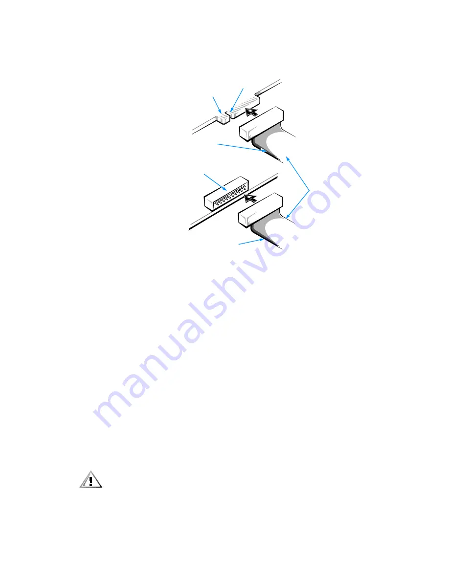
The drive’s interface connector is a card-edge connector or a header connector, as 
shown in Figure 7-5. 

)LJXUH  'ULYH ,QWHUIDFH &RQQHFWRUV

When attaching the interface cable to a drive, be sure to match the colored strip on 
the cable to pin 1 of the drive’s interface connector. For the location of pin 1 on the 
drive’s interface connector, see the documentation that came with the drive.

When disconnecting an interface cable from the system board, be sure to press in on 
the locking tabs on the cable connector before disconnecting the cable. When attach-
ing an interface cable to the system board, be sure that the locking tabs snap into 
place, ensuring that the cable is firmly attached to the connector on the system board.

Most interface connectors are keyed for correct insertion; that is, a notch or a missing 
pin on one connector matches a tab or a filled-in hole on the other connector. Keying 
ensures that the pin-1 wire in the cable (indicated by the colored strip along one edge 
of the cable) goes to the pin-1 end of the connector.

The pin-1 end of a card-edge connector is usually identified by a notch cut about a 
quarter of an inch from the end of the connector, as shown in Figure 7-5. A header 
connector is usually keyed by the omission of one of its pins, while the corresponding 
hole is filled in on the cable connector.

The pin-1 end of a connector on a board or a card is usually indicated by a silk-
screened “1” printed directly on the board or card. 

&$87,21 :KHQ FRQQHFWLQJ DQ LQWHUIDFH FDEOH GR QRW UHYHUVH WKH LQWHUIDFH

FDEOH GR QRW SODFH WKH FRORUHG VWULS DZD\ IURP SLQ  RQ WKH FRQQHFWRU

5HYHUVLQJ WKH FDEOH SUHYHQWV WKH GULYH IURP RSHUDWLQJ DQG FRXOG GDPDJH

WKH FRQWUROOHU WKH GULYH RU ERWK

header connector 
on drive

interface
cables

card-edge connector on drive

colored strip

notch

colored strip

Summary of Contents for OptiPlex E1

Page 1: ... ZZZ GHOO FRP HOO 2SWL3OH 0DQDJHG 3 5 5 1 1 167 7 21 8 ...

Page 2: ... trademarks and Windows for Workgroups is a trademark of Microsoft Corporation IBM and OS 2 are registered trademarks of International Business Machines Corporation 3Com EtherLink and EtherDisk are registered trademarks and Fast EtherLink is a trademark of 3Com Corporation VESAis aregistered trademarkofVideoElectronics StandardsAssociation UNIXis a registeredtrademark of UNIX System Laboratories I...

Page 3: ...vailable in your location Before working inside the computer unplug the system to help prevent electric shock or system board damage Certain system board components continue to receive power any time the computer is connected to AC power To help avoid possible damage to the system board wait 5 seconds after turning off the system before disconnecting a device from the computer To help prevent elec...

Page 4: ...tance usually 510 to 610 millimeters 20 to 24 inches from your eyes Make sure the monitor screen is at eye level or slightly lower when you are sitting in front of the monitor Adjust the tilt of the monitor its contrast and brightness settings and the lighting around you such as overhead lights desk lamps and the curtains or blinds on nearby windows to minimize reflections and glare on the monitor...

Page 5: ...HP ERDUG ZDLW VHFRQGV DIWHU WXUQLQJ RII WKH V VWHP EHIRUH UHPRYLQJ D FRPSRQHQW IURP WKH V VWHP ERDUG RU GLVFRQQHFWLQJ D SHULSKHUDO GHYLFH IURP WKH FRPSXWHU 7XUQ RII RXU FRPSXWHU DQG DQ SHULSKHUDOV LVFRQQHFW RXU FRPSXWHU DQG SHULSKHUDOV IURP WKHLU SRZHU VRXUFHV OVR GLVFRQQHFW DQ WHOHSKRQH RU WHOHFRPPXQLFDWLRQ OLQHV IURP WKH FRPSXWHU Doing so reduces the potential for personal injury or shock monito...

Page 6: ... LVFKDUJH Static electricity can harm delicate components inside your computer To prevent static damage discharge static electricity from your body before you touch any of your computer s electronic components such as the microprocessor You can do so by touching an unpainted metal surface on the computer chassis As you continue to work inside the computer periodically touch an unpainted metal surf...

Page 7: ...ppear throughout this document to remind you of these precautions 87 21 7XUQ RII WKH FRPSXWHU DQG XQSOXJ LW IURP WKH HOHFWULFDO RXWOHW 6HH 3URWHFWLQJ JDLQVW OHFWURVWDWLF LVFKDUJHµ LQ WKH VDIHW LQVWUXFWLRQV DW WKH IURQW RI WKLV JXLGH ...

Page 8: ...x ...

Page 9: ...fault configuration of the system s integrated video and audio controllers or who want to connect their system to a network should read Chapter 4 Using Integrated Devices This chapter describes the configuration software provided for the integrated video and audio controllers and provides information on connecting the system to a network configuring the net work interface controller NIC and instal...

Page 10: ...puter s back panel The Diagnostics and Troubleshooting Guide includes troubleshooting procedures and instructions for using the Dell Diagnostics to test your computer system You may also have one or more of the following documents NOTE Documentation updates are sometimes included with your system to describe changes to your system or software Always read these updates before consulting any other d...

Page 11: ...he labeling that appears on the keys on a keyboard are enclosed in angle brackets Example Enter Key combinations are series of keys to be pressed simultaneously unless other wise indicated to perform a single function Example Ctrl Alt Enter Commands presented in lowercase bold are for reference purposes only and are not intended to be typed when referenced Example Use the format command to In cont...

Page 12: ... can be a system message for example or it can be text that you are instructed to type as part of a command referred to as a command line Screen text is presented in the Courier New font Example The following message appears on your screen No boot device available Example Type md c programs and press Enter Variables are placeholders for which you substitute a value They are presented in italics Ex...

Page 13: ...ity Cable Slot and Padlock Ring 1 8 Passwords 1 9 Using the Power Switch 1 9 Using the Optional Stand for Vertical Orientation 1 10 Energy Star Compliance 1 11 Important Note for Windows 95 Users 1 11 Intel PIIX4e INF Update Installer for Windows 95 1 12 Accessing Online Documentation 1 13 Getting Help 1 14 KDSWHU 8VLQJ WKH 6 VWHP 6HWXS 3URJUDP Entering the System Setup Program 2 1 System Setup Sc...

Page 14: ...PU Speed 2 9 Integrated Devices 2 9 Sound 2 9 Network Interface Controller 2 9 Mouse Port 2 9 Serial Port 1 and Serial Port 2 2 10 Parallel Port 2 10 Parallel Port Mode 2 10 IDE Drive Interface 2 10 Diskette Interface 2 11 PC Speaker 2 11 Video DAC Snoop 2 11 System Security 2 11 System Password 2 11 Password Status 2 12 Setup Password 2 12 Chassis Intrusion 2 12 Keyboard NumLock 2 13 Report Keybo...

Page 15: ...bout the ICU 3 3 ICU Database 3 3 When to Run the ICU 3 3 Preparing to Use the ICU 3 4 Backing Up the ICU Diskette 3 4 Starting the ICU 3 5 Accessing Help 3 5 Making Selections in the ICU 3 5 Adding a Listed Card 3 6 Adding an Unlisted Card 3 9 Modifying a Card 3 11 Removing a Card 3 13 Viewing Resources 3 14 Saving the System Configuration 3 15 Exiting From the ICU 3 15 Locking and Unlocking Card...

Page 16: ...moving the Expansion Card Cage 5 11 Replacing the Expansion Card Cage 5 12 KDSWHU QVWDOOLQJ 6 VWHP RDUG 2SWLRQV Expansion Cards 6 2 Expansion Slots 6 2 Installing an Expansion Card 6 3 Removing an Expansion Card 6 5 Adding Memory 6 6 Performing a Memory Upgrade 6 7 Installing a DIMM 6 9 Removing a DIMM 6 9 Adding Video Memory 6 10 Replacing the System Battery 6 11 KDSWHU QVWDOOLQJ ULYHV Removing a...

Page 17: ...F JOTUSVLDKF CF QJFD FËTUXB C 6 NOM 024 Information Mexico Only C 7 Información para NOM 024 únicamente para México C 8 SSHQGL DUUDQWLHV DQG 5HWXUQ 3ROLF Limited Three Year Warranty U S and Canada Only D 1 Coverage During Year One D 1 Coverage During Years Two and Three D 2 General D 2 Total Satisfaction Return Policy U S and Canada Only D 3 QGH LJXUHV Figure 1 1 Dell OpenManage Program 1 6 Figure...

Page 18: ...Card Connectors 6 3 Figure 6 4 Removing the Filler Bracket 6 4 Figure 6 5 Installing an Expansion Card 6 4 Figure 6 6 DIMMs and DIMM Sockets 6 6 Figure 6 7 Installing a DIMM 6 9 Figure 6 8 Removing a DIMM 6 9 Figure 6 9 Installing a Video Memory Upgrade Module 6 10 Figure 6 10 System Battery and Battery Socket 6 13 Figure 7 1 Drive Locations 7 1 Figure 7 2 Removing the Front Panel Insert for the 5...

Page 19: ...1 ICU Keys 3 6 Table 5 1 System Board Jumper Settings 5 9 Table 5 2 System Board and Riser Board Connectors and Sockets 5 10 Table 6 1 Sample DIMM Configuration Options 6 7 Table A 1 Technical Specifications A 1 Table B 1 Configuration Utility Messages B 1 Table B 2 Configuration Manager Messages B 6 ...

Page 20: ...xxii ...

Page 21: ...he Intel Celeron microprocessor includes MMX technology designed to handle complex multimedia and communications software This microprocessor incorpo rates new instructions and data types as well as a technique called single instruction multiple data SIMD that allows the microprocessor to process multiple data elements in parallel thereby improving overall system performance The Celeron microproce...

Page 22: ...and on weekends when network traffic is at a minimum For more information refer to Chapter 2 Using the System Setup Program Universal Serial Bus USB capability which can simplify connecting peripheral devices such as mice printers and computer speakers The USB connectors on your computer s back panel which are enabled by default provide a single connection point for multiple USB compliant devices ...

Page 23: ...drives as well as devices such as advanced technology attachment ATA 33 hard disk drives EIDE CD ROM drives and EIDE tape drives Two high performance serial ports and one bidirectional parallel port for connect ing external devices The parallel port is fully Enhanced Capabilities Port ECP compliant A Personal System 2 PS 2 style keyboard port and a PS 2 compatible mouse port 7DEOH 9LGHR 0HPRU 5HTX...

Page 24: ...er s Guide The System Setup program for quickly viewing and changing the system configu ration information for your system For more information on this program see Chapter 2 Using the System Setup Program An Auto Power On utility that enables your system to perform routine tasks auto matically in your absence For more information on this utility see your online System User s Guide Enhanced securit...

Page 25: ...can use to reinstall or reconfigure the software You can use this same menu to remove diskette image files individual files that correspond to each diskette in a program diskette set to reclaim space on the computer s hard disk drive For more information on making program diskette sets see the online help provided in the Dell Program Diskette Maker which is located in the Dell Accessories folder T...

Page 26: ... and administrator versions The Dell OpenManage administrator version enables system administrators to view manage and inventory remote sys tems in a Dell DMI client network and incorporates the following manageability features which are based on the DMI 2 0 specification DXOW 0DQDJHPHQW Fault Management features of Dell OpenManage include Alerts to warn you about events generated by SMART drives ...

Page 27: ... to a user defined directory Support for the application used to create user definable attributes UDAs VVHW 0DQDJHPHQW Asset Management features of the Dell OpenManage include Support that enables network administrators to remotely view enter and modify an asset tag number for a remote system in a Dell DMI network Automated and manual mapping of one or more groups to a user defined directory 6HFXU...

Page 28: ...he computer system automatically on certain days of the week at a preset time You can set Auto Power On to turn on the system either every day or every Monday through Friday NOTE This feature does not work if the system is shut off using a power strip or surge protector 6HFXULW HDWXUHV Your Dell OptiPlex E1 system has the following integrated security features KDVVLV QWUXVLRQ A built in chassis in...

Page 29: ... you to set a user defined password to restrict access to the system Additional protection is available through the System Setup program When the Setup Password category is set to Enabled Password Status allows you to prevent the system password from being changed or disabled at boot time For more information see Chapter 2 Using the System Setup Program 8VLQJ WKH 3RZHU 6ZLWFK If the system does no...

Page 30: ...on the stand as shown in Figure 1 3 Align the large round hole in the stand with the securing button on the side of the cover and align the captive thumb screw in the stand with the screw hole in the cover LJXUH WWDFKLQJ WKH 2SWLRQDO 6WDQG IRU 9HUWLFDO 2ULHQWDWLRQ As you lower the stand into place make sure that the locator pin see Figure 1 3 fits into the corner hole of the hole pattern as shown ...

Page 31: ...limits set by the EPA s Energy Star Computers program LJXUH QHUJ 6WDU PEOHP The EPA s Energy Star Computers program is a joint effort between the EPA and com puter manufacturers to reduce air pollution by promoting energy efficient computer products The EPA estimates that use of Energy Star computer products can save computer users up to two billion dollars annually in electricity costs In turn th...

Page 32: ...orporate networks and you must down load Windows 95 from a server to client systems make sure that you have the Windows 95 backup media for the OptiPlex E1 system on your server before downloading QWHO 3 H 1 8SGDWH QVWDOOHU IRU LQGRZV NOTE The following procedure applies only to versions of Windows 95 installed by Dell If you must reinstall Windows 95 on your computer system you also need to run t...

Page 33: ... the system configuration settings have changed and asks if you want to restart your system OLFN 2 WR UHVWDUW WKH V VWHP FFHVVLQJ 2QOLQH RFXPHQWDWLRQ The online System User s Guide installed on your hard disk drive contains information on the following topics Using the online System User s Guide System features Using drivers and utilities Using the audio controller Using the System Setup program C...

Page 34: ...ols to help you if you don t understand a procedure described in this guide or if your system does not perform as expected For informa tion on these help tools see the chapter titled Getting Help in your Diagnostics and Troubleshooting Guide or the Contacting Dell section in the online System User s Guide ...

Page 35: ...r example the time or date on your system You can view the current settings at any time When you change a setting in many cases you must reboot the system before the change takes effect After you set up your system run the System Setup program to familiarize yourself with your system configuration information and optional settings Dell recommends that you print the System Setup screen by pressing ...

Page 36: ...in four areas Title box The box at the top of the screen lists the system name System data The two boxes below the title box display information about your system such as the basic input output system BIOS revision number Configuration options The box under the system data boxes lists categories that define the installed hardware in your computer Fields beside the categories contain options or val...

Page 37: ...he changes take effect immediately Exits the System Setup program at the System Setup screen if no settings in any option were changed Provides exit menu options if changes were made Highlight a menu option to select it and press Enter to activate it Save Changes and Exit option exits the System Setup program and reboots the system implementing any changes you have made Discard Changes and Exit op...

Page 38: ... Secondary Drive 1 Not Installed Hard Disk Drive Sequence ENTER Boot Sequence ENTER System Memory 32 MB SDRAM Video Memory 2 MB SGRAM Reserved Memory None Reserved CPU Speed 266 MHz Integrated Devices ENTER System Security ENTER Keyboard NumLock On Report Keyboard Errors Report Auto Power On Disabled Wakeup On LAN Off Power Management Disabled Asset Tag ASSET TAG Dell Computer Corporation www dell...

Page 39: ... externally accessible drive bay Diskette Drive B is any drive installed in the bottom externally accessible drive bay that is connected to the system s diskette tape drive interface The category options always match the physical locations of the drives in your com puter the first drive listed is the top drive in your computer The Diskette Drive A and Diskette Drive B categories have the following...

Page 40: ...rformance HYLFHV For EIDE hard disk drives the system provides an automatic drive type detect feature To use this feature for Primary Drive 0 highlight the Primary Drive 0 category and type a for automatic to use it for Primary Drive 1 highlight the Primary Drive 1 category and type a In each case the category setting changes to Auto After the system reboots the System Setup program automatically ...

Page 41: ...ight each of the parameter fields in succession and enter the appropriate number for each field NOTE The User 1 and User 2 drive types can be used for both the Primary and Sec ondary Drive 0 and Drive 1 categories However if you select the User 1 or User 2 drive type you may not obtain optimum hard disk drive performance Also the User 1 and User 2 drive types cannot be used for hard disk drives gr...

Page 42: ... to boot from the next device in the boot sequence list 2QERDUG 1 Selecting Onboard NIC causes the system to try booting from the integrated net work interface controller NIC first 3 Selecting PXE Preboot eXecution Environment causes the system to boot from the integrated network interface controller NIC first If a boot routine is not avail able from the network server the system tries to boot fro...

Page 43: ... immediately rebooting the system is not required To toggle between the rated processor speed and the compatibility speed while the system is running in real mode press Ctrl Alt For keyboards that do not use American English press Ctrl Alt QWHJUDWHG HYLFHV Integrated Devices configures the devices integrated into the system board Press Enter to configure these options 6RXQG Sound determines whethe...

Page 44: ...f If you are using the Microsoft Windows 95 or IBM OS 2 operating system you cannot use both serial ports at the same time For more information about built in ports port designations IRQs and the remapping of ports see Connecting External Devices in your online System User s Guide 3DUDOOHO 3RUW Parallel Port configures the system s built in parallel port This category can be set to 378h the defaul...

Page 45: ...lt in diskette drive controller The system can still read from the drives When this option is selected the Auto option whereby the system turns off the built in diskette drive controller as necessary is also in effect Selecting Off turns off the built in diskette tape drive controller this option is used pri marily for troubleshooting purposes 3 6SHDNHU PC Speaker determines whether the on board s...

Page 46: ...ng Ctrl Enter To unlock the system password you must enter the setup password in the Setup Password category and then change the Password Status category to Unlocked In this state the system password can be disabled at system start up by pressing Ctrl Enter and then changed through the System Password category 6HWXS 3DVVZRUG Setup Password lets you restrict access to your computer s System Setup p...

Page 47: ...rd errors during the POST which is a series of tests that the system performs on the hardware each time you turn on the system or press the reset button This category is useful when applied to self starting servers or host systems that have no permanently attached keyboard In these situations selecting Do Not Report suppresses all error messages relating to the keyboard or to the keyboard con trol...

Page 48: ...itors activity of a mouse connected to the PS 2 compatible mouse port By setting Power Management to Maximum Regular or Minimum you can set pre defined time out periods see Table 2 2 for the two successive monitor shutdown stages standby and off NOTE Each monitor manufacturer defines the details of the shutdown stages for its own monitors But in all cases power consumption decreases with each stag...

Page 49: ...ag number has been assigned You can use the Asset Tag utility which is included with your software support utilities to enter an asset tag number up to ten characters long into NVRAM For information on using the utility see Using Drivers and Utilities in your online System User s Guide 6 VWHP DWD DWHJRULHV The following categories which are not selectable display information about the system The m...

Page 50: ...ust remove the computer cover to change a jumper setting that disables the system password feature see Dis abling a Forgotten Password found later in this chapter Note that you erase the setup password at the same time 87 21 I RX OHDYH RXU V VWHP UXQQLQJ DQG XQDWWHQGHG ZLWKRXW KDYLQJ D V VWHP SDVVZRUG DVVLJQHG RU LI RX OHDYH RXU FRPSXWHU XQORFNHG VR WKDW VRPHRQH FDQ GLVDEOH WKH SDVVZRUG E FKDQJLQJ...

Page 51: ...G DQG SUHVV QWHU The system password is now assigned and is Enabled You can exit the System Setup program and begin using your system Password protection takes effect after the system reboots 8VLQJ RXU 6 VWHP 3DVVZRUG WR 6HFXUH RXU 6 VWHP Whenever you turn on your system press the reset button or reboot the system by pressing the Ctrl Alt Del key combination the following prompt appears on the scr...

Page 52: ... Status found earlier in this chapter HOHWLQJ RU KDQJLQJ DQ LVWLQJ 6 VWHP 3DVVZRUG To delete or change an existing system password follow these steps QWHU WKH 6 VWHP 6HWXS SURJUDP DQG YHULI WKDW WKH 3DVVZRUG 6WDWXV VHWWLQJ LV VHW WR 8QORFNHG Enter the System Setup program by pressing F2 For instructions on changing the setting for Password Status see Password Status found earlier in this chapter L...

Page 53: ...Forgotten Password found later in this chapter Note that you erase the system password at the same time VVLJQLQJ D 6HWXS 3DVVZRUG A setup password can be assigned or changed only when the Setup Password cate gory is set to Not Enabled To assign a setup password follow these steps QWHU WKH 6 VWHP 6HWXS SURJUDP LJKOLJKW WKH 6 VWHP 6HFXULW FDWHJRU DQG SUHVV QWHU LJKOLJKW WKH 6HWXS 3DVVZRUG FDWHJRU DQ...

Page 54: ...an existing system password NOTE You can use the Password Status category in conjunction with Setup Password to protect the system password from unauthorized changes For more information see Password Status found earlier in this chapter HOHWLQJ RU KDQJLQJ DQ LVWLQJ 6HWXS 3DVVZRUG To delete or change an existing setup password follow these steps QWHU WKH 6 VWHP 6HWXS SURJUDP LJKOLJKW WKH 6 VWHP 6HF...

Page 55: ...U SRZHU VRXUFHV DQG WKHQ WXUQ WKHP RQ Booting your system with the PSWD jumper plug removed erases the existing password s NOTE After you remove and replace the cover the chassis intrusion detector will cause the following message to be displayed at the next system start up ALERT Cover was previously removed 7R UHVHW WKH FKDVVLV LQWUXVLRQ GHWHFWRU HQWHU WKH 6 VWHP 6HWXS SURJUDP DQG UHVHW KDVVLV QW...

Page 56: ...een assigned by someone else contact your network administrator for information on resetting the chassis intrusion detector VVLJQ D QHZ V VWHP DQG RU VHWXS SDVVZRUG To assign a new system password see Assigning a System Password found earlier in this chapter To assign a new setup password see Assigning a Setup Password found earlier in this chapter 5HVSRQGLQJ WR UURU 0HVVDJHV If an error message a...

Page 57: ...support Therefore some Plug and Play cards such as modem sound and net work cards may not work with Windows NT If your system is running a Dell installed Windows NT operating system and you want to use Plug and Play expansion cards Dell recommends that you use the card manufacturer s configuration utility to set the card to legacy mode enter the card s resources through the manufacturer s utility ...

Page 58: ...I RU UHPRYH D FDUG RU YLHZ UHVRXUFHV IRU D FDUG RU RWKHU GHYLFH Depending on what you need to accomplish with the ICU you may need to per form one or more of these tasks If you are adding a non Plug and Play ISA expansion card see your online System User s Guide or Adding a Listed Card found later in this chapter for detailed instructions If the card you are adding does not have a configuration fi...

Page 59: ...ation 8 DWDEDVH The ICU provides a database of configuration files for a large variety of non Plug and Play ISA expansion cards The database is located in the db subdirectory Listed cards are non Plug and Play ISA expansion cards that have configuration files stored in this database Unlisted cards are non Plug and Play ISA expansion cards that do not have configura tion files stored in the ICU dat...

Page 60: ...create a program diskette from the diskette image see the online help provided in the Program Diskette Maker which is available in the Dell Accessories folder I RX ZDQW WR XVH RXU PRXVH ZLWK WKH 8 FRS RXU PRXVH GULYHU ILOH PRXVH H H WR RXU 8 GLVNHWWH 0DNH D EDFNXS FRS RI RXU 8 GLVNHWWH DV GHVFULEHG LQ WKH QH W VXE VHFWLRQ DFNLQJ 8S WKH 8 LVNHWWH µ Use the backup copy whenever you run the utility s...

Page 61: ...To redisplay the last message you received from the ICU select Previous Mes sage from the Help menu 0DNLQJ 6HOHFWLRQV LQ WKH 8 The ICU window is the main window of the utility and the starting point for making expansion card changes This window lists all non Plug and Play ISA Plug and Play and PCI expansion cards currently installed in the computer The ICU window con tains menus and a tool bar as ...

Page 62: ...RU RI FDUG WKDW RX ZDQW WR DGG I RX FOLFNHG GG LQ VWHS FOLFN 2 A dialog box like the one in Figure 3 2 appears listing the names of all available cards of that type LJXUH GG 1HWZRUN DUG LDORJ R 6HOHFW WKH QDPH RI WKH FDUG RX ZDQW WR DGG If the card is not listed see the next section Adding an Unlisted Card 7DEOH 8 H V H V FWLRQ Alt x y Displays the menu containing the underlined letter x and per f...

Page 63: ...XUFHV RXUVHOI FOLFN GYDQFHG The Card Configuration dialog box see Figure 3 3 displays all resources used by the card Some cards have multiple functions each having one or more resources associated with it For example a communications card can have fax modem and scanner functions each of which may have one or more associated resources LJXUH DUG RQILJXUDWLRQ LDORJ R 7R FKDQJH DQ RI WKH UHVRXUFH VHWW...

Page 64: ... resources available For example if you are offered the Disabled option and select it all resource values are blank indicat ing that a disabled setting uses no resources LJXUH YDLODEOH 6HWWLQJV LVW R 7R FKDQJH LQGLYLGXDO UHVRXUFH YDOXHV IRU WKH FXUUHQW FRQILJXUDWLRQ VHW WLQJ VHOHFW WKH UHVRXUFH YDOXH WKDW RX ZDQW WR FKDQJH DQG FOLFN WKH 2SWLRQV EXWWRQ ORFDWHG EHORZ WKH UHVRXUFH YDOXHV VHH LJXUH Fo...

Page 65: ...U WKH IXQFWLRQ NOTE After modifying the system configuration you must turn off the system to install remove or change jumper settings on the non Plug and Play ISA expansion cards to match the settings you selected in the ICU GGLQJ DQ 8QOLVWHG DUG Unlisted cards are non Plug and Play ISA expansion cards that do not have configura tion files stored in the ICU database NOTE If you want to add a confi...

Page 66: ...e button changes to Add Inter rupt When you click this button a Specify dialog box in this case Specify Interrupt appears Figure 3 7 shows the Configure Unlisted Card dialog box with the Specify Interrupt dialog box opened LJXUH 6SHFLI QWHUUXSW LDORJ R If you are providing a value for the interrupt request IRQ or direct memory access DMA resource click the down arrow beneath Available Resources A ...

Page 67: ...LFN 9LHZ XQWLO RX ILQG DQRWKHU FDUG XVLQJ D UHVRXUFH YDOXH WKDW LV DOORZHG IRU WKH XQOLVWHG FDUG 5HDVVLJQ WKH UHVRXUFH VHWWLQJ IRU WKLV RWKHU FDUG XVLQJ WKH SURFH GXUH LQ WKH QH W VHFWLRQ 0RGLI LQJ D DUG µ 7KHQ PRGLI WKH UHVRXUFH VHWWLQJV IRU WKH XQOLVWHG FDUG VR WKDW LW XVHV DQ DOORZDEOH YDOXH NOTE After modifying the system configuration you must turn the system off to install remove or change j...

Page 68: ...G HDUOLHU LQ WKLV FKDSWHU 7KHQ FRQWLQXH ZLWK VWHS RI WKLV SURFHGXUH OLFN 2 WR FRPSOHWH WKH FDUG PRGLILFDWLRQV DQG UHWXUQ WR WKH 8 ZLQGRZ You have completed this procedure do not proceed to step 5 7R DGG PRGLI RU UHPRYH D UHVRXUFH YDOXH VHOHFW WKH ER EHQHDWK WKH UHVRXUFH WR EH DVVLJQHG DQG WKHQ FOLFN GG 0RGLI RU 5HPRYH UHVSHFWLYHO For example if you click the box beneath IRQ the Add Modify and Remo...

Page 69: ...A expansion cards to match the settings you selected in the ICU 5HPRYLQJ D DUG Before you remove a non Plug and Play ISA expansion card from your computer you must use the ICU to remove the card from the system configuration NOTE When you remove a Plug and Play or PCI expansion card from your computer you do not need to run the ICU To remove a Plug and Play or PCI expansion card complete steps 2 t...

Page 70: ...hich card uses a particular resource shown in the System Resource Usage dialog box select the resource in question and then click Used By Card The Card Resource Usage dialog box appears with the information To view the resources that a particular card is using select the card from the list dis played in the ICU window and then select Card Resources from the View menu or click View The Card Resourc...

Page 71: ...ards are dynamic which means that they are allocated resources at system start up Device drivers that do not support this dynamic card configuration are referred to as static device drivers To determine whether your expansion card has static device drivers check the docu mentation that came with the drivers If you are using a static device driver you need to permanently associate resources with a ...

Page 72: ...nsion Card in Chapter 6 6WDUW WKH 8 See Starting the ICU found earlier in this chapter 6HOHFW RFNLQJ QDEOHG IURP WKH GYDQFHG PHQX LQ WKH 8 ZLQGRZ A check mark next to Locking Enabled signifies that the feature is active a Lock button appears on the tool bar 6HOHFW WKH 3OXJ DQG 3OD RU 3 H SDQVLRQ FDUG WKDW RX ZDQW WR ORFN RU XQORFN IURP WKH DUGV RQILJXUHG LQ 6 VWHP OLVW OLFN 0RGLI RU VHOHFW 0RGLI D...

Page 73: ...stalled on your hard disk drive For information on reinstalling video drivers see Using Drivers and Utilities in your online System User s Guide For instructions on changing to a differ ent video driver see your operating system documentation XGLR RQWUROOHU Your system may have an integrated Crystal CS4236B audio controller and audio drivers for the following operating systems Microsoft Windows 3 ...

Page 74: ...in a steady on state A green link integrity indicator lights up when there is a good connection between the network and the NIC When the green indicator is off the computer is not detecting a physical connection to the network LJXUH 2 3RUWV DQG RQQHFWRUV 1HWZRUN DEOH 5HTXLUHPHQWV Your computer s NIC connector an RJ45 connector located on the back panel is designed for attaching an unshielded twist...

Page 75: ...ivers for systems running a Dell installed Windows NT 4 0 or Windows 95 operating system are automatically detected and installed Instructions for reconfiguring the NIC driver are included in the following subsections The 3Com EtherDisk XL version 3 01 diskettes provided by Dell are compatible with the 3C905 family of NICs Do not attempt to use 3Com EtherDisk XL diskettes from any other source Use...

Page 76: ...DFFHVV WKH 6HOHFW 1HWZRUN GDSWHU ZLQGRZ OLFN DYH LVN QVHUW GLVNHWWH LQWR GULYH W SH a DQG WKHQ FOLFN 2 6HOHFW RP DVW WKHU LQN WKHU LQN 3 XV 0DVWHU 1 7 DQG WKHQ FOLFN 2 KHQ SURPSWHG IRU GLVNHWWH FOLFN 2 KHQ WKH RSHUDWLQJ V VWHP KDV ILQLVKHG FRS LQJ ILOHV IURP GLVNHWWH FOLFN ORVH LQ WKH LQGRZV HOFRPH VFUHHQ DQG UHPRYH WKH GLVNHWWH IURP GULYH 7KHQ FOLFN ORVH LQ WKH 1HWZRUN ZLQGRZ KHQ SURPSWHG HQWHU L...

Page 77: ...HOHFW RP DVW WKHU LQN 1 7 DQG WKHQ FOLFN 2 KHQ SURPSWHG UHPRYH GLVNHWWH IURP WKH GLVNHWWH GULYH DQG LQVHUW GLVNHWWH OLFN ORVH LQ WKH LQGRZV HOFRPH VFUHHQ DQG WKHQ FOLFN ORVH DJDLQ LQ WKH 1HWZRUN ZLQGRZ I RX DUH SURPSWHG HQWHU LQIRUPDWLRQ DERXW RXU VSHFLILF QHWZRUN See your system administrator for more information OLFN HV LQ WKH 1HWZRUN 6HWWLQJV KDQJH ZLQGRZ WR UHVWDUW RXU V VWHP LQGRZV 1 NOTE If ...

Page 78: ... FOLFN RQWURO 3DQHO 7KHQ GRXEOH FOLFN WKH 6 VWHP LFRQ Q WKH 6 VWHP 3URSHUWLHV ZLQGRZ FOLFN WKH HYLFH 0DQDJHU WDE Q WKH OLVW RI V VWHP GHYLFHV GRXEOH FOLFN 2WKHU HYLFHV 7KHQ FOLFN 3 WKHUQHW RQWUROOHU OLFN 3URSHUWLHV WR DFFHVV WKH 3 WKHUQHW RQWUROOHU ZLQGRZ OLFN WKH ULYHU WDE DQG WKHQ FOLFN 8SGDWH ULYHU The Update Device Driver Wizard starts QVHUW GLVNHWWH LQWR GULYH DQG VHOHFW HV 5HFRPPHQGHG OLFN 1...

Page 79: ...he System Setup Program for more information 6WDUW LQGRZV IRU RUNJURXSV Q WKH 0DLQ SURJUDP JURXS GRXEOH FOLFN WKH LQGRZV 6HWXS LFRQ OLFN RQWLQXH WR DFFHVV WKH LQGRZV 6HWXS VFUHHQ 6HOHFW KDQJH 1HWZRUN 6HWWLQJV IURP WKH 2SWLRQV PHQX URP WKH 1HWZRUN 6HWXS ZLQGRZ FOLFN 1HWZRUNV 7KHQ FOLFN QVWDOO 0LFURVRIW LQGRZV 1HWZRUN DQG FOLFN 2 OLFN ULYHUV WR DFFHVV WKH 1HWZRUN ULYHUV GLDORJ ER OLFN GG GDSWHU WR D...

Page 80: ...ULYH RQQHFW WKH QHWZRUN FDEOH WR WKH EDFN RI RXU FRPSXWHU See Network Cable Requirements found earlier in this section for more information 9HULI WKDW WKH 1 LV HQDEOHG LQ WKH 6 VWHP 6HWXS SURJUDP See Chapter 2 Using the System Setup Program for more information RQILJXUH WKH 1 DQG LQVWDOO WKH QHWZRUN GULYHUV E UXQQLQJ WKH RP QVWDOO SURJUDP LQVWDOO H H ORFDWHG RQ WKH 1 GULYHU GLVNHWWH 5XQ WKH 1HWZRU...

Page 81: ...Using Integrated Devices 4 9 6HOHFW WKH DSSURSULDWH IUDPH W SH IURP WKH 9DOXH PHQX DFFRUGLQJ WR RXU QHWZRUN UHTXLUHPHQWV ROORZ WKH LQVWUXFWLRQV RQ RXU VFUHHQ WR FRPSOHWH WKH FRQILJXUDWLRQ ...

Page 82: ...4 10 Dell OptiPlex E1 Managed PC Reference and Installation Guide ...

Page 83: ...this section every time you install a hardware option inside your computer Read this section carefully because the information is not repeated in detail elsewhere in this guide 6DIHW LUVW RU RX DQG RXU RPSXWHU Working inside your computer is safe if you observe the following precautions 51 1 25 285 3 5621 6 7 1 3527 7 21 2 285 48 30 17 HIRUH VWDUWLQJ WR ZRUN RQ RXU FRPSXWHU SHUIRUP WKH IROORZLQJ V...

Page 84: ... carton you may find it wrapped in anti static packing material designed to protect it from electrostatic damage Do not remove the packing material until you are ready to install the option 87 21 7XUQ RII WKH FRPSXWHU DQG XQSOXJ LW IURP WKH HOHFWULFDO RXWOHW 6HH 3URWHFWLQJ JDLQVW OHFWURVWDWLF LVFKDUJHµ LQ WKH VDIHW LQVWUXFWLRQV DW WKH IURQW RI WKLV JXLGH 5HPRYLQJ WKH RPSXWHU RYHU To remove the com...

Page 85: ...sengage the plastic hooks that secure the cover to the front of the chassis and lift the cover away LJXUH 5HPRYLQJ WKH RPSXWHU RYHU 5HSODFLQJ WKH RPSXWHU RYHU To replace the computer cover follow these steps KHFN DOO FDEOH FRQQHFWLRQV HVSHFLDOO WKRVH WKDW PLJKW KDYH FRPH ORRVH GXULQJ RXU ZRUN ROG FDEOHV RXW RI WKH ZD VR WKDW WKH GR QRW FDWFK RQ WKH FRPSXWHU FRYHU 0DNH VXUH FDEOHV DUH QRW URXWHG RY...

Page 86: ...t surface It is difficult to align the cover if the front of the computer is hanging over the edge of a table LJXUH 5HSODFLQJ WKH RPSXWHU RYHU I RX DUH XVLQJ WKH RSWLRQDO IORRU VWDQG UHDWWDFK LW See Using the Optional Stand for Vertical Orientation in Chapter 1 for instructions I RX DUH XVLQJ D SDGORFN WR VHFXUH RXU V VWHP UHLQVWDOO WKH SDGORFN OHDU WKH FKDVVLV LQWUXVLRQ DOHUW PHVVDJH Enter the Sy...

Page 87: ...e flat ribbon cable in Figure 5 5 is typical of the interface cables for internal drives An interface cable connects a drive to a connector on the system board or on an expansion card The system board the large printed circuit board at the bottom of the chassis holds the computer s control circuitry and other electronic components Some hardware options are installed directly onto the system board ...

Page 88: ...e plug is pushed down over two pins the jumper is referred to as jumpered In some documents the jumper setting may be shown in text as two numbers such as 1 2 The number 1 is printed on the circuit board so that you can identify each pin number based on the location of pin 1 Figure 5 6 shows the location and default settings of the jumper blocks on your sys tem board See Table 5 1 for the designat...

Page 89: ... on the appropriate side of the switch In either case do not use a pen pencil or other object that might leave a residue on the switch LJXUH QVLGH WKH KDVVLV integrated NIC connector parallel port connector USB connectors mouse connector keyboard connector padlock ring back of computer video connector serial port 1 connector DC power cable drive interface cable AC power receptacle fan guard securi...

Page 90: ...5 8 Dell OptiPlex E1 Managed PC Reference and Installation Guide LJXUH 6 VWHP RDUG XPSHUV jumpered unjumpered ...

Page 91: ...hen the microprocessor s internal speed is 266 MHz 300MHZ Jumpered when the microprocessor s internal speed is 300 MHz 333MHZ Jumpered when the microprocessor s internal speed is 333 MHz One set of the speed jumper pins must have a jumper plug installed otherwise the system will operate at an undetermined speed NOTE For the full name of an abbreviation or acronym used in this table see the Glossar...

Page 92: ...onnector on riser board IDEn EIDE interface connector INTRUSION Chassis intrusion switch connector ISAn ISA expansion card connector on riser board KYBD Keyboard connector LINE IN Audio line in jack optional LINE OUT Audio line out jack amplified source optional MIC Microphone jack optional MONITOR Video connector MOUSE Mouse connector P1 Wakeup On LAN power connector on riser board PANEL Control ...

Page 93: ...RXW OHW 6HH 3URWHFWLQJ JDLQVW OHFWURVWDWLF LVFKDUJHµ LQ WKH VDIHW LQVWUXFWLRQV DW WKH IURQW RI WKLV JXLGH KHFN DQ FDEOHV FRQQHFWHG WR H SDQVLRQ FDUGV WKURXJK WKH EDFN SDQHO RSHQLQJV LVFRQQHFW DQ FDEOHV WKDW ZLOO QRW UHDFK WR ZKHUH WKH FDJH PXVW EH SODFHG XSRQ UHPRYDO IURP WKH FKDVVLV POWER_1 Main power input connector POWER_2 3 3 V power input connector RISER Riser board connector SERIALn Serial p...

Page 94: ...KW SRVLWLRQ DOLJQ WKH VORWV LQ WKH OHIW VLGH RI WKH H SDQVLRQ FDUG FDJH ZLWK WKH WDEV RQ WKH OHIW VLGH RI WKH FKDVVLV VHH LJXUH 5RWDWH WKH VHFXULQJ OHYHU GRZQZDUG XQWLO LW LV IOXVK ZLWK WKH WRS RI WKH FKDVVLV 0DNH VXUH WKDW WKH ULVHU ERDUG LV IXOO VHDWHG LQ WKH 5 6 5 FRQ QHFWRU RQ WKH V VWHP ERDUG 5HFRQQHFW DQ FDEOHV RX UHPRYHG LQ VWHS RI WKH SUHYLRXV SURFHGXUH 5HPRYLQJ WKH SDQVLRQ DUG DJH µ 87 21...

Page 95: ... 2 parallel serial port 1 connectors stacked PARALLEL SERIAL1 mouse keyboard connectors stacked MOUSE KYBD video memory upgrade socket VIDEO_UPGRADE control panel connector PANEL battery socket BATTERY integrated NIC connector ENET riser board connector RISER system board jumpers primary EIDE interface connector IDE1 pin 1 corner secondary EIDE interface connector IDE2 pin 1 corner diskette tape d...

Page 96: ...of ISA and PCI expansion cards LJXUH SDQVLRQ DUGV SDQVLRQ 6ORWV Four expansion card connectors reside on the riser board see Figure 6 3 Because two of the expansion card connectors share an expansion slot space a maximum of three expansion cards can be installed Expansion card connectors ISA1 and ISA2 at the top of the card support 8 or 16 bit ISA expansion cards Expansion card connectors PCI1 and...

Page 97: ...HPRYH WKH FRPSXWHU FRYHU DFFRUGLQJ WR WKH LQVWUXFWLRQV LQ 5HPRYLQJ WKH RPSXWHU RYHUµ LQ KDSWHU 87 21 7XUQ RII WKH FRPSXWHU DQG XQSOXJ LW IURP WKH HOHFWULFDO RXW OHW 6HH 3URWHFWLQJ JDLQVW OHFWURVWDWLF LVFKDUJHµ LQ WKH VDIHW LQVWUXFWLRQV DW WKH IURQW RI WKLV JXLGH See the documentation that came with the expansion card for information on configuring the card making internal connections or otherwise ...

Page 98: ...r board Gently rock the card into the connector until the card is fully seated see Figure 6 5 LJXUH QVWDOOLQJ DQ SDQVLRQ DUG KHQ WKH FDUG LV ILUPO VHDWHG LQ WKH FRQQHFWRU DQG WKH FDUG PRXQWLQJ EUDFNHW LV IOXVK ZLWK WKH EUDFNHWV RQ HLWKHU VLGH RI LW VHFXUH WKH EUDFNHW ZLWK WKH VFUHZ RX UHPRYHG LQ VWHS filler bracket expansion card cage expansion card card edge connector expansion card connector ris...

Page 99: ...RJUDP DQG UHVHW KDVVLV QWUXVLRQ WR 1RW HWHFWHG See Chapter 2 Using the System Setup Program for instructions NOTE If a setup password has been assigned by someone else contact your network administrator for information on resetting the chassis intrusion detector 5HPRYLQJ DQ SDQVLRQ DUG To remove an expansion card follow these steps I RX DUH UHPRYLQJ D QRQ 3OXJ DQG 3OD 6 H SDQVLRQ FDUG HQWHU WKH 8 ...

Page 100: ...l cause the following message to be displayed at the next system start up ALERT Cover was previously removed 7R UHVHW WKH FKDVVLV LQWUXVLRQ GHWHFWRU HQWHU WKH 6 VWHP 6HWXS SURJUDP DQG UHVHW KDVVLV QWUXVLRQ WR 1RW HWHFWHG See Chapter 2 Using the System Setup Program for instructions NOTE If a setup password has been assigned by someone else contact your network administrator for information on rese...

Page 101: ...t Detected See Chapter 2 Using the System Setup Pro gram for instructions If a setup password has been assigned by someone else contact your network administrator for information on resetting the chassis intrusion detector 5HPRYH WKH FRPSXWHU FRYHU DFFRUGLQJ WR WKH LQVWUXFWLRQV LQ 5HPRYLQJ WKH RPSXWHU RYHUµ LQ KDSWHU 87 21 7XUQ RII WKH FRPSXWHU DQG XQSOXJ LW IURP WKH HOHFWULFDO RXW OHW 6HH 3URWHFW...

Page 102: ...The system detects that the new memory does not match the existing system configuration information which is stored in nonvolatile random access memory NVRAM and generates the following message The amount of system memory has changed Strike the F1 key to continue F2 to run the setup utility 3UHVV WR HQWHU WKH 6 VWHP 6HWXS SURJUDP DQG FKHFN WKH 6 VWHP 0HPRU FDWHJRU The system should have already ch...

Page 103: ...WZDUG XQWLO WKH VQDS RSHQ 2ULHQW WKH 00 WR WKH VRFNHW E DOLJQLQJ WKH QRWFKHV LQ WKH 00 V HGJH FRQQHFWRU ZLWK WKH FURVVEDUV LQ WKH VRFNHW 3UHVV WKH 00 VWUDLJKW LQWR WKH VORW UXQQLQJ GRZQ WKH FHQWHU RI WKH VRFNHW VHH LJXUH XQWLO WKH VHFXULQJ FOLSV VQDS LQWR SODFH DURXQG WKH HQGV RI WKH 00 LJXUH QVWDOOLQJ D 00 5HPRYLQJ D 00 To remove a DIMM press the securing clips outward see Figure 6 8 simultaneous...

Page 104: ...H VRFNHW ODEHOHG 9 2B83 5 µ RQ WKH V VWHP ERDUG UHPRYH WKH H SDQVLRQ FDUG FDJH DV GHVFULEHG LQ 5HPRYLQJ WKH SDQVLRQ DUG DJHµ LQ KDSWHU 2ULHQW WKH PRGXOH DV VKRZQ LQ LJXUH 7KHQ LQVWDOO LW LQ WKH VRFNHW Video memory modules are keyed or designed to fit in the socket in only one direction The socket on the system board is notched so that the video memory module can be firmly seated only one way Align...

Page 105: ...2 coin cell battery installed on the system board maintains sys tem configuration date and time information in a special section of memory The operating life of the battery can extend up to ten years The battery may need replacing if an incorrect time or date is displayed during the boot routine along with a message such as Time of day not set please run SETUP program or Invalid configuration info...

Page 106: ... RI WKLV JXLGH RFDWH WKH EDWWHU DQG UHPRYH LW The battery see Figure 6 1 is mounted in a socket labeled BATTERY in the front right corner of the system board as you face the front of the system 87 21 I RX SU WKH EDWWHU RXW RI LWV VRFNHW ZLWK D EOXQW REMHFW EH FDUHIXO QRW WR WRXFK WKH V VWHP ERDUG ZLWK WKH REMHFW 0DNH FHUWDLQ WKDW WKH REMHFW LV LQVHUWHG EHWZHHQ WKH EDWWHU DQG WKH VRFNHW EHIRUH DWWH...

Page 107: ...for information on resetting the chassis intrusion detector Q WKH 6 VWHP 6HWXS SURJUDP FRQILUP WKDW WKH EDWWHU LV RSHUDWLQJ SURSHUO See Chapter 2 Using the System Setup Program for information on running the System Setup program Enter the correct time and date through the System Setup program s System Time and System Date categories Also use the copy you made in step 1 to restore the correct setti...

Page 108: ...6 14 Dell OptiPlex E1 Managed PC Reference and Installation Guide ...

Page 109: ...hard disk drive bay located to the left of the externally accessible drive bays can hold a single 3 5 inch enhanced integrated drive electronics EIDE hard disk drive The next two sections contain information that you will need in several of the installa tion procedures described later in the chapter The remaining sections of this chapter cover each type of drive installation NOTE In all of the fol...

Page 110: ...SXWHU FRYHU DV LQVWUXFWHG LQ 5HPRYLQJ WKH RPSXWHU RYHUµ LQ KDSWHU D WKH FRPSXWHU FRYHU XSVLGH GRZQ RQ D IODW ZRUN VXUIDFH ZLWK WKH IURQW RI WKH FRYHU IDFLQJ WRZDUG RX LWK RXU WKXPEV SUHVV LQ HDFK HQG RI WKH LQVHUW XQWLO LW VQDSV IUHH RI WKH FRYHU VHH LJXUH LJXUH 5HPRYLQJ WKH URQW 3DQHO QVHUW IRU WKH QFK D To replace the front panel insert for the 5 25 inch bay work from inside the cover Position t...

Page 111: ...inch bay work from outside the cover Place the insert in position and press it into the opening RQQHFWLQJ ULYHV When installing a drive you connect two cables a DC power cable and an interface cable to the back of the drive Your drive s power input connector to which you con nect the DC power cable resembles the connector shown in Figure 7 4 LJXUH 3RZHU DEOH RQQHFWRU 3 5 inch front panel insert co...

Page 112: ...nsertion that is a notch or a missing pin on one connector matches a tab or a filled in hole on the other connector Keying ensures that the pin 1 wire in the cable indicated by the colored strip along one edge of the cable goes to the pin 1 end of the connector The pin 1 end of a card edge connector is usually identified by a notch cut about a quarter of an inch from the end of the connector as sh...

Page 113: ...f you are installing a non EIDE tape drive check the documentation for the drive to determine the jumper or switch settings used to designate the drive as drive address DS4 not DS2 or DS3 as may be indicated in the drive documen tation Unless the drive is already set to drive 4 reconfigure its jumper or switch setting see Jumpers and Switches in Chapter 5 If you are installing an EIDE CD ROM or EI...

Page 114: ...cket assembly To remove the old drive from the bracket turn the drive bracket assembly upside down and unscrew the four screws that secure the drive to the bracket see Figure 7 7 LJXUH 5HPRYLQJ WKH QFK ULYH UDFNHW WWDFK WKH EUDFNHW WR WKH QHZ GULYH Turn the drive upside down and locate the four screw holes around its perimeter Fit the bracket over the drive so that the notched end aligns with the ...

Page 115: ...FK GULYH EUDFNHW DVVHPEO LQ WKH FKDVVLV Align the notches on the front of the drive bracket see Figure 7 8 with the front of the computer Hold the bracket level and lower the assembly straight down into place see Figure 7 9 LJXUH QVHUWLQJ WKH ULYH UDFNHW LQWR WKH ULYH D I RX DUH LQVWDOOLQJ D GULYH WKDW KDV LWV RZQ FRQWUROOHU FDUG LQVWDOO WKH FRQWUROOHU FDUG LQ DQ H SDQVLRQ VORW See Installing an E...

Page 116: ... RQ WKH V VWHP ERDUG For a diskette drive or non EIDE tape drive connect the cable from the drive to the interface connector labeled DSKT on the system board For a drive that comes with its own controller card connect the other end of the interface cable to the controller card Check all cable connections Fold cables out of the way to provide airflow for the fan and cooling vents I WKH LQFK GULYH E...

Page 117: ...owing guidelines to determine which test to use If you installed a diskette drive test it by running all of the subtests in the Diskette Drive s Test Group of the Dell Diagnostics If you installed a CD ROM drive see the documentation that came with the drive for instructions on loading device drivers and using the drive If it is an EIDE CD ROM drive test it by running all of the subtests in the ID...

Page 118: ... DV D IRDP SDG WKDW VXIILFLHQWO FXVKLRQV LW Check the documentation that accompanied the drive to verify that it is config ured for your computer system 5HPRYH WKH FRPSXWHU FRYHU DV LQVWUXFWHG LQ 5HPRYLQJ WKH RPSXWHU RYHUµ LQ KDSWHU 87 21 7XUQ RII WKH FRPSXWHU DQG XQSOXJ LW IURP WKH HOHFWULFDO RXW OHW 6HH 3URWHFWLQJ JDLQVW OHFWURVWDWLF LVFKDUJHµ LQ WKH VDIHW LQVWUXFWLRQV DW WKH IURQW RI WKLV JXLGH...

Page 119: ...erimeter Orient the drive bracket so that the end labeled CONNECTOR faces the side of the drive containing the interface and power connectors Place the bracket on the drive and secure it with four screws see Figure 7 12 LJXUH 6HFXULQJ WKH DUG LVN ULYH WR WKH UDFNHW captive screw slots in chassis floor divider 3 tabs on back of drive bracket 2 hard disk drive bracket screws 4 ...

Page 120: ...WRU RQ WKH EDFN RI WKH KDUG GLVN GULYH VHH LJXUH The cable is keyed so that the colored edge of the EIDE cable lines up with the pin 1 end of the interface connector 87 21 RX PXVW PDWFK WKH FRORUHG VWULS RQ WKH FDEOH ZLWK SLQ RQ WKH GULYH V LQWHUIDFH FRQQHFWRU WR DYRLG SRVVLEOH GDPDJH WR RXU V VWHP LJXUH WWDFKLQJ DUG LVN ULYH DEOHV I LW LV QRW DOUHDG FRQQHFWHG FRQQHFW WKH RWKHU HQG RI WKH FDEOH WR...

Page 121: ...ith your operating system 3DUWLWLRQLQJ DQG RJLFDOO RUPDWWLQJ RXU DUG LVN ULYH EIDE hard disk drives must be physically formatted partitioned and logically format ted before they can be used to store data Every hard disk drive from Dell is formatted before it is sent to you NOTE On systems with hard disk drives larger than 2 gigabytes GB create a pri mary partition of 2 GB and divide the remaining ...

Page 122: ... 6HH RXU 26 GRFXPHQWDWLRQ IRU GHWDLOV For Windows NT see the discussion on partitioning and logical formatting in the docu mentation that came with the operating system 87 21 I RX IRUPDW RXU KDUG GLVN GULYH XQGHU WKH LQGRZV 17 LOH 6 VWHP 17 6 RX FDQQRW UHIRUPDW WKH GULYH IRU 06 26 ZLWKRXW ORVLQJ DOO 17 6 GDWD 6HH RXU LQGRZV 17 GRFXPHQWDWLRQ IRU GHWDLOV For the UNIX operating system refer to your U...

Page 123: ...ugh the System Setup program Internal cache 32 KB first level 16 KB data cache 16 KB instruction cache Math coprocessor internal to the microprocessor 6 VWHP QIRUPDWLRQ System chip set Intel 82440EX PCI AGP PIIX4E 82371EB Data bus width 64 bits Address bus width 32 bits DMA channels eight Interrupt levels 15 System BIOS chip 2 Mb System clock 66 MHz matches external bus speed NOTE For the full nam...

Page 124: ... connector size 120 pins PCI expansion card connector data width maximum 32 bits 0HPRU Architecture 64 bit nonparity noninterleaved DIMM sockets two gold contacts DIMM capacities 16 32 64 and 128 MB SDRAM Minimum RAM 16 MB Maximum RAM 256 MB BIOS address F0000h NIC ROM address C8000h ULYHV Externally accessible bays one 5 25 inch bay for any removable media device one 3 5 inch bay for a diskette d...

Page 125: ...40 pin connector on PCI local bus Diskette drive 34 pin connector Hard disk drive activity 4 pin connector CD ROM drive audio interface cable 4 pin connector ATI multimedia 40 pin connector TAPI 4 pin connector 9LGHR Video type Integrated ATI Rage IIC baseline AGP Video memory 2 MB SGRAM upgradable to 4 MB Maximum resolution 1600 x 1200 pixels 256 colors H RPELQDWLRQV Ctrl Alt Del restarts reboots...

Page 126: ... green LED Link integrity indicator on integrated NIC connector green LED Activity indicator on integrated NIC connector yellow LED 3RZHU DC power supply Wattage 145 W Heat dissipation 808 BTU fully loaded system without monitor Voltage 90 to 135 V at 60 Hz 180 to 265 V at 50 Hz Backup battery 3 V CR2032 coin cell 3K VLFDO Height 10 9 cm 4 3 inches Width 40 89 cm 16 1 inches Depth 43 69 cm 17 2 in...

Page 127: ...de vertical orientation and bottom half sine pulse with a change in velocity of 50 8 cm sec 20 inches sec Storage 27 G faired square wave with a velocity change of 508 cm sec 200 inches sec Altitude Operating 16 to 3048 m 50 to 10 000 ft Storage 16 to 10 600 m 50 to 35 000 ft At 35 C 95 F the maximum operating altitude is 914 m 3000 ft NOTE For the full name of an abbreviation or acronym used in t...

Page 128: ...A 6 Dell OptiPlex E1 Managed PC Reference and Installation Guide ...

Page 129: ...ration These messages alert you to problems that prevent the ICU from running correctly as well as informing you of resource conflicts that prevent the configuration of various cards in your com puter If you receive a message from the ICU see Table B 1 for suggestions on resolving any problems indicated by the message 7DEOH RQILJXUDWLRQ 8WLOLW 0HVVDJHV 0HVVDJH 3UREDEOH DXVH RUUHFWLYH FWLRQ Out of ...

Page 130: ... reconfigure the conflicting card s To find the conflicting card perform the following steps 6HOHFW WKH 3OXJ DQG 3OD H SDQVLRQ FDUG PDUNHG ZLWK config err DQG WKHQ FOLFN WKH 0RGLI EXWWRQ The Card Configuration dialog box displays the functions assigned to the Plug and Play expan sion card 6HOHFW D IXQFWLRQ DQG WKHQ FOLFN 6HWWLQJV OLFN DQFHO LI WKH 8 GRHV QRW GLVSOD D PHVVDJH QDPLQJ WKH FRQIOLFWLQJ...

Page 131: ...ct category s dialog box Continue the proce dure for adding the card as described in Adding a Listed Card or Adding an Unlisted Card in Chap ter 3 No more DMA values can be added No more interrupt values can be added No more memory val ues can be added No more I O port values can be added No more values are avail able for the resource you are trying to add or modify The maximum number of values fo...

Page 132: ...structions If conflicting_card is not the system board remove it from the computer See Removing a Card in Chapter 3 for instructions Remove all expansion cards from the ICU and then add them back one at a time beginning with the new card and resolving resource con flicts as they arise See Removing a Card and Adding a Listed Card or Adding an Unlisted Card in Chapter 3 for instructions If you canno...

Page 133: ...U0200 the configuration file is icu0200 cfg RS WKH FRQILJXUDWLRQ ILOH IURP WKH RULJLQDO 8 GLVNHWWH WR WKH EDFNXS GLVNHWWH This is an EISA system Use an ECU not the ICU to configure your system This message appears if you attempt to run the ICU on an EISA system To use the ICU you must load the utility onto a non EISA system You have added a card using settings different from fac tory default Recon...

Page 134: ... Press any key to reboot system You modified the resource values of one or more PCI or Plug and Play ISA expansion cards Reboot the system to reconfigure the card s The Plug and Play ISA card has been success fully configured Card Count Plug and Play ISA cards have been suc cessfully configured The Configuration Man ager has successfully configured the given number of cards If this message does no...

Page 135: ...xpan sion card could not be activated Use the following procedure LW WKH 8 DQG WXUQ RII RXU V VWHP 5HPRYH WKH 3OXJ DQG 3OD H SDQ VLRQ FDUG WKDW FRXOG QRW EH DFWLYDWHG Follow steps 2 through 6 of Remov ing an Expansion Card in Chapter 6 and then return to this procedure 5HLQVWDOO WKH 3OXJ DQG 3OD H SDQVLRQ FDUG Follow steps 5 through 9 of Installing an Expansion Card in Chapter 6 and then return to...

Page 136: ... page 6WDUW WKH 8 Any Plug and Play or PCI expansion cards that could not be configured should be marked config err on the list of cards in the ICU window 6HOHFW WKH 6 VWHP 5HVRXUFHV RSWLRQ IURP WKH 9LHZ PHQX The System Resource Usage dialog box displays all resources currently used by the system 6HOHFW RQH RI WKH UHVRXUFHV XVHG E RXU 3OXJ DQG 3OD RU 3 H SDQVLRQ FDUG DQG FOLFN 8VHG DUG The Card Re...

Page 137: ...ROYLQJ DQ UHVRXUFH FRQIOLFWV DV WKH DULVH See Adding a Listed Card in Chapter 3 for instructions If your Plug and Play or PCI expansion card is not automatically configured when you reboot the system with all other cards removed you should contact the manufac turer of the card or see the chapter titled Getting Help in your Diagnostics and Troubleshooting Guide WARNING Boot Device conflict detected...

Page 138: ...B 10 Dell OptiPlex E1 Managed PC Reference and Installation Guide ...

Page 139: ...ystem is considered to be a Class B digital device Once you have determined your system s FCC classification read the appropriate FCC notice Note that FCC regulations provide that changes or modifications not expressly approved by Dell Computer Corporation could void your authority to operate this equipment 1RWLFH ERXW 6KLHOGHG DEOHV 8VH RQO VKLHOGHG FDEOHV IRU FRQQHFWLQJ SHULSKHUDOV WR DQ HOO GHY...

Page 140: ...d to try to correct the interference by one or more of the following measures Reorient the receiving antenna Relocate the computer with respect to the receiver Move the computer away from the receiver Plug the computer into a different outlet so that the computer and the receiver are on different branch circuits If necessary consult a representative of Dell Computer Corporation or an experienced r...

Page 141: ...ndicated on the registration label digital apparatus meets the requirements of the Canadian Interference Causing Equipment Regulations Cet appareil numérique de la Classe B ou Classe A si ainsi indiqué sur l étiquette d enregistration respecte toutes les exigences du Reglement sur le Materiel Brouilleur du Canada This device belongs to category B devices as described in EN 55022 unless it is speci...

Page 142: ...ic discharge requirements Severity level 3 IEC 801 3 Electromagnetic compatibility for industrial process measurement and control equipment Part 3 Radiated electromagnetic field requirements Severity level 2 IEC 801 4 Electromagnetic compatibility for industrial process measurement and control equipment Part 4 Electrical fast transient burst requirements Severity level 2 EN60950 1992 Amd 1 1993 Am...

Page 143: ...e instruction manual RUHDQ 5HJXODWRU 1RWLFH To determine which classification Class A or B applies to your computer system or other Dell digital apparatus examine all registration labels located on the bottom or back panel of your computer or other Dell digital apparatus on card mounting brack ets and on the cards themselves If any one of the labels carries a Class A rating your entire system is c...

Page 144: ...MBDKB FMFLUSZD OB QPNJFT D FOJB QPXJOOB BXJFSBÀ X QS FXPE JF GB PXZN SF FS XPX PDISPOÄ QS FE XBSDJBNJ X QPTUBDJ CF QJFD OJLB P XBSUPvDJ OBNJPOPXFK OJF XJÄLT FK OJ BNQFSÍX 8 DFMV DB LPXJUFHP XZ D FOJB VS E FOJB TJFDJ BTJMBOJB OBMF Z XZK À XUZD LÄ LBCMB BTJMBK DFHP HOJB ELB LUÍSF QPXJOOP OBKEPXBÀ TJÄ X QPCMJ V VS E FOJB J CZÀ BUXP EPTUÄQOF OBL CF QJFD FËTUXB QPUXJFSE B HPEOPvÀ VS E FOJB XZNBHBOJBNJ ...

Page 145: ...rmation is provided on the device s described in this document in compliance with the requirements of the official Mexican standards NOM 024 Exporter Dell Computer Corporation One Dell Way Round Rock TX 78682 Importer Dell Computer de México S A de C V Rio Lerma No 302 4 Piso Col Cuauhtemoc 16500 México D F Ship to Dell Computer de México S A de C V al Cuidado de Kuehne Nagel de México S de R I Av...

Page 146: ...s de la Norma Oficial Mexicana NOM 024 Exportador Dell Computer Corporation One Dell Way Round Rock TX 78682 Importador Dell Computer de México S A de C V Rio Lerma No 302 4 Piso Col Cuauhtemoc 16500 México D F Embarcar a Dell Computer de México S A de C V al Cuidado de Kuehne Nagel de México S de R I Avenida Soles No 55 Col Peñon de los Baños 15520 México D F Tensión alimentación 115 230 V C A 10...

Page 147: ...system is shipped from Dell accessories or parts added to a Dell system through Dell s system integration department accessories or parts that are not installed in the Dell factory or DellWare products Monitors key boards and mice that are Dell branded or that are included on Dell s standard price list are covered under this warranty all other monitors keyboards and mice including those sold throu...

Page 148: ...al U S or Canada where applicable Shipments to other locations will be made freight collect Dell will include a prepaid shipping container with each replacement part for your use in returning the replaced part to Dell Replacement parts are new or reconditioned Dell may provide replacement parts made by various manufacturers when supplying parts to you The warranty term for a replacement part is th...

Page 149: ...user customer who bought products directly from a Dell company you may return them to Dell up to 30 days from the date of invoice for a refund of the product purchase price if already paid This refund will not include any shipping and handling charges shown on your invoice If you are an organization who bought the products from Dell under a written agreement with Dell there may be different terms ...

Page 150: ...D 4 Dell OptiPlex E1 Managed PC Reference and Installation Guide ...

Page 151: ... 2 Boot Sequence category 2 7 booting the computer system 2 7 cables connector types 7 4 DC power 5 5 7 3 drive interface 5 5 card edge connector 7 4 cautions xii CD ROM audio interface connector 6 1 chassis intrusion alarm 1 8 Chassis Intrusion category 2 12 chassis intrusion switch connector 6 1 location 5 7 COM port designations 2 10 computer booting 2 7 features 1 1 internal illustration 5 7 r...

Page 152: ...tics system 1 4 DIMMs about 6 6 capacities supported 1 1 installing 6 6 6 9 DIMMs continued removing 6 9 sockets 6 1 Diskette Drive A and Diskette Drive B categories 2 5 Diskette Drive A category 2 8 diskette drives connecting 7 3 7 4 interface connector 6 1 turning off integrated controller 2 11 types sizes and capacities 2 5 Diskette Interface category 2 11 diskette tape drive interface connecto...

Page 153: ...orts 2 10 expansion card cage location 5 7 removing and replacing 5 11 failures 1 14 fan guard 5 7 filler bracket 6 4 fixing problems 1 14 floppy drives See diskette drives formatting EIDE hard disk drives 7 13 front panel inserts 7 2 getting help 1 14 hard disk See drives EIDE hard disk drives Hard Disk Drive category 2 8 Hard Disk Drive Sequence category 2 7 header connector 7 4 help for ISA Con...

Page 154: ...aller 1 12 interface cables about 5 5 connectors 6 1 7 4 ISA Configuration Utility See ICU ISA expansion cards See also expansion cards about 6 2 configuring 3 1 jacks location on system board 6 1 locations on back panel 5 7 jumpers about 5 6 5 7 BIOS jumper 5 9 location 5 8 PSWD jumper 2 21 5 9 settings table 5 9 speed jumpers 5 9 key combinations ICU 3 5 System Setup program 2 3 keyboard connect...

Page 155: ...dows 95 driver 4 5 Windows for Workgroups driver 4 7 Windows NT 3 5x driver 4 4 Windows NT 4 0 driver 4 3 notational conventions xii notes xii 2 online documentation 1 13 3 padlock 1 8 5 2 padlock ring 5 7 parallel port compatibility 2 10 connector 4 2 5 7 6 1 Parallel Port category 2 10 Parallel Port Mode category 2 10 partitioning EIDE hard disk drives 7 13 Password Status category 2 12 password...

Page 156: ... 5 7 using 1 8 Serial Port 1 and Serial Port 2 categories 2 10 serial ports autoconfiguration 2 10 connectors 4 2 5 7 6 1 disabling and enabling 2 10 service 1 14 Service Tag category 2 15 setup password about 2 12 2 19 assigning 2 19 changing or deleting an existing password 2 20 disabling a forgotten password 2 21 using 2 20 Setup Password category 2 12 SMART II support 1 2 sockets battery 6 1 D...

Page 157: ...m password feature 2 16 using the program 2 2 System Time category 2 5 system See computer 7 tape drives installing 7 3 interface cable 5 7 interface connector 6 1 technical assistance 1 14 technical specifications A 1 tools help 1 14 troubleshooting about 1 14 ICU messages B 1 typographical conventions xii 8 Universal Serial Bus See USB upgrade options DIMMs 6 6 drives 7 1 expansion cards 6 3 unp...

Page 158: ... Managed PC Reference and Installation Guide warranty information xi D 1 Windows 95 network driver 4 5 reinstalling 1 12 Windows for Workgroups NIC driver 4 7 Windows NT 3 5x NIC driver 4 4 Windows NT 4 0 NIC driver 4 3 ...

Reviews: