background image

Click 

Download File

 to download the latest version of the chipset driver for your computer.

After the download is complete, navigate to the folder where you saved the driver file.

Double-click the chipset driver file icon and follow the instructions on the screen.

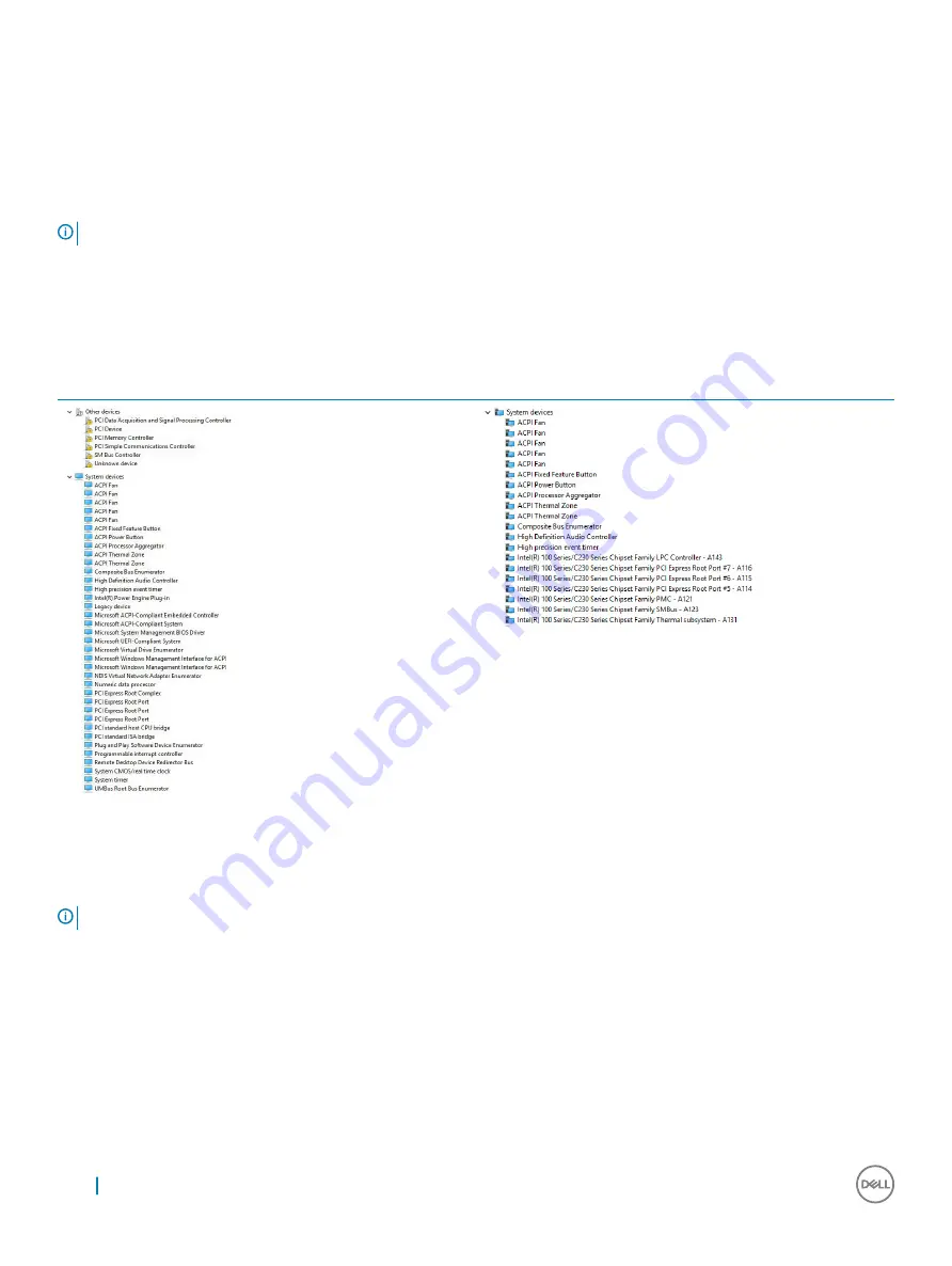
Intel chipset drivers

Verify if the Intel chipset drivers are already installed in the computer.

NOTE: 

Click Start

 > 

Control Panel

 > 

Device Manager

or

In Search the web and Windows, type 

Device Manager

Table 19. Intel chipset drivers

Before installation

After installation

Intel HD Graphics drivers

Verify if the Intel HD Graphics drivers are already installed in the computer.

NOTE: 

Click Start

 > 

Control Panel

 > 

Device Manager.

or

Tap Search the web and Windows and type

 Device Manager

56

Software

Summary of Contents for OptiPlex 5050

Page 1: ...OptiPlex 5050 Small Form Factor Owner s Manual Regulatory Model D11S Regulatory Type D11S002 ...

Page 2: ...amage to hardware or loss of data and tells you how to avoid the problem WARNING A WARNING indicates a potential for property damage personal injury or death 2017 Dell Inc or its subsidiaries All rights reserved Dell EMC and other trademarks are trademarks of Dell Inc or its subsidiaries Other trademarks may be trademarks of their respective owners 2017 02 Rev A00 ...

Page 3: ...alling the coin cell battery 12 Front Bezel 12 Removing bezel 12 Installing the bezel 13 Speaker 13 Removing speaker 13 Installing the speaker 14 Intrusion switch 14 Removing intrusion switch 14 Installing the intrusion switch 15 Storage 15 Removing 2 5 inch drive assembly 15 Removing the 2 5 inch drive from the bracket 17 Installing the 2 5 inch drive into the bracket 18 Installing the 2 5 inch d...

Page 4: ...Optane Memory Module 16 GB 35 Overview 35 Intel OptaneTM Memory Module Driver Requirements 35 M 2 Intel Optane Memory Module 16 GB 35 Product specifications 38 Environmental Conditions 39 Troubleshooting 40 4 Technology and components 41 USB features 41 USB 3 0 USB 3 1 Gen 1 SuperSpeed USB 41 Speed 41 Applications 42 Compatibility 43 HDMI 1 4 43 HDMI 1 4 Features 43 Advantages of HDMI 43 5 System ...

Page 5: ...ostic error messages 59 System error messages 62 8 Technical specifications 63 Processor specifications 63 Memory specifications 64 Video specifications 64 Audio specifications 64 Communication specifications 65 Storage specifications 65 Ports and connectors specifications 66 Power supply specifications 66 Physical dimension specifications 66 Controls and lights specifications 66 Environmental spe...

Page 6: ...Handle components and cards with care Do not touch the components or contacts on a card Hold a card by its edges or by its metal mounting bracket Hold a component such as a processor by its edges not by its pins CAUTION When you disconnect a cable pull on its connector or on its pull tab not on the cable itself Some cables have connectors with locking tabs if you are disconnecting this type of cab...

Page 7: ...ick Start 2 Click Shut Down NOTE Ensure that the computer and all attached devices are turned off If your computer and attached devices did not automatically turn off when you shut down your operating system press and hold the power button for about 6 seconds to turn them off After working inside your computer After you complete any replacement procedure ensure that you connect any external device...

Page 8: ...is document require the following tools Small flat blade screwdriver Phillips 1 screwdriver Small plastic scribe Back cover Removing cover 1 Follow the procedure in Before working inside your computer 2 To release the cover a Slide the blue retention tab to the right to unlock the cover 1 b Slide the cover toward the back of the computer 2 2 8 Removing and installing components ...

Page 9: ...de the cover until it clicks into place 2 Follow the procedure in After working inside your computer Expansion card Removing expansion card 1 Follow the procedure in Before working inside your computer 2 Remove the cover 3 Pull the metal tab to open the expansion card latch Removing and installing components 9 ...

Page 10: ...4 To remove the expansion card a Pull the release tab at the base of the expansion card 1 b Disconnect and lift the expansion card away from the connector 2 10 Removing and installing components ...

Page 11: ...ace 4 Install the cover 5 Follow the procedure in After working inside your computer Coin cell battery Removing coin cell battery 1 Follow the procedure in Before working inside your computer 2 Remove the a cover 3 To remove the coin cell battery a Press the release latch until the coin cell battery pops out 1 b Remove the coin cell battery from the connector on the system board 2 Removing and ins...

Page 12: ...ector until it locks into place 3 Install the a cover 4 Follow the procedure in After working inside your computer Front Bezel Removing bezel 1 Follow the procedure in Before working inside your computer 2 Remove the cover 3 To remove the front bezel a Lift the tabs to release the front bezel from the computer 1 b Remove the front bezel from the computer 2 12 Removing and installing components ...

Page 13: ...After working inside your computer Speaker Removing speaker 1 Follow the procedure in Before working inside your computer 2 Remove the a cover b bezel c 2 5 inch drive assembly d optical drive 3 To remove the speaker a Disconnect the speaker cable from the system board 1 b Press the release tabs and pull the speaker out from the computer 2 3 Removing and installing components 13 ...

Page 14: ... bezel d cover 4 Follow the procedure in After working inside your computer Intrusion switch Removing intrusion switch 1 Follow the procedure in Before working inside your computer 2 Remove the a cover 3 To remove the intrusion switch a Disconnect the intrusion switch cable from the connector on the system board 1 2 b Slide the intrusion switch and lift it away from the computer 3 14 Removing and ...

Page 15: ...the configuration you choose you will have either one 3 5 inch hard drive assembly or two 2 5 inch hard drive assembly Removing 2 5 inch drive assembly 1 Follow the procedure in Before working inside your computer 2 Remove the a cover 3 To remove the 2 5 inch drive assembly a Push the release tabs and disconnect the 2 5 inch drive power cable 1 2 b Disconnect the 2 5 inch drive assembly cables fro...

Page 16: ...4 To remove the drive assembly a Hold and push the release tab 1 b Lift the 2 5 inch drive assembly from the computer 2 16 Removing and installing components ...

Page 17: ...g Inside Your Computer 2 Remove the a cover b 2 5 inch drive assembly 3 To remove the drive a Pull one side of the drive bracket to disengage the pins on the bracket from the slots on the drive 1 b Lift the drive out of the 2 5 inch drive bracket 2 Removing and installing components 17 ...

Page 18: ...5 inch drive assembly 1 Insert the drive assembly into the slot on the computer 2 Connect the power cable to the slot on the drive bracket 3 Install the a cover 4 Follow the procedure in After working inside your computer Optical drive Removing the optical drive 1 Follow the procedure in Before working inside your computer 2 Remove the a cover b bezel c 2 5 inch drive assembly 3 To release the opt...

Page 19: ... Holding the tab disconnect the optical drive cables 2 c Slide and lift the optical drive module away from the computer 3 5 To remove the optical drive a Slide the tab to release the optical drive 1 b Push the optical drive away from the module 2 3 Removing and installing components 19 ...

Page 20: ...optical drive 5 Install the a 2 5 inch drive assembly b bezel c cover 6 Follow the procedure in After working inside your computer M 2 PCIe SSD Removing the M 2 PCIe SSD 1 Follow the procedure in Before working inside your computer 2 Remove the a cover b bezel c 2 5 inch drive assembly d optical drive 3 To remove the M 2 PCIe SSD a Pull the blue tab to release the M 2 PCIe SSD b Disconnect the M 2...

Page 21: ... Optical drive b 2 5 inch drive assembly c bezel d cover 4 Follow the procedure in After working inside your computer Heat sink assembly Removing heat sink assembly 1 Follow the procedure in Before working inside your computer 2 Remove the a cover b bezel c 2 5 inch drive assembly d optical drive Removing and installing components 21 ...

Page 22: ...eat sink assembly onto the processor 2 Tighten the captive screws to secure the heat sink assembly to the system board 3 Connect the heat sink assembly cable to the system board 4 Install the a optical drive b 2 5 inch drive assembly c bezel d cover 5 Follow the procedure in After working inside your computer Processor Removing processor 1 Follow the procedure in Before working inside your compute...

Page 23: ...ign the processor with the socket keys 2 Align the pin 1 indicator of the processor with the triangle on the socket 3 Place the processor on the socket such that the slots on the processor align with the socket keys 4 Close the processor shield by sliding it under the retention screw 5 Lower the socket lever and push it under the tab to lock it 6 Install the a heat sink assembly b optical drive c ...

Page 24: ...ch on the memory module with the tab on the memory module connector 2 Insert the memory module into the memory module socket 3 Press the memory module until the memory module retention tabs click into place 4 Install the a optical drive b 2 5 inch drive assembly c bezel d cover 5 Follow the procedure in After working inside your computer SD card reader Removing the SD card reader 1 Follow the proc...

Page 25: ...ace the SD card reader on the chassis 2 Tighten the screws that secure the SD card reader to the computer 3 Install the a M 2 PCIe SSD b optical drive c 2 5 inch drive assembly d bezel e cover 4 Follow the procedure in After working inside your computer Power supply unit Removing power supply unit PSU 1 Follow the procedure in Before working inside your computer 2 Remove the a cover Removing and i...

Page 26: ... the system board 1 2 b Unroute the power cables from the retention clips on the chassis 3 4 4 To remove the PSU a Disconnect the power cable from the system board 1 2 b Lift the cables away from the computer 3 c Remove the screws that secure the PSU to the computer 4 26 Removing and installing components ...

Page 27: ...5 Press the blue release tab 1 slide the PSU and lift it away from the computer 2 Removing and installing components 27 ...

Page 28: ... 3 Route the PSU cables through the retention clips 4 Connect the power cables to the system board 5 Install the a optical drive b 2 5 inch drive assembly c bezel d cover 6 Follow the procedure in After working inside your computer Power switch Removing power switch 1 Follow the procedure in Before working inside your computer 2 Remove the a cover b bezel 28 Removing and installing components ...

Page 29: ...out from the computer 2 3 Installing the power switch 1 Slide the power switch module into the slot on the chassis until it clicks into place 2 Connect the power switch cable to the connector on the system board 3 Install the a drive assembly b optical drive c bezel d cover 4 Follow the procedure in After working inside your computer Removing and installing components 29 ...

Page 30: ...optical drive e heat sink f processor g expansion card h memory module i M 2 PCIe SSD j SD card reader 3 To remove the I O panel a Remove the screw that secures the I O panel 1 b Slide and push toward the front from the computer 2 4 Disconnect the following cables from the system board a speaker 1 b 2 5 inch drive 2 30 Removing and installing components ...

Page 31: ...ta cable 4 5 Disconnect the following cables and screw from the system board a PSU 1 b hard drive and optical drive caddy stand off screw 2 c PSU 3 d power switch 4 e intrusion switch 5 Removing and installing components 31 ...

Page 32: ...6 To remove the system board a Remove the screws that secure the system board to the computer 1 b Slide and lift the system board away from the computer 2 32 Removing and installing components ...

Page 33: ...tandoffs on the computer 3 Tighten the screws to secure the system board to the computer 4 Route all the cables through the routing clips 5 Align the cables with the pins on connectors on the system board and connect the following cables to the system board a intrusion switch b optical drive c hard drive d PSU e power switch f intrusion switch g speaker 6 Install the a SD card reader b M 2 PCIe SS...

Page 34: ...Slots DIMM1 DIMM2 DIMM3 DIMM4 9 M 2 Slot 3 Connector M 2_SSD 10 Power Switch Connector PWR_SW 11 Media Card Reader Connector CARD_READER 12 SATA2 Connector Black Color SATA2 13 SATA0 Connector Blue Color SATA0 14 ATX Power Connector ATX_SYS 15 HDD and ODD Power Cable Connector SATA_PWR 16 Service Mode jumper SERVICE_MODE 17 Clear Password Jumper PASSWORD_CLR 18 Clear CMOS Jumper CMOS_CLR 19 Intern...

Page 35: ...h NVMe interface Uses Intel s revolutionary new storage technology 3D XpointTM memory media Ultra low latency exceptional responsiveness Performance saturation at queue depth of 4 and lower Very high endurance capabilities Intel OptaneTM Memory Module Driver Requirements The following table describes the driver requirements for the Intel OptaneTM memory system acceleration us a component of Intel ...

Page 36: ...b Place the thermal pad on the SSD slot and remove the white adhesive tape c Place the M 2 Intel optane memory module into the slot on the thermal pad 36 M 2 Intel Optane Memory Module 16 GB ...

Page 37: ...r If the system is shipped with self locking spacer press to lock the M 2 Intel optane to secure on the computer 4 To remove the expansion card a Pull the release tab at the base of the expansion card 1 b Disconnect and lift the expansion card away from the connector 2 M 2 Intel Optane Memory Module 16 GB 37 ...

Page 38: ...D4 4HB Random Write 240K IOPs Latency average sequential Read 8 25 µ Write 30 µ Components Intel 3D XPoint Memory Media Intel Controller and Firmware PCIe 3 0x2 with NVMe Interface Intel Rapid Storage Technology 15 2 or later Operating System Support Windows 10 64 bit Supported Platforms 7th generation or newer Intel Core processor based platforms Power 3 3V Supply Rail 38 M 2 Intel Optane Memory ...

Page 39: ...z Non Operating 3 13 GRMS 5 800Hz Altitude Simulated Operating 1 000 ft to 10 000 ft Non Operating 1 000 ft to 40 000 ft Product Ecological Compliance RoHS Reliability Uncorrectable Bit Error Rate UBER 1 sector per 1015 bits read Mean Time Between Failure MTBF 1 6 million hours Environmental Conditions Table 2 Temperature Shock Vibration Temperature M 2 2280 form factor Operating1 Non operating 2 ...

Page 40: ...ce is mounted securely with the input vibration applied to the drive mounting screws Stimulus may be applied in the X Y or Z axis Vibration specificities is measured using RMS value Troubleshooting 1 The Intel Optane Memory model name NVME INTEL MEMPEK1W01 in Device Manager does not match in the Intel Rapid Storage Technology user interface it only shows a part of the serial number information Thi...

Page 41: ...on devices sold and yet the need for more speed grows by ever faster computing hardware and ever greater bandwidth demands The USB 3 0 USB 3 1 Gen 1 finally has the answer to the consumers demands with a theoretically 10 times faster than its predecessor In a nutshell USB 3 1 Gen 1 features are as follows Higher transfer rates up to 5 Gbps Increased maximum bus power and increased device current d...

Page 42: ... actual real world maximum Similarly USB 3 0 USB 3 1 Gen 1 connections will never achieve 4 8Gbps We will likely see a real world maximum rate of 400MB s with overheads At this speed USB 3 0 USB 3 1 Gen 1 is a 10x improvement over USB 2 0 Applications USB 3 0 USB 3 1 Gen 1 opens up the laneways and provides more headroom for devices to deliver a better overall experience Where USB video was barely...

Page 43: ...D player or A V receiver and a compatible digital audio and or video monitor such as a digital TV DTV The intended applications for HDMI TVs and DVD players The primary advantage is cable reduction and content protection provisions HDMI supports standard enhanced or high definition video plus multichannel digital audio on a single cable NOTE The HDMI 1 4 will provide 5 1 channel audio support HDMI...

Page 44: ...DMI combines video and multichannel audio into a single cable eliminating the cost complexity and confusion of multiple cables currently used in A V systems HDMI supports communication between the video source such as a DVD player and the DTV enabling new functionality 44 Technology and components ...

Page 45: ...example optical drive or hard drive During the Power on Self Test POST when the Dell logo appears you can Access System Setup by pressing F2 key Bring up the one time boot menu by pressing F12 key The one time boot menu displays the devices that you can boot from including the diagnostic option The boot menu options are Removable Drive if available STXXXX Drive NOTE XXX denotes the SATA drive numb...

Page 46: ... a basic level of security for the data on your computer CAUTION Anyone can access the data stored on your computer if it is not locked and left unattended NOTE Your computer is shipped with the system and setup password feature disabled Assigning a system password and setup password You can assign a new System Password only when the status is in Not Set To enter the system setup press F2 immediat...

Page 47: ...ding on the computer and its installed devices the items listed in this section may or may not appear Table 5 General Option Description System Information Displays the following information System Information Displays BIOS Version Service Tag Asset Tag Ownership Tag Ownership Date Manufacture Date and the Express Service Code Memory Information Displays Memory Installed Memory Available Memory Sp...

Page 48: ...A 4 M 2 PCIe SSD 0 Smart Reporting This field controls whether hard drive errors for integrated drives are reported during system startup The Enable Smart Reporting option is disabled by default USB Configuration Allows you to enable or disable the integrated USB controller for Enable Boot Support Enable Front USB Ports Enable Rear USB Ports Front USB Configuration Allows you to enable or disable ...

Page 49: ...nternal HDD password when they are set This option is selected by default Reboot Bypass Bypass the password prompts on Restarts warm boots NOTE The system will always prompt for the system and internal HDD passwords when powered on from the off state a cold boot Also the system will always prompt for passwords on any module bay HDDs that may be present Password Change This option lets you determin...

Page 50: ... the hotkey Admin Setup Lockout Allows you to enable or disable the option to enter Setup when an Administrative password is set This option is not set by default Table 9 Secure Boot Option Description Secure Boot Enable Allows you to enable or disable Secure Boot feature Disable Enable Expert key Management Allows you to manipulate the security key databases only if the system is in Custom Mode T...

Page 51: ...llows you to enable or disable additional processor sleep states The option C states is selected by default Limited CPUID Value Allows you to limit the maximum value of the processor standard CPUID function The option Enable CPUID Limit is not selected by default Intel TurboBoost Allows you to enable or disable the Intel TurboBoost mode of the processor This option is enabled by default Table 12 P...

Page 52: ... up and immediately boot to PXE WLAN Only Allows the system to be powered on by special WLAN signals This option is Disabled by default Block Sleep Allows you to block entering to sleep S3 state in OS environment This option is disabled by default Intel Ready Mode Allows you to enable the capability of Intel Ready Mode Technology This option is disabled by default Table 13 POST Behavior Option Des...

Page 53: ...g of the system firmware to the previous versions This option is enabled by default NOTE If this option is not selected the flashing of the system firmware to the previous versions is blocked Data Wipe Allows you to securely erase the data from all the available internal storages such as HDD SSD mSATA and eMMC The option Wipe on Next Boot is disabled by default BIOS recovery Allows you to recover ...

Page 54: ...ate the BIOS from 1 0 to 7 0 then install version 4 0 first and then install version 7 0 Enabling smart power on To enable Smart Power On and the ability to wake a system from S3 S4 and S5 sleep states with a move of a mouse or press of a key on the keyboard perform these steps 1 Make sure the following BIOS settings under Power Management setup option are set as mentioned here USB Wake Support as...

Page 55: ...auto detect feature or manually browse for your computer model 4 Click Drivers and Downloads 5 Select the operating system installed on your computer 6 Scroll down the page and select the driver to install 7 Click Download File to download the driver for your computer 8 Navigate to the folder where you saved the driver file after the download is complete 9 Double click the driver file icon and fol...

Page 56: ...ipset drivers Verify if the Intel chipset drivers are already installed in the computer NOTE Click Start Control Panel Device Manager or In Search the web and Windows type Device Manager Table 19 Intel chipset drivers Before installation After installation Intel HD Graphics drivers Verify if the Intel HD Graphics drivers are already installed in the computer NOTE Click Start Control Panel Device M...

Page 57: ...Table 20 Intel HD Graphics drivers Before installation After installation Software 57 ...

Page 58: ...nd power extension cables to verify that the computer turns on properly Ensure the electrical outlet is working by testing it with another device such as a lamp Steady blinking amber Computer fails to complete POST or processor failure Remove and reinstall any cards Remove and reinstall the graphics card if applicable Ensure the power cable is connected to the system board and processor Blinking w...

Page 59: ...ouchpad or external mouse may be faulty For an external mouse check the cable connection Enable the Pointing Device option in the System Setup program BAD COMMAND OR FILE NAME Ensure that you have spelled the command correctly put spaces in the proper place and used the correct path name CACHE DISABLED DUE TO FAILURE The primary cache internal to the microprocessor has failed Contact Dell CD DRIVE...

Page 60: ...he hard drive and boot the computer from an optical drive Then shut down the computer reinstall the hard drive and restart the computer If the problem persists try another drive Run the Hard Disk Drive tests in Dell Diagnostics HARD DISK DRIVE READ FAILURE The hard drive may be defective Shut down the computer remove the hard drive and boot the computer from an optical Then shut down the computer ...

Page 61: ...is installed properly seated and partitioned as a boot device NO BOOT SECTOR ON HARD DRIVE The operating system may be corrupted Contact Dell NO TIMER TICK INTERRUPT A chip on the system board may be malfunctioning Run the System Set tests in Dell Diagnostics NOT ENOUGH MEMORY OR RESOURCES EXIT SOME PROGRAMS AND TRY AGAIN You have too many programs open Close all windows and open the program that ...

Page 62: ...se note this checkpoint and contact Dell Technical Support The computer failed to complete the boot routine three consecutive times for the same error CMOS checksum error RTC is reset BIOS Setup default has been loaded CPU fan failure CPU fan has failed System fan failure System fan has failed Hard disk drive failure Possible hard disk drive failure during POST Keyboard failure Keyboard failure or...

Page 63: ... 5050 systems are shipped with Intel 6th generation and 7th generation core processor technology NOTE The clock speed and performance varies depending on the workload and other variables Total cache up to 8 MB cache depending on processor type Feature Specification Processor type 6th Generation Intel Core i3 6100 6th Generation Intel Core i5 6400 6th Generation Intel Core i5 6500 6th Generation In...

Page 64: ...GB 1x 8 GB 16 GB 2x 8 GB 32 GB 4x 8 GB 64 GB 4x 16 GB Video specifications Feature Specification Video Controller Integrated For Intel 7th generation processors Intel HD 630 Graphics with 7th Generation Core i3 i5 i7 CPU GPU combo Intel HD 610 Graphics with 7th Generation Pentium CPU GPU combo For Intel 6th generation processors Intel HD 530 with 6th Generation Core i3 i5 i7 CPU GPU combo Intel HD...

Page 65: ...tions 2 5 500 GB SATA3 5400 RPM HDD 2 5 500 GB SATA3 7200 RPM HDD 2 5 500 GB SATA3 Solid State HYBRID HDD W 8GB FLASH 2 5 500 GB SATA3 7200 RPM SELF ENCRYPTING DRIVE OPAL v2 0 compliant 2 5 1 TB SATA3 7200RPM HDD 2 5 1 TB SATA3 Solid State HYBRID HDD W 8GB FLASH 2 5 2 TB SATA3 5400 RPM HDD 2 5 256 GB SOLID STATE DRIVE Class 20 2 5 512 GB SOLID STATE DRIVE Class 20 3 5 inch hard drive options 3 5 5...

Page 66: ... PS 2 Two Power supply specifications Feature Specification Type 180 W Frequency 47 Hz 63 Hz Voltage 90 VAC 264 VAC Input current 3 A 1 5 A Coin cell battery 3 V CR2032 lithium coin cell Physical dimension specifications Feature Specification Height 290 06 mm 11 42 inches Width 92 6 mm 3 65 inches Depth 292 mm 11 50 inches Weight 5 26 kg 11 57 lb Controls and lights specifications Feature Specific...

Page 67: ...is present Power supply diagnostic light Green light The power supply is turned on and is functional The power cable must be connected to the power connector at the back of the computer and the electrical outlet Environmental specifications Temperature Specifications Operating 0 C to 35 C 32 F to 95 F Storage 40 C to 65 C 40 F to 149 F Relative humidity maximum Specifications Operating 10 to 90 no...

Page 68: ... service options Availability varies by country and product and some services may not be available in your area To contact Dell for sales technical support or customer service issues 1 Go to Dell com support 2 Select your support category 3 Verify your country or region in the Choose a Country Region drop down list at the bottom of the page 4 Select the appropriate service or support link based on...

Reviews: