background image

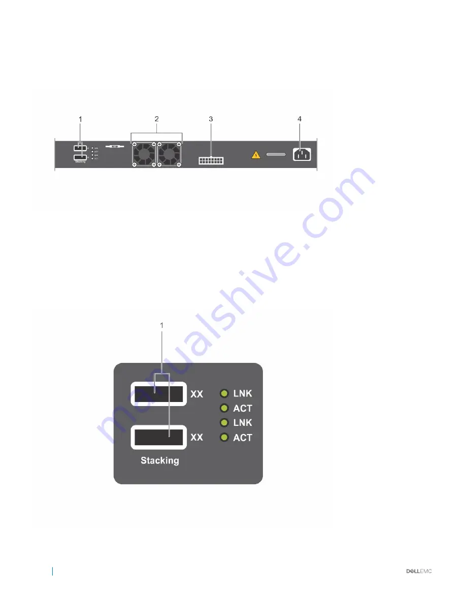
N20xx Series PSU-Side

The following image shows the PSU-side of the N20xx switches.

Figure 4. N20xx PSU-Side

1

Mini-SAS stacking ports

2

Fan Vents

3

To DC Power Source (Optional)

4

AC Power Receptacle

The term mini-SAS refers to the stacking port cable connections. For information about using the mini-SAS ports to connect switches, see 
the 

Stacking Multiple N20xx Switches

 section.

Figure 5. N2048 Mini-SAS Stacking Ports Close-up

8

N20xx Series Overview

Summary of Contents for N20xx Series

Page 1: ...Dell Networking N20xx and N30xx Series Switch Installation Guide Regulatory Model N20xx N30xx ...

Page 2: ... to hardware or loss of data and tells you how to avoid the problem WARNING A WARNING indicates a potential for property damage personal injury or death Copyright 2016 Dell Inc or its subsidiaries All rights reserved Dell EMC and other trademarks are trademarks of Dell Inc or its subsidiaries Other trademarks may be trademarks of their respective owners 2016 12 Rev A00 ...

Page 3: ...he Dell Networking OS Conversion Guide for the N20xx N30xx Series For complete installation configuration and update information see the following documents at www dell com support Table 1 N20xx N30xx Documentation Information Documentation Software configuration Dell Networking Configuration Guide for the C9000 Series for Dell Networking OS 9 11 0 0 or later Dell Networking N Series User Guide fo...

Page 4: ...models are 1U rack mountable switches with the following physical dimensions 440 0 x 257 0 x 43 5 mm W x D x H 17 3 x 10 1 x 1 7 inches W x D x H All N20xx PoE models are 1U rack mountable switches with the following physical dimensions 440 0 x 387 0 x 43 5 mm W x D x H 17 3 x 15 2 x 1 7 inches W x D x H Other characteristics PSU handle length 1 25 inches Stacking cable length 2 5 inches N20xx Ser...

Page 5: ...ort 2 USB Port 3 Reset Button 4 SFP Ports The N20xx I O side has status light emitting diodes LEDs for overtemperature alarm internal power and status on the top row The bottom row of the status LEDs display the stack master redundant power supply RPS status and fan alarm status N20xx Series Overview 5 ...

Page 6: ...8 Gigabit Ethernet 10BASE T 100BASE TX 1000BASE T RJ 45 ports that support autonegotiation for speed flow control and duplex The N2048 N2048P support two SFP 10G ports Dell qualified SFP transceivers are sold separately The front panel switch ports have the following characteristics The switch automatically detects the difference between crossed and straight through cables on RJ 45 ports and autom...

Page 7: ...iles and images from one switch to other switches in the network The USB port does not support any other type of USB device Reset Button The reset button is accessed through the pinhole and allows you to perform a hard reset on the switch To use the reset button insert an unbent paper clip or similar tool into the pinhole When the switch completes the boot process after the reset it resumes operat...

Page 8: ...ing ports 2 Fan Vents 3 To DC Power Source Optional 4 AC Power Receptacle The term mini SAS refers to the stacking port cable connections For information about using the mini SAS ports to connect switches see the Stacking Multiple N20xx Switches section Figure 5 N2048 Mini SAS Stacking Ports Close up 8 N20xx Series Overview ...

Page 9: ...PoE devices 1800W NOTE PoE power is dynamically allocated Not all ports require the full PoE power CAUTION Remove the power cable from the power supplies prior to removing the power supply module itself You must not connect power prior to insertion in the chassis Ventilation System Two fans cool the N20xx switches N20xx Model Summary Table 2 N20xx Model Summary Marketing Model Name Description Pow...

Page 10: ...lative Humidity The operating relative humidity is 8 to 85 noncondensing with a maximum humidity gradation of 10 per hour Topics Unpacking the N20xx Switch Rack Mounting an N20xx Switch Stacking on N20xx Series Switches Unpacking the N20xx Switch Package Contents When unpacking each switch make sure that the following items are included One Dell Networking switch One RJ 45 to DB 9 female cable One...

Page 11: ... the right rack mount bracket with the holes on the right side facing you of the switch 2 Secure the bracket item 3 to the chassis by tightening the screws item 2 provided with the mount bracket Figure 6 Attaching Mount Brackets to the N20xx 3 Repeat Steps 1 and 2 to attach the left rack mount bracket on the device 4 Mount the switch into a 48 26 cm 19 inch rack Align the holes on each bracket fla...

Page 12: ...s how to stack multiple N20xx series switches Stacking Multiple N20xx Switches on Dell Networking OS 6 3 0 16 If you are using Dell Networking OS version 6 3 0 16 you can stack up to 12 switches using the mini SAS ports located on the rear of the switch N20xx switches support stacking only with other N20xx series switches When you connect multiple switches together through the stack ports they ope...

Page 13: ...r unit NOTE Although individual stack members do not require a separate uplink to a parent C9010 Dell Networking recommends connecting more than one stack unit to the C9010 for redundancy A stack unit uses the stacking connection to the master PE for its C9010 uplink For more information see the Connecting to a C9010 Switch section Creating a Switch Stack Create a stack by connecting adjacent unit...

Page 14: ...uration for the stack The Standby unit is automatically selected in the stack however you can use the CLI to select a different stack member as Standby For more information see the User s Configuration Guide or the CLI Reference Guide Stacking Standby on Dell Networking OS 9 11 0 0 If the system runs Dell Networking OS version 9 11 0 0 the system supports a Standby or backup unit that assumes the ...

Page 15: ...ded with an RJ 45 connector for the console port and DB 9 connector for the terminal To connect a terminal to the switch console port 1 Connect the DB 9 connector on the serial cable to the terminal or computer running VT100 terminal emulation software 2 Configure the terminal emulation software as follows a Select the appropriate serial port for example COM 1 to connect to the console b Set the d...

Page 16: ...h console port is connected to a VT100 terminal or VT100 terminal emulator using the RJ 45 to DB 9 female cable 2 Using a 5 foot 1 5 meter standard power cable with safety ground connected connect the power cable to the AC main receptacle on the PSU side 3 Connect the power cable to a grounded AC outlet 4 If you are using a redundant or external DC power supply such as the Dell Networking RPS720 o...

Page 17: ...ion about the Boot menu functions see the CLI Reference Guide Initial Configuration This section describes how to perform the initial configuration on your system Perform the Initial Configuration on Dell Networking OS 6 3 0 16 The initial configuration procedure is based on the following assumptions The Dell Networking switch was never configured before The Dell Networking switch booted successfu...

Page 18: ...ation guide describes how to use the Dell Easy Setup Wizard for initial switch configuration The wizard sets up the following configuration on the switch Establishes the initial privileged user account with a valid password The wizard configures one privileged user account during the setup Enables CLI login and HTTP access to use the local authentication setting only Sets up the IP address for the...

Page 19: ...ration before or after you install and power on the PE To provision an N20xx system start from the C9010 console and enter the following commands If you enter the commands before you install the N20xx system with a parent C9010 the preconfigured software settings download to the N20xx system when you attach it to a C9010 port and power it up NOTE Although you can provision an N20xx system after yo...

Page 20: ...r Dell conf feature extended bridge Dell conf pe provision 2 Dell conf pe 2 stack unit 0 type n3048p Dell conf pe 2 cascade interface tengigabitethernet 0 1 2 Dell conf pe 2 exit Dell conf interface range tengigabitethernet 0 1 2 Dell conf if te 0 1 2 no shutdown Dell conf if end Dell show pe brief Port Extenders Information PE id Status Stack size Type System MAC 2 online 1 N2048P 34 17 eb 00 bb ...

Page 21: ...igure L2 software features on the N20xx system from the C9010 console CLI including LLDP 802 1x LACP loop detection and BPDU Guard No other L2 protocols are supported IP address and L3 protocol configuration on N20xx ports are not supported For detailed information see the Dell Networking Configuration Guide for C9000 Series Switches When the N20xx system is online you can enter the connect pe pe ...

Page 22: ...ins information about device characteristics and modular hardware configurations for the N30xx Series switches All N30xx models are 1U rack mountable switches with the following physical dimensions 434 0 x 407 0 x 43 5 mm W x D x H 17 1 x 16 0 x 1 7 inches W x D x H N30xx Series I O Side The following images show the I O sides of the switch models in the N30xx Series Figure 11 N3024F with 24 10 10...

Page 23: ... ports 1 Console port 2 USB port 3 SFP Ports 4 Combo Ports 5 10 100 1000BASE T Auto sensing Full Duplex RJ 45 Ports The combo ports are SFP on the N30xx series and 1000BaseT on the N3024F switch Figure 13 N30xx Close up 1 Console port 2 Out of Band Management Port 3 USB port 4 Reset Button 5 SFP Ports N30xx Series Overview 23 ...

Page 24: ...ex mode 10 100 1000 Mbps speeds on standard Category 5 UTP cable SFP ports support SFP transceivers and SFP copper twin ax technology plus SFP transceivers operating at 1G The N3024P N3048P I O side ports support PoE 15 4W and PoE 30W Console Port The console port provides serial communication capabilities which allows communication using RS 232 protocol The serial port provides a direct connectio...

Page 25: ...side contains LEDs that indicate the status of port links power supplies fans stacking and the overall system status For information about the status that the LEDs indicate see the User s Configuration Guide Stack Master LED and Stack Number Display When a switch within a stack is the master unit the stack master LED which is labeled M is solid green If the M LED is off the stack member is not the...

Page 26: ...ni SAS stacking ports 4 Fan Vents Figure 16 N3048 Mini SAS Stacking Ports Close up 1 Mini SAS stacking ports The term mini SAS refers to the stacking port cable connections For information about using the mini SAS ports to connect switches see the Stacking Multiple N30xx Switches section 26 N30xx Series Overview ...

Page 27: ...he N3024P switch comes with a single 715 watt power supply the default configuration and supports either one or two 1100 watt supplies For the N3048P switch an 1100 watt power supply is the default configuration A single 1100 watt power supply can feed up to 24 PoE devices at full PoE power 950W Dual equipped switches feed up to 48 PoE devices at full PoE power 1800W as well as provide power suppl...

Page 28: ...x1G combo 2x10G SFP 2x Stacking 1x Modular Bay N 1 Redundant Pluggable PSUs 24x PoE ports 12 UPoE Capable Ports 1x Removable Fan Module 1100W 715W E06W E06W001 N3048 48x1G 2x1G combo 2x10G SFP 2x Stacking 1x Modular Bay N 1 Redundant Pluggable PSUs 1x Removable Fan Module 200W E07W E07W002 N3048P 48x1G 2x1G combo 2x10G SFP 2x Stacking 1x Modular Bay N 1 Redundant Pluggable PSUs 48x PoE ports 12 UP...

Page 29: ...85 ft above 900m 2955 ft Relative Humidity The operating relative humidity is 8 to 85 noncondensing with a maximum humidity gradation of 10 per hour Topics Unpacking the N30xx Switch Rack Mounting an N30xx Switch Stacking on N30xx Series Switches Unpacking the N30xx Switch Package Contents When unpacking each switch make sure that the following items are included One Dell Networking switch One RJ ...

Page 30: ...ack environment may be greater than room ambient Use care not to exceed the 45 degrees C maximum ambient temperature of the switch Reduced air flow Install the equipment in the rack so that the amount of airflow required for safe operation of the equipment is not compromised Reliable earthing Maintain reliable earthing of rack mounted equipment Pay particular attention to supply connections other ...

Page 31: ...ws from each front flange ear on the switch side of the rail and remove each casting Retain the castings for future rack requirements You need not remove the rear flange castings 2 Attach one rail to the front post flange with two user supplied screws See item 2 3 Slide the plunger bracket forward against the vertical post and secure the plunger bracket to the post flange with two user supplied sc...

Page 32: ...edure for the second rail Figure 19 2 Post Center Mount Configuration 4 Post Threaded Configuration To install the Dell ReadyRails system using the four post threaded configuration follow these steps 1 For this configuration remove the flange ear castings from each end of the ReadyRails assemblies Use a Torx driver to remove the two screws from each flange ear and remove each casting See item 1 of...

Page 33: ...For the 1U two post flush and center configurations slide the system into the rails in the same manner as the four post configurations Installing a 1U Front Rack You must configure the rails that are attached to the system 1 Attach the switch rails inner chassis members to the N30xx system Item 3 in the following illustration shows the detail for the front standoff with the locking tab N30xx Serie...

Page 34: ... the previously mounted ReadyRails and slide the switch in until it is flush with front of rack About 3 inches before you fully insert your system the rail locking feature engages to keep the switch from inadvertently sliding out of the rack and falling NOTE Do not the use the mounted ReadyRails as a shelf or a workplace 34 N30xx Series Installation ...

Page 35: ...ce must be able to support the weight of the switch and the switch cables The switch is supplied with four self adhesive rubber pads 1 Attach the self adhesive rubber pads on each location marked on the bottom of the switch 2 Set the switch on a flat surface Make sure that it has proper ventilation by leaving 5 cm 2 inches on each side and 13 cm 5 inches at the back Stacking on N30xx Series Switch...

Page 36: ...nstalling a stack assemble and cable the stack before powering it up When you power up a stack for the first time the units receive the provisioned configuration from the parent C9010 A Stack Master unit is elected based on the highest MAC address or highest provisioned priority The master unit may occupy any location in the stack The Stack Master LED on the I O side lights on the master unit NOTE...

Page 37: ...he Standby unit initializes the control plane and enables all other stack units with the current configuration The Standby unit maintains a synchronized copy of the running configuration for the stack The Standby unit is automatically selected in the stack however you can use the CLI to select a different stack member as Standby For more information see the User s Configuration Guide or the CLI Re...

Page 38: ...e stack you can use the CLI on the C9010 or the N20xx N30xx series system console to manually configure a different stack member as Standby For more information see the Dell Networking Configuration Guide for C9000 Series Switches 38 N30xx Series Installation ...

Page 39: ...l port running VT100 terminal emulation software such as Microsoft HyperTerminal A serial cable provided with an RJ 45 connector for the console port and DB 9 connector for the terminal To connect a terminal to the switch console port 1 Connect the DB 9 connector on the serial cable to the terminal or computer running VT100 terminal emulation software 2 Configure the terminal emulation software as...

Page 40: ...es that connect to or support the switch The N30xx switches have two FRU power supplies for redundant or load sharing operation AC and DC Power Connection 1 Connect the switch console port to a VT100 terminal or VT100 terminal emulator using the RJ 45 to DB 9 female cable 2 Using a 5 foot 1 5 meter standard power cable with safety ground connected connect the power cable to the AC main receptacle ...

Page 41: ...s section describes how to perform the initial configuration on your system Performing the Initial Configuration on Dell Networking OS 6 3 0 16 The following initial configuration procedure is based on the following assumptions The Dell Networking switch was never configured before The Dell Networking switch booted successfully The Dell Networking switch runs Dell Networking OS version 6 3 0 16 Th...

Page 42: ...izard prompt within 60 seconds the switch enters CLI mode You must reset the switch with an empty startup configuration to rerun the Dell Easy Setup Wizard For more information about performing the initial configuration by using the CLI see the CLI Reference Guide This installation guide shows how to use the Dell Easy Setup Wizard for initial switch configuration The wizard sets up the following c...

Page 43: ...initial switch configuration and gets you up and running as quickly as possible You can skip the setup wizard and enter CLI mode to manually configure the switch You must respond to the next question to run the setup wizard within 60 seconds otherwise the system will continue with normal operation using the default system configuration Note You can exit the setup wizard at any point by entering ct...

Page 44: ...ep 3 Next IP addresses are set up on the OOB Out Of Band Interface and or the VLAN 1 routing interface You can use these IP addresses to access the CLI Web interface or SNMP interface of the switch To access the switch through any Management Interface you can Set up the IP address for the Management Interface Set up the default gateway if IP address is manually configured on both routing and OOB i...

Page 45: ...owser For remote management access to the CLI enter the VLAN 1 management interface IP address into a Telnet or SSH client Alternatively you can continue to use the console port for local CLI access to the switch Your N30xx switch supports basic switching features such as VLANs and spanning tree protocol The N30xx switches also support advanced Layer 3 features such as dynamic routing and multicas...

Page 46: ...0 to 7 The default value is 0 unit type is a stack unit type 4 Provisioning an N30xx system automatically creates a link aggregation group LAG on the C9010 The C9010 LAG member ports are the cascade ports configured for the PE with the cascade interface command The cascade ports must be operationally up no shutdown command and have a default port configuration with no L2 and L3 configuration The p...

Page 47: ...e 0 2 A Dynamically Discovered Cascade Ports None Cascade LAG Po 258 Up Stack id Status Reason Type UnitMac No of Ports 0 online N3048P 34 17 eb 00 bb 11 48 NOTE In the User Configured Cascade Ports field A active indicates that a C9010 port is up no shutdown and configured as a cascade port I inactive indicates that a port is down and configured as a cascade port Dell show interface port channel ...

Reviews: