background image

12

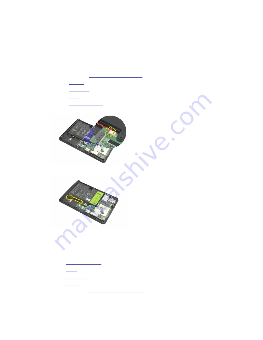
Removing The Coin-Cell Battery

1.

Follow the procedures in 

Before Working On Your Computer

.

2.

Remove the 

label door

.

3.

Remove the 

bottom cover

.

4.

Remove the 

battery

.

5.

Remove the 

Internal Storage Drive

.

6.

Disconnect the coin-cell battery cable.

7.

Release the coin-cell battery cable and remove the coin-cell battery from the computer.

Installing The Coin-Cell Battery

1.

Place the coin-cell battery in its compartment and route the coin-cell battery cable.

2.

Tighten the screws that secure the internal storage device connection.

3.

Install the 

internal storage device

.

4.

Install the 

battery

.

5.

Install the 

bottom cover

.

6.

Install the 

label door

.

7.

Follow the procedures in 

After Working Inside Your Computer

.

35

Summary of Contents for Latitude Slate

Page 1: ...Dell Latitude ST Owner s Manual Regulatory Model T02G Regulatory Type T02G001 ...

Page 2: ...on are trademarks of Advanced Micro Devices Inc Microsoft Windows Windows Server Internet Explorer MS DOS Windows Vista and Active Directory are either trademarks or registered trademarks of Microsoft Corporation in the United States and or other countries Red Hat and Red Hat Enterprise Linux are registered trademarks of Red Hat Inc in the United States and or other countries Novell and SUSE are r...

Page 3: ...ry and Pen Tip 11 Electronic Pen Usage 11 Using the Pen as a Mouse 11 Using the Pen as a Pen 11 Tablet PC Input Panel 12 Working With Files 12 Entering Text 12 Pen Flicks 13 Touch Usage 14 Docking Station 15 3 Removing The SD Memory Card 17 Installing The SD Memory Card 17 4 Removing The Digitizer Pen 19 Installing The Digitizer Pen 19 5 Removing The Label Door 21 Installing The Label Door 21 6 Re...

Page 4: ...ttery 35 13 Removing The Speaker 37 Installing The Speaker 38 14 Removing The Middle Frame Assembly 39 Installing The Middle Frame Assembly 40 15 Removing The Camera 41 Installing The Camera 42 16 Removing The Input Output I O Board 43 Installing The Input Output I O Board 44 17 Removing The Docking Board 45 Installing The Docking Board 46 18 Removing The System Board 47 Installing The System Boar...

Page 5: ... ePSA Diagnostic Utility 55 Beep Codes 57 LED Error Codes 57 N trig Digitizer Troubleshooting 58 Installation IssuesTroubleshooting Steps 58 Performance issuesTroubleshooting Steps 58 Performance issuesTroubleshooting Steps 59 22 Technical Specifications 61 23 Contacting Dell 65 ...

Page 6: ...6 ...

Page 7: ...ap or by periodically touching an unpainted metal surface such as a connector on the back of the computer CAUTION Handle components and cards with care Do not touch the components or contacts on a card Hold a card by its edges or by its metal mounting bracket Hold a component such as a processor by its edges not by its pins CAUTION When you disconnect a cable pull on its connector or on its pull t...

Page 8: ...ystem 2 Ensure that the computer and all attached devices are turned off If your computer and attached devices did not automatically turn off when you shut down your operating system press and hold the power button for about 4 seconds to turn them off After Working Inside Your Computer After you complete any replacement procedure ensure you connect any external devices cards and cables before turn...

Page 9: ...ned to be durable with the rubberized bumper that helps protect against accidental drops while Corning Gorilla Glass helps ensure that your screen can withstand the unexpected The Dell Latitude ST is built to be thin and light to match the mobility needs of executives sales managers doctors and students alike This allows the product to function as a primary system during short business trips sales...

Page 10: ...rom the coil is picked up by the stylus and triggers the stylus to transmit an electric field The transmitted electric field is sensed by a matrix of conductive lines on the slate The accurate stylus position is determined using the low amplitude signals received on the vertical and horizontal conductors Thus an appropriate signal is transferred to the digitizer s on board processor Pen Informatio...

Page 11: ...se You can use the pen the same way you use a mouse or touch pad with a notebook computer Holding the pen near the display makes a small cursor appear Moving the pen moves the cursor The following table describes how to use the pen Table 2 Electrostatic Pen Usage Appearance Action Function Gently tap the pen tip on the screen of your Tablet PC Same as a single click on a mouse Gently tap the pen t...

Page 12: ... you tap it the Input Panel opens at the same horizontal location on the screen that the tab appears Working With Files You can open delete or move many files or folders at one time by selecting multiple items from a list Using a tablet pen hover over one item at a time and select the check box that appears to the left of each item To turn check boxes on 1 Open Control Panel 2 Go to Folder options...

Page 13: ...en or finger The writing pad and the character pad have a number pad a symbol pad and web quick keys to help you quickly and accurately enter these types of text These quick keys are hidden when you start to write but appear after you insert or delete your writing By default The Input Panel automatically switches to the touch keyboard when you place the insertion point in a box for entering a pass...

Page 14: ...ointer floats beneath your finger The touch pointer has left and right mouse buttons that you can tap with your finger You use the area beneath the buttons to drag the touch pointer To show the touch pointer go to Start Control Panel Pen and Touch and clicking on the Touch tab Then at the Touch Pointer section check the option Show the touch pointer when I m interacting with items on the screen 14...

Page 15: ... Station The docking station is designed for Latitude ST The docking station can be purchased separately from dell com For more information see the docking station setup guide available on support dell com 15 ...

Page 16: ...ng Station Front View 1 Dock Connector 2 Power LED Figure 2 Docking Station Back View 1 AC Adapter Connector 2 USB 2 0 Connector 1 3 USB 2 0 Connector 2 4 Network Connector RJ45 5 HDMI Connector 6 Audio Connector 16 ...

Page 17: ...mputer 2 Press in on the SD memory card to release it from the computer 3 Slide the SD memory card out of the computer Installing The SD Memory Card 1 Push the memory card into the compartment until it clicks into place 2 Follow the procedures in After Working Inside Your Computer 17 ...

Page 18: ...18 ...

Page 19: ...mputer 2 Press in on the digitizer pen to release it from the computer 3 Pull the digitizer pen out of the computer Installing The Digitizer Pen 1 Push the digitizer pen into the compartment until it clicks into place 2 Follow the procedures in After Working Inside Your Computer 19 ...

Page 20: ...20 ...

Page 21: ...es the label door 3 Lift up the label door diagonally and remove it from the computer Installing The Label Door 1 Place the label door diagonally and align it with the securing clips on the edges 2 Push the edges of the label door until it clicks into place 3 Follow the procedures in After Working Inside Your Computer 21 ...

Page 22: ...22 ...

Page 23: ...ve the label door 3 Slide the SIM card holder to unlock the SIM card slot 4 Flip the SIM card holder in an upward direction 5 Pull the SIM card out of the SIM card holder and remove it from the computer NOTE Close the SIM card holder after the SIM card has been removed from the computer 23 ...

Page 24: ...Installing The SIM Card 1 Push the SIM card into the SIM card slot until it clicks into place 2 Install the label door 3 Follow the procedures in After Working Inside Your Computer 24 ...

Page 25: ...nd the dummy SD card to prevent any damage to the computer 3 Remove the screws that secure the bottom cover to the computer 4 Press on the latch to release the top section of the bottom cover 5 Pry and release the tabs that secure the bottom cover by following the arrow sequence in the diagram 6 Remove the bottom cover from the computer 25 ...

Page 26: ...over to the computer 2 Push the edges of the bottom cover into the securing clips until they are fully engaged 3 Tighten the screws that secure the bottom cover 4 Install the label door 5 Follow the procedures in After Working Inside Your Computer 26 ...

Page 27: ...cedures in Before Working On Your Computer 2 Remove the label door 3 Remove the bottom cover 4 Disconnect the battery cable 5 Remove the screws that secure the battery to the computer 6 Lift up the battery and remove it from the computer 27 ...

Page 28: ...e the battery in the battery compartment 2 Tighten the screws that secure the battery 3 Connect the battery cable 4 Install the bottom cover 5 Install the label door 6 Follow the procedures in After Working Inside Your Computer 28 ...

Page 29: ... the procedures in Before Working On Your Computer 2 Remove the label door 3 Remove the bottom cover 4 Remove the battery 5 Disconnect the antenna connected to the WLAN card 6 Remove the screw that secures the WLAN card 7 Remove the WLAN card from the computer 29 ...

Page 30: ...er Working Inside Your Computer 8 Optionally if the Latitude ST unit is shipped from the factory without a LAN driver and the driver is installed manually you will be prompted to turn on the WLAN The following steps need to be performed to successfully install the WLAN card a Connect a USB keyboard to the computer and restart the computer b Press the F2 key at the Dell logo to Enter Setup c Select...

Page 31: ... the procedures in Before Working On Your Computer 2 Remove the label door 3 Remove the bottom cover 4 Remove the battery 5 Disconnect the antenna connected to the WWAN card 6 Remove the screw that secures the WWAN card 7 Remove the WWAN card from the computer 31 ...

Page 32: ...work WWAN card into its slot 2 Tighten the screw securing the WWAN card in place 3 Connect the antennas according to the color code on the WWAN card 4 Install the battery 5 Install the bottom cover 6 Install the label door 7 Follow the procedures in After Working Inside Your Computer 32 ...

Page 33: ...state drive to the computer 6 Lift the solid state drive diagonally and remove it from the computer Installing The Internal Storage Device Solid State Drive 1 Insert the internal storage device solid state drive into its slot 2 Tighten the screw that secures the internal storage device connection 3 Connect the battery cable 4 Install the bottom cover 5 Install the label door 6 Follow the procedure...

Page 34: ...34 ...

Page 35: ...se the coin cell battery cable and remove the coin cell battery from the computer Installing The Coin Cell Battery 1 Place the coin cell battery in its compartment and route the coin cell battery cable 2 Tighten the screws that secure the internal storage device connection 3 Install the internal storage device 4 Install the battery 5 Install the bottom cover 6 Install the label door 7 Follow the p...

Page 36: ...36 ...

Page 37: ... Before Working On Your Computer 2 Remove the label door 3 Remove the bottom cover 4 Remove the battery 5 Remove the screws that secure the speaker to the computer 6 Disconnect the speaker cable 7 Lift up the speaker and remove it from the computer 37 ...

Page 38: ...onnect the speaker cable to the system board 2 Tighten the screws that secure the speaker 3 Install the battery 4 Install the bottom cover 5 Install the label door 6 Follow the procedures in After Working Inside Your Computer 38 ...

Page 39: ...ve the label door 4 Remove the bottom cover 5 Remove the battery 6 Remove the screws that secure the middle frame assembly to the computer 7 Peel away the tapes that secure the antenna to the display assembly 8 Disconnect the display cable 9 Pry the middle frame assembly from the display assembly and remove it from the computer 39 ...

Page 40: ...uring clips until they are fully engaged 3 Connect the display cable 4 Affix the tapes that secure the antenna to the display assembly 5 Tighten the screws that secure the middle frame assembly to the computer 6 Install the battery 7 Install the bottom cover 8 Install the label door 9 Follow the procedures in After Working Inside Your Computer 40 ...

Page 41: ... 3 Remove the label door 4 Remove the bottom cover 5 Remove the battery 6 Remove the middle frame assembly 7 Disconnect the camera cable from the system board 8 Peel the camera cable from the adhesive affixing it to the system board 9 Flip the middle frame assembly over and disconnect the camera LED cable 41 ...

Page 42: ...era on the top edge of the display assembly 3 Tighten the screw that secures the camera in place 4 Turn the middle frame assembly over and connect the camera LED cable 5 Paste the camera cable on the adhesive affixing it to the system board 6 Connect the camera cable to the system board 7 Install the middle frame assembly 8 Install the battery 9 Install the bottom cover 10 Install the label door 1...

Page 43: ...move the digitizer pen 3 Remove the label door 4 Remove the bottom cover 5 Remove the battery 6 Remove the middle frame assembly 7 Disconnect the I O board cable from the system board 8 Remove the screw that secures the I O board to the computer 9 Lift up the I O board and remove it from the computer 43 ...

Page 44: ...sembly 2 Tighten the screw that secures the I O board to the computer 3 Connect the I O board cable to the system board 4 Install the middle frame assembly 5 Install the battery 6 Install the bottom cover 7 Install the label door 8 Follow the procedures in After Working Inside Your Computer 44 ...

Page 45: ... pen 3 Remove the label door 4 Remove the bottom cover 5 Remove the battery 6 Remove the middle frame assembly 7 Disconnect the docking board cable from the system board 8 Turn the middle frame assembly over lift up and remove the docking board from the computer 9 Peel away the tape securing the docking board 45 ...

Page 46: ...w is pointing outwards from the system board connector Incorrect polarity may result in the malfunction of the docking board 3 Paste the black tape securing the cable connector on the docking board 4 Turn the middle frame assembly over and connect the docking board cable to the system board 5 Install the middle frame assembly 6 Install the battery 7 Install the bottom cover 8 Install the label doo...

Page 47: ...e WLAN card 9 Remove the WWAN card 10 Remove the internal storage drive 11 Remove the middle frame assembly 12 Lift up the securing clips and disconnect the power button board cable 1 and I O board cable 2 13 Turn the middle frame assembly over and disconnect the camera cable from the system board 1 docking board cable 2 speaker cable 3 and coin cell battery cable 4 14 Remove the screw that secure...

Page 48: ...cable and the coin cell battery cable 3 Connect and flip down the securing clips of the power button board cable and I O board cable 4 Install the middle frame assembly 5 Install the internal storage device 6 Install the WWAN card 7 Install the WLAN card 8 Install the battery 9 Install the bottom cover 10 Install the phone SIM card 11 Install the label door 12 Install the SD memory card 13 Install...

Page 49: ...zer pen 3 Remove the label door 4 Remove the bottom cover 5 Remove the battery 6 Remove the middle frame assembly 7 Peel open the tape securing the display cable 8 Disconnect the display cable The following diagram shows the display panel assembly after all the components have been removed from the computer in the order listed above 49 ...

Page 50: ...able to the display panel assembly 2 Affix the tape that secures the display cable 3 Install the middle frame assembly 4 Install the battery 5 Install the bottom cover 6 Install the label door 7 Install the digitizer pen 8 Follow the procedures in After Working Inside Your Computer 50 ...

Page 51: ...pear 3 Once the F2 prompt appears press F2 immediately NOTE The F2 prompt indicates that the keyboard has initialized This prompt can appear very quickly so you must watch for it to display and then press F2 If you press F2 before you are prompted this keystroke will be lost 4 If you wait too long and the operating system logo appears continue to wait until you see the Microsoft Windows desktop Th...

Page 52: ...nostics and Enter Setup options are included in this menu The devices listed on the boot menu depend on the bootable devices in the system This menu is useful when you are attempting to boot to a particular device or to bring up the diagnostics for the system Using the boot menu does not make any changes to the boot order stored in the BIOS System Setup Options Main The Main tab lists out the prim...

Page 53: ...ble the Intel Virtualization feature Default Enabled Wake on LAN Allows you to enable LAN to wake the system from Standby Default Enabled USB Emulation Enable or disable the USB emulation feature Default Enabled USB Wake Support Allows USB devices to wake up the computer from standby This feature is enabled only when the AC adapter is connected Default Disabled Adapter Warnings Enables or disables...

Page 54: ...le the Computrace feature on your computer TPM support Enable or disable TPM support Boot The Boot tab allows you to change the boot sequence Exit This section allows you to save discard and load default settings before exiting from System Setup 54 ...

Page 55: ...anel test Video memory test Battery test Charger test Fan test Event log scan Multiprocessor cache test Configuration displays cable connectivity Bluetooth WLAN and WWAN devices installation status System Health displays fan battery thermal and connectivity indicators Running The ePSA Diagnostic Utility NOTE The following steps can be used to run the ePSA diagnostic utility in DOS mode without usi...

Page 56: ...sting process you will be prompted to answer a YES or NO question To respond press Volume Up YES or Volume Down NO 4 Press the Security Button Ctrl Alt Del to click OK once the tests are completed 5 The volume up and down buttons can also be used as the Tab key when switching between options 56 ...

Page 57: ...uption or ROM error 2 No RAM detected No memory detected 3 Chipset Error North and South Bridge Chipset DMA IMR Timer Error Time Of Day Clock test failure Gate A20 failure Super I O chip failure Keyboard controller test failure System board failure 4 RAM Read Write failure Memory failure 5 Real time clock power fail CMOS battery failure 6 Video BIOS test failure Video card failure 7 CPU cache test...

Page 58: ...g Tablet Settings applet is used to adjust several settings for the digitizer Once the N trig drivers are loaded an icon appears in the system tray The following section provides troubleshooting steps to resolve Installation and Performance issues Installation Issues Error message Hardware is not adequate for running this software Troubleshooting Steps 1 Check if the bundle you are trying to run i...

Page 59: ...the computer If the device is recognized uninstall the N trig bundle and reinstall If the device is not recognized you will need to check if you see it under Unknown Devices and update the driver for the unknown device In Windows 7 verify if the Tablet PC Components check box in Windows Features is selected after successfully installing the N trig software bundle In order to verify this navigate t...

Page 60: ...60 ...

Page 61: ...hipset DRAM bus width 32 bit Flash EPROM SPI 16M bits Processor Type Intel Atom Z670 External bus frequency 800 MHz Memory Memory capacity 2 GB Memory type 800 MHz DDR2 Audio Type basic audio grade Controller IDT 92HD87 Stereo conversion 24 bit analog to digital and digital to analog Interface Internal high definition audio External microphone in stereo headphones external speakers connector Speak...

Page 62: ... one 19 pin HDMI connector USB one 4 pin USB 2 0 compliant connector Memory card reader one 3 in 1 memory card reader Display Type WXGA IPS LED Size 10 1 inches high definition HD Dimensions Height 135 60 mm 5 34 inches Width 216 96 mm 8 54 inches Diagonal 255 85 mm 10 07 inches Active area X Y 216 96 mm 135 60 mm Maximum resolution 1280 x 800 pixels Maximum brightness 340 nits Refresh rate 60 Hz ...

Page 63: ...o 240 VAC Input current maximum 1 0 A Input frequency 50 Hz to 60 Hz Output power 30 W Output current 30 W 1 58 A Rated output voltage 19 1 0 VDC Temperature range Operating 0 C to 40 C 32 F to 104 F Non operating 20 C to 85 C 4 F to 185 F Physical Height 15 mm 0 59 inch Width 270 mm 10 63 inches Depth 186 mm 7 32 inches Weight minimum 816 g 1 80 lbs Environmental Temperature Operating 0 C to 35 C...

Page 64: ...tal Storage 5 to 95 noncondensing Altitude maximum Operating 15 20 m to 3048 m 50 ft to 10 000 ft Non operating 15 20 m to 10 668 m 50 ft to 35 000 ft Airborne contaminant level G1 as defined by ISA 71 04 1985 64 ...

Page 65: ...vice options Availability varies by country and product and some services may not be available in your area To contact Dell for sales technical support or customer service issues 1 Visit support dell com 2 Select your support category 3 If you are not a U S customer select your country code at the bottom of the support dell com page or select All to see more choices 4 Select the appropriate servic...

Reviews: