background image

Thunderbolt over Type-C

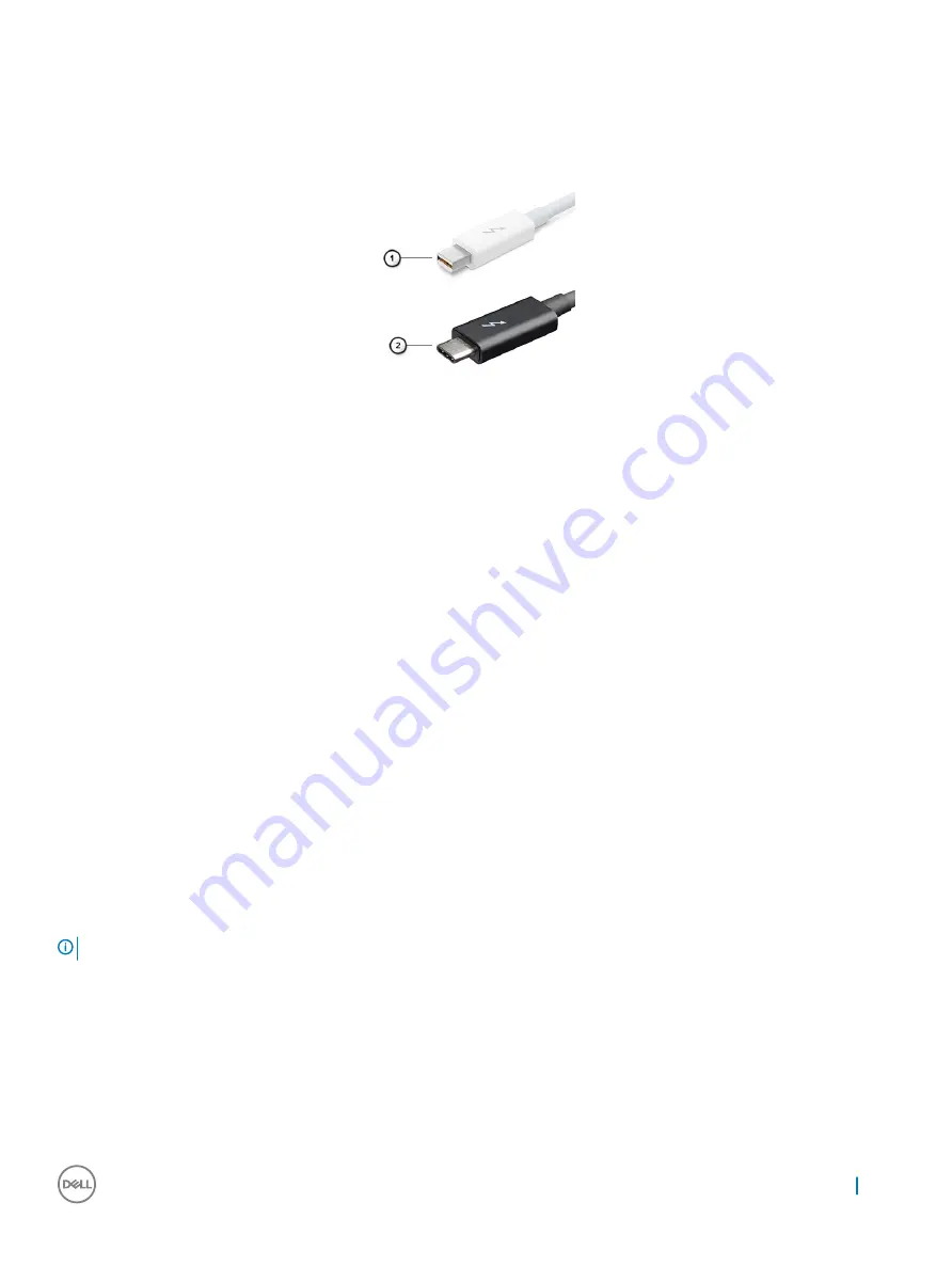
Thunderbolt is a hardware interface that combines data, video, audio, and power in a single connection. Thunderbolt combines PCI Express 
(PCIe) and DisplayPort (DP) into one serial signal, and additionally provides DC power, all in one cable. Thunderbolt 1 and Thunderbolt 2 use 
the same connector as miniDP (DisplayPort) to connect to peripherals, while Thunderbolt 3 uses a USB Type-C connector.

Figure 7. Thunderbolt 1 and Thunderbolt 3

1

Thunderbolt 1 and Thunderbolt 2 (using a miniDP connector) 

2

Thunderbolt 3 (using a USB Type-C connector) 

Thunderbolt 3 over Type-C

Thunderbolt 3 brings Thunderbolt to USB Type-C at speeds up to 40 Gbps, creating one compact port that does it all - delivering the 
fastest, most versatile connection to any dock, display or data device like an external hard drive. Thunderbolt 3 uses a USB Type-C 
connector/port to connect to supported peripherals.

1

Thunderbolt 3 uses USB Type-C connector and cables - It is compact and reversible 

2

Thunderbolt 3 supports speed up to 40 Gbps

3

DisplayPort 1.2 – compatible with existing DisplayPort monitors, devices and cables

4

USB Power Delivery - Up to 130W on supported computers 

Key Features of Thunderbolt 3 over USB Type-C 

1

Thunderbolt, USB, DisplayPort and power on USB Type-C on a single cable (features vary between different products) 

2

USB Type-C connector and cables which are compact and reversible 

3

Supports Thunderbolt Networking (*varies between different products) 

4

Supports up to 4K displays

5

Up to 40 Gbps

NOTE: 

Data transfer speed may vary between different devices.

Technology and components

51

Summary of Contents for Latitude 7285

Page 1: ...Latitude 7285 2 in 1 Owner s Manual Regulatory Model T02J Regulatory Type T02J001 ...

Page 2: ...amage to hardware or loss of data and tells you how to avoid the problem WARNING A WARNING indicates a potential for property damage personal injury or death 2017 Dell Inc or its subsidiaries All rights reserved Dell EMC and other trademarks are trademarks of Dell Inc or its subsidiaries Other trademarks may be trademarks of their respective owners 2017 07 Rev A00 ...

Page 3: ...sing your tablet 12 Turning off Your Tablet 12 Before Working Inside Your Tablet 13 After working inside your tablet 14 3 Removing and Installing components 15 microSIM card 15 microSD card 16 Display Panel 17 Removing the display panel 17 Installing the display panel 23 Battery 23 Removing the battery 23 Installing the battery 24 Power switch board 24 Removing the power button board 24 Installing...

Page 4: ...the thunderbolt over Type C USB bracket 37 System Board 37 Removing the system board 37 Installing the system board 39 Speaker 39 Removing the speaker 39 Installing the speaker 40 Back cover 41 Replacing the back cover 41 4 Technology and components 43 Power adapter 43 Processors 43 Kaby Lake 7th Generation Intel Core processors 43 Chipset 44 Memory features 44 Display options 44 Camera features 4...

Page 5: ...s 61 POST behavior screen options 63 Manageability 64 Virtualization support screen options 64 Wireless screen options 64 Maintenance screen options 65 System logs screen options 65 Updating the BIOS 65 System and setup password 66 Assigning a system password and setup password 66 Deleting or changing an existing system and or setup password 67 6 Troubleshooting 68 Enhanced Pre boot System Assessm...

Page 6: ...ication specifications Camera specifications Display specifications AC adapter specifications Battery specifications Physical specifications Active pen specifications Wireless charging mat specifications Environmental specifications Processor specifications Feature Specification Types 7th Generation Intel Core i5 7Y54 4M Cache up to 3 2 GHz supports Windows 10 only 7th Generation Intel Core i5 7Y5...

Page 7: ...ication Types High definition audio Controller Realtek ALC3253 Stereo conversion 24 bit analog to digital and digital to analog Internal interface High definition audio External interface Microphone in stereo headphones and speakers universal connector Speakers Two Internal speaker amplifier 2 W RMS per channel Volume controls Volume up and Volume down buttons Port and connector specifications Fea...

Page 8: ...eless Qualcomm Snapdragon X7 LTE A DW5816e for Japan WiGig Optional Intel Tri Band Wireless AC 18265 WiGig Wi Fi BT4 2 Wireless Card WiFi Display Miracast Camera specifications Feature Specification Type Front Camera 720P fixed focus Rear Camera 8MP auto focus IR Camera VGA IR camera Sensor type CMOS sensor technology Front and Rear camera Imaging rate Up to 30 frames per second Video Resolution F...

Page 9: ...t voltage 20 VDC Weight 0 64 lbs 0 29 kg Dimensions 1 1 x 1 9 x 4 3 inches 28 x 47 x 108 mm Temperature range Operating 0 C to 40 C 32 F to 104 F Temperature range Non Operating 40 C to 70 C 40 F to 158 F Battery specifications Feature Specification Type 34 Whr Polymer battery with ExpressCharge 34 Whr Long Life Cycle Battery 2 cell 34 Whr Polymer battery with ExpressCharge Length 184 00 mm 7 24 i...

Page 10: ...ard 3 01 lb 1 36 kg Width 10 8 inches 274 8 mm Height 0 3 inch 7 9 mm Depth 8 2 inches 209 2 mm Active pen specifications Feature Specification Model number PN557W Length 6 33 inches 160 6 mm Diameter 0 37 inch 9 5 mm Pressure Resolution 2048 levels Accuracy Resolution Pen contact accuracy is 0 2 mm at 0 tilt 0 4 mm at up to 60 tilt in either stationary or in motion state Pen hover accuracy is les...

Page 11: ...12 28 inch 312 00 mm Width 11 17 inch 283 82 mm Height 0 69 inch 17 73 mm DC Cable length 2 0 m AC Cable length 1 0 m Environmental specifications Temperature Specifications Operating 0 C to 35 C 32 F to 95 F Storage 40 C to 65 C 40 F to 149 F Relative humidity maximum Specifications Operating 10 to 90 non condensing Storage 10 to 95 non condensing Altitude maximum Specifications Operating 0 m to ...

Page 12: ...ff your tablet using power button a Press and hold the Power button until you see Slide to shut down your PC on the screen NOTE After you press and hold the Power button by default the tablet enters sleep mode However if you change the power button setting to shut down the tablet shuts down To change the power button setting go to Control Panel Power Options Change Plan Setting Change Advanced Pow...

Page 13: ...s directed by the online or telephone service and support team Damage due to servicing that is not authorized by Dell is not covered by your warranty Read and follow the safety instructions that came with the product CAUTION To avoid electrostatic discharge ground yourself by using a wrist grounding strap or by periodically touching an unpainted metal surface such as a connector on the back of the...

Page 14: ...f the tablet While you work periodically touch an unpainted metal surface to dissipate static electricity which could harm internal components 6 Remove the storage SD card from the tablet After working inside your tablet NOTE Leaving stray loose screws inside your table may severely damage your tablet 1 Replace all screws and ensure that no stray screws remain inside your tablet 2 Connect any exte...

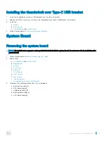
Page 15: ...Audio board Front facing camera Rear facing camera Coin cell battery Docking board Thunderbolt over Type C USB bracket System Board Speaker Back cover microSIM card 1 Insert a paperclip or a microSIM card removal tool into the pinhole on the microSIM card tray 1 2 Insert the microSIM card into the slots indicated on the slot 2 3 Align the cover with the groove on the tablet and slide it inside to ...

Page 16: ... paperclip or a microSD card removal tool into the pinhole on the microSD card tray 1 2 Insert the microSD card into the slots indicated on the slot 2 3 Align the cover with the groove on the tablet and slide it inside to secure the microSD 3 16 Removing and Installing components ...

Page 17: ...ocedure in Before working inside your tablet 2 Remove the microSIM card and microSD card 3 To release the display panel with plastic scribe a Remove the M2x4 4 screws that secure the display panel to the tablet 1 b Use a plastic scribe to remove the microSIM microSD cover 2 Removing and Installing components 17 ...

Page 18: ...4 Insert a plastic scribe into the microSIM microSD slot 5 Pry the edges starting from microSIM microSD slot 1 2 18 Removing and Installing components ...

Page 19: ...he tablet 1 b Attach a suction cup to the display panel above the left docking slot located at the bottom of the system while inserting a plastic scribe into the left docking slot to stabilize the system and then carefully pull open the display panel using the suction cup Removing and Installing components 19 ...

Page 20: ...7 Lift the display panel from the tablet 8 Slide the display panel 1 and flip the display panel 2 20 Removing and Installing components ...

Page 21: ...p open the display panel to a 180 degree angle and lay it flat on the surface 10 To disconnect the display cable a Remove the M1 6x2 5 1 screw that secures the metal bracket on the system board 1 b Lift the metal tab and disconnect the battery cable 2 c Remove the adhesive tape that secure the display cable on the system board 3 d Remove the M1 6x2 5 2 screws that secures display cable 4 Removing ...

Page 22: ...Lift the tab and disconnect the display cable 6 NOTE Only disconnect the display cable from the system board DO NOT disconnect the display cable from the display panel 11 Remove the display panel from the tablet 22 Removing and Installing components ...

Page 23: ...ce the M1 6x2 5 1 screw that secures the connector on the system board 6 Install the display panel on the tablet and press the edges until they snap in 7 Replace the M2x4 4 screws to secure the tablet to the display panel 8 Install microSIM card and microSD card 9 Follow the procedure in After working inside your tablet Battery Removing the battery 1 Follow the procedure in Before working inside y...

Page 24: ...ry 1 Insert the battery into the slot on the tablet 2 Replace the M2x3 4 screws to secure the battery to the tablet 3 Install the a display panel b microSIM card and microSD card 4 Follow the procedure in After working inside your tablet Power switch board Removing the power button board 1 Follow the procedure in Before working inside your tablet 2 Remove the a microSIM card and microSD card b dis...

Page 25: ...re the power button board to the tablet 3 Connect the power button board cable and close the latch on the tablet 4 Install the a battery b display panel c microSIM card and microSD card 5 Follow the procedure in After working inside your tablet WLAN card Removing the WLAN card 1 Follow the procedure in Before working inside your tablet 2 Remove the a microSIM card and microSD card b display panel ...

Page 26: ...ector on the system board 2 Connect the antenna cables to the WLAN card 3 Insert the WLAN bracket to the WLAN card 4 Replace the M2x2 0 1 screw to secure the WLAN bracket 5 Install the a battery b display panel c microSIM card and microSD card 6 Follow the procedure in After working inside your tablet PCIe Solid State Drive SSD Removing the SSD module 1 Follow the procedure in Before working insid...

Page 27: ...let 3 Installing the SSD module 1 Insert the SSD module into the connector on the system board 2 Install the SSD shield on the SSD module 3 Replace the M2x2 0 1 screw to secure SSD shield NOTE Align the shield carefully or else it may break 4 Install the a battery b display panel c microSIM card and microSD card 5 Follow the procedure in After working inside your tablet Removing and Installing com...

Page 28: ...screw securing the WWAN bracket 1 b Lift the WWAN bracket from the tablet 2 c Disconnect the antenna cables from the WWAN card 3 d Slide and lift the WWAN card from the connector on the system board 4 Installing the WWAN card 1 Insert the WWAN card into the connector on the system board 2 Connect the antenna cables to the WWAN card 3 Insert the WLAN bracket to the WWAN card 28 Removing and Install...

Page 29: ... Follow the procedure in Before working inside your tablet 2 Remove the a microSIM card and microSD card b display panel c battery 3 To remove the audio port a Lift the latch and disconnect the audio port connector 1 b Peel the audio port cable from the tablet 2 c Remove the M2X3 2 screw that secures the audio port on the system board 3 d Lift the audio port from the system board 4 Removing and In...

Page 30: ...IM card and microSD card 6 Follow the procedure in After working inside your tablet Front facing camera Removing the front camera 1 Follow the procedure in Before working inside your tablet 2 Remove the a microSIM card and microSD card b display panel c battery 3 To remove the front facing camera a Lift the latch and disconnect the camera connector 1 b Remove the M1 6x2 5 2 screws that secure the ...

Page 31: ...odule 3 Connect the front camera cable to the system board 4 Install the a battery b display panel c microSIM card and microSD card 5 Follow the procedure in After working inside your tablet Rear facing camera Removing the rear camera 1 Follow the procedure in Before working inside your tablet 2 Remove the Removing and Installing components 31 ...

Page 32: ...connect the front camera cable 1 b Remove the front camera cable from the system board 2 4 To remove the rear camera a Disconnect the rear camera cable from the system board 1 b Remove the M1 6x2 5 1 screw securing the rear camera module 2 c Lift the camera module from the tablet 3 32 Removing and Installing components ...

Page 33: ...board 4 Connect the front camera cable to the system board 5 Install the a battery b display panel c microSIM card and microSD card 6 Follow the procedure in After working inside your tablet Coin cell battery Removing the coin cell battery 1 Follow the procedure in Before working inside your tablet 2 Remove the a microSIM card and microSD card b display panel Removing and Installing components 33 ...

Page 34: ... and lift it away from the system board 2 Installing the coin cell battery 1 Place the coin cell battery into the slot on the system board 2 Connect the coin cell battery cable to the connector on the system board 3 Install the a front facing camera b battery c display panel d microSIM card and microSD card 4 Follow the procedure in After working inside your tablet 34 Removing and Installing compo...

Page 35: ...d a Disconnect the docking board cable from the system board 1 b Remove the M1 6x4 2 screws securing the docking board bracket to the docking board 2 c Remove the docking board bracket 3 d Lift the docking board from the tablet 4 Installing the docking board 1 Insert the docking board into the slot on the tablet 2 Place the docking board metal on the docking board Removing and Installing component...

Page 36: ... tablet Thunderbolt over Type C USB bracket Removing the thunderbolt over Type C bracket 1 Follow the procedure in Before working inside your tablet 2 Remove the a microSIM card and microSD card b display panel c battery 3 To release the thunderbolt over Type C bracket a Remove the M2x2 0 3 screws securing the thunderbolt over Type C bracket to the tablet 1 b Slide and lift the thunderbolt over Ty...

Page 37: ...d NOTE Heat sink is not a separate service part but is included with the system board Do not remove the heat sink from the system board 1 Follow the procedure in Before working inside your tablet 2 Remove the a microSIM card and microSD card b display panel c battery d WLAN card e SSD card f WWAN card g front camera h rear camera i coin cell battery j thunderbolt over Type C USB bracket 3 Disconne...

Page 38: ...4 To remove system board a Remove the M1 6x1 5 4 screw that secures the system board to the tablet 1 b Lift the system board from the tablet 2 38 Removing and Installing components ...

Page 39: ...mera d front camera e WWAN card f SSD card g WLAN card h battery i display panel j microSIM card and microSD card 5 Follow the procedure in After working inside your tablet Speaker Removing the speaker 1 Follow the procedure in Before working inside your tablet 2 Remove the a microSIM card and microSD card b display panel c battery d WLAN card e SSD card f WWAN card g front camera h rear camera i ...

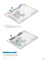
Page 40: ...speaker adhesive cable from the tablet 1 b Lift the speaker from the tablet 2 Installing the speaker 1 Align the speaker with the holders on the tablet 2 Affix the speaker adhesive tape on the tablet 40 Removing and Installing components ...

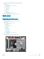
Page 41: ...procedure in After working inside your tablet Back cover Replacing the back cover 1 Follow the procedure in Before working inside your tablet 2 Remove the a microSIM card and microSD card b display panel c battery d power button board e WLAN card f SSD card g WWAN card h audio port i front camera j rear camera k coin cell battery l Docking board m thunderbolt over Type C USB bracket n system board...

Page 42: ...c docking board d coin cell battery e rear camera f front camera g audio port h WWAN card i SSD card j WLAN card k power button board l battery m display panel n microSIM card and microSD card 5 Follow the procedure in After working inside your tablet 42 Removing and Installing components ...

Page 43: ...ong countries Using an incompatible cable or improperly connecting the cable to the power strip or electrical outlet may cause fire or equipment damage Processors Kaby Lake 7th Generation Intel Core processors The 7th Gen Intel Core processor Kaby Lake family is the successor of 6th generation processors Skylake It s main features include Intel 14nm Manufacturing Process Technology Intel Turbo Boo...

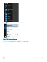
Page 44: ...ning Gorilla Glass Antireflective and Antismudge display Camera features This system is shipped with front facing camera with 5 MP and rear facing camera with 8 MP Starting the camera To start the camera open an application that uses the camera For instance if you tap the Dell webcam central software or the Skype software that is shipped with the 2 in 1 the camera turns on Similarly if you are cha...

Page 45: ...3 If the Camera App is not available in the apps list search for it Hard drive options This system supports M 2 SATA SSD M 2 PCIe NVMe SSD and M 2 PCIe NVMe SED Technology and components 45 ...

Page 46: ...Drivers This section lists the drivers associated with the components shipped with your tablet System drivers Figure 1 System drivers 46 Technology and components ...

Page 47: ...Disk driver Figure 2 Disk driver Technology and components 47 ...

Page 48: ...Sound video and game controller drivers Figure 3 Sound video and game controllers 48 Technology and components ...

Page 49: ...Storage controller drivers Figure 4 Storage controllers Technology and components 49 ...

Page 50: ...Network drivers Figure 5 Network drivers Graphics driver Figure 6 Graphics driver 50 Technology and components ...

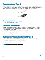
Page 51: ...ll delivering the fastest most versatile connection to any dock display or data device like an external hard drive Thunderbolt 3 uses a USB Type C connector port to connect to supported peripherals 1 Thunderbolt 3 uses USB Type C connector and cables It is compact and reversible 2 Thunderbolt 3 supports speed up to 40 Gbps 3 DisplayPort 1 2 compatible with existing DisplayPort monitors devices and...

Page 52: ...Thunderbolt Icons 52 Technology and components ...

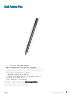
Page 53: ...ilt in magnet for increased fastening strength Removed Pen clip and added Tethering functionality Customizable 2 barrel buttons and Top button Quick launch and note taking over lock screen requires Bluetooth pairing LED light to show Bluetooth pairing status 12 months battery life with AAAA battery Need to install Active Control Panel from dell com support drivers Based on 3 hours daily usage for ...

Page 54: ... with selected Dell notebooks Suitable for Category 5 AirFuel certified PRUs Dell branded products carry a 1 year limited hardware warranty CAUTION Do not insert any objects between the keyboard and the wireless charging mat or between the wireless charging mat and the table Specifically avoid CD DVDs RFID cards devices credit cards and other thin metal objects These devices may be damaged if they...

Page 55: ... Up button 4 Press the Volume Down button to enter BIOS setup program System setup options NOTE Depending on the tabletnotebook and its installed devices the items listed in this section may or may not appear General screen options This section lists the primary hardware features of your computer Option Description System Information Lists the primary hardware features of your computer System Info...

Page 56: ...he date and time System Configuration screen options Option Description SATA Operation Allows you to configure the internal SATA hard drive controller The options are Disabled AHCI RAID On selected by default Drives Allows you to configure the SATA drives on board All drives are enabled by default The options are M 2 PCI e SSD 0 selected by default M 2 PCI e SSD 1 selected by default SMART Reporti...

Page 57: ...bles or disables the integrated audio controller By default the Enable Audio option is selected The options are Enable Microphone selected by default Enable Internal Speaker selected by default Keyboard Illumination This field lets you choose the operating mode of the keyboard illumination feature The keyboard brightness level can be set from 0 to 100 The options are Disabled selected by default D...

Page 58: ...al SD Card Read Only Mode Video screen options Option Description LCD Brightness Allows you to set the display brightness depending upon the power source On Battery and On AC The LCD brightness is independent for battery and AC adapter It can be set using the slider NOTE The video setting is visible only when a video card is installed into the system Security screen options Option Description Admi...

Page 59: ...lowed when an Administrator Password is set If disabled the setup options are locked by the admin password Option allow wireless switch changes is not selected by default UEFI capsule firmware updates This option controls whether the system allows BIOS updates using UEFI capsule update packages This option is enabled by default TPM 2 0 Security Allows you to enable the Trusted Platform Module TPM ...

Page 60: ...ar The options are Save to File Saves the key to a user selected file Replace from File Replaces the current key with a key from a user selected file Append from File Adds a key to the current database from a user selected file Delete Deletes the selected key Reset All Keys Resets to default setting Delete All Keys Deletes all the keys NOTE If you disable the Custom Mode all the changes made are e...

Page 61: ... SpeedStep Default setting The option is enabled C States Control Allows you to enable or disable the additional processor sleep states C states Default setting The option is enabled Intel TurboBoost Allows you to enable or disable the Intel TurboBoost mode of the processor Enable Intel TurboBoost Default setting The option is enabled HyperThread Control Allows you to enable or disable the Hyper T...

Page 62: ...he AC is attached Enable peak shift Set battery threshold 15 to 100 15 Advanced Battery Charge Configuration This option enables you to maximize the battery health By enabling this option your system uses the standard charging algorithm and other techniques during the non work hours to improve the battery health Enable Advanced Battery Charge Mode Primary Battery Charge Configuration Allows you to...

Page 63: ...tions Allows you to let hot key combinations Fn Esc toggle the primary behavior of F1 F12 between their standard and secondary functions If you disable this option you cannot toggle dynamically the primary behavior of these keys The available options are Lock Mode Disable Standard selected by default Lock Mode Enable Secondary Fastboot Allows you to speed up the boot process by bypassing some of t...

Page 64: ...om utilizing the additional hardware capabilities provided by Intel Virtualization technology for direct I O Enable VT for Direct I O selected by default Trusted Execution This option specifies whether a Measured Virtual Machine Monitor MVMM can utilize the additional hardware capabilities provided by Intel Trusted Execution Technology The TPM Virtualization Technology and the Virtualization techn...

Page 65: ...ystem logs screen options Option Description BIOS Events Allows you to view and clear the System Setup BIOS POST events Thermal Events Allows you to view and clear the System Setup Thermal events Power Events Allows you to view and clear the System Setup Power events Updating the BIOS It is recommended to update your BIOS System setup on replacing the system board or if an update is available Ensu...

Page 66: ...etup password Password that you must enter to access and make changes to the BIOS settings of your computer CAUTION The password features provide a basic level of security for the data on your computer CAUTION Anyone can access the data stored on your computer if it is not locked and left unattended NOTE Your computer is shipped with the system and setup password feature is disabled Assigning a sy...

Page 67: ...rity and press Enter The System Security screen is displayed 2 In the System Security screen verify that Password Status is Unlocked 3 Select System Password alter or delete the existing system password and press Enter or Tab 4 Select Setup Password alter or delete the existing setup password and press Enter or Tab NOTE If you change the System and or Setup password re enter the new password when ...

Page 68: ... 2 Before the Dell Logo is displayed immediately press the Volume Up button to get the Boot Menu 3 Scroll down the Diagnostics and then press the Volume Down button to select 4 The tablet will begin running the ePSA utility Dell wireless charging mat Ensure that the correct AC adapter is plugged into the charging mat and AC input is connected and supplied to the adapter Ensure that the charging ma...

Page 69: ...2 1 processor processor failure 2 2 system board BIOS ROM system board covers BIOS corruption or ROM error 2 3 memory no memory no RAM detected 2 4 memory memory failure RAM failure 2 5 memory invalid memory installed 2 6 system board chipset system board chipset error 2 7 display display failure 3 1 RTC power failure coin cell battery failure 3 2 PCI Video PCI Video card chip failure 3 3 BIOS rec...

Page 70: ...ying the AC adapter shipped with your notebooktablet AC adapters are shipped based on customer requirements or based on regions To identify the AC adapter shipped with your tabletnotebook you can verify it from the service tag 1 Go to Dell com support 2 Type the service tag of your tabletnotebook 3 Click System configuration System configuration details are displayed 4 Click Original configuration...

Page 71: ... service options Availability varies by country and product and some services may not be available in your area To contact Dell for sales technical support or customer service issues 1 Go to Dell com support 2 Select your support category 3 Verify your country or region in the Choose a Country Region drop down list at the bottom of the page 4 Select the appropriate service or support link based on...

Reviews: