background image

Back to Contents Page


 Coin-Cell Battery  

Dell™ Inspiron™ N5110 Service Manual 


Removing the Coin-Cell Battery 


Replacing the Coin-Cell Battery 


Removing the Coin-Cell Battery  


1.

Follow the instructions in 

Before You Begin

.  


2.

Remove the battery (see 

Removing the Battery

).  


3.

Follow the instructions from 

step 3

 to 

step 9

 in 

Removing the Palm-Rest Assembly


4.

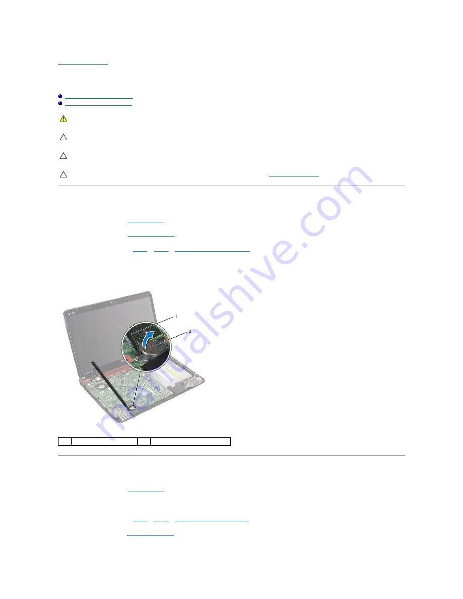
Use a plastic scribe and gently pry the coin-cell out of the battery socket on the system board.  


5.

Lift the coin-cell battery out of the battery socket.  


Replacing the Coin-Cell Battery  


1.

Follow the instructions in 

Before You Begin

.  


2.

With the positive side up, snap the coin-cell battery into the battery socket on the system board.  


3.

Follow the instructions from 

step 2

 to 

step 7

 in 

Replacing the Palm-Rest Assembly


4.

Replace the battery (see 

Replacing the Battery

).  


WARNING: 

Before working inside your computer, read the safety information that shipped with your computer. For additional safety best 

practices information, see the Regulatory Compliance Homepage at www.dell.com/regulatory_compliance. 


CAUTION: 

Only a certified service technician should perform repairs on your computer. Damage due to servicing that is not authorized by Dell is 

not covered by your warranty.


CAUTION: 

To avoid electrostatic discharge, ground yourself by using a wrist grounding strap or by periodically touching an unpainted metal 

surface (such as a connector on your computer).


CAUTION: 

To help prevent damage to the system board, remove the main battery (see 

Removing the Battery

) before working inside the 

computer.

plastic scribe 

coin-cell battery 

Summary of Contents for Inspiron N5110

Page 1: ...ritten permission of Dell Inc is strictly forbidden 2011 02 Rev A00 Regulatory model P17F Regulatory type P17F001 Before You Begin Top Cover Battery Module Cover Memory Module s Optical Drive Keyboard Palm Rest Assembly Wireless Mini Card s Display Hinge Cover Camera Module Coin Cell Battery System Board Speakers Hard Drive Thermal Cooling Assembly Processor Module I O Board VGA Power Board Flashi...

Page 2: ...e working inside your computer read the safety information that shipped with your computer For additional safety best practices information see the Regulatory Compliance Homepage at dell com regulatory_compliance CAUTION Only a certified service technician should perform repairs on your computer Damage due to servicing that is not authorized by Dell is not covered by your warranty CAUTION To avoid...

Page 3: ...your own personal safety Before working inside your computer read the safety information that shipped with your computer For additional safety best practices information see the Regulatory Compliance Homepage at dell com regulatory_compliance 1 Ensure that the work surface is flat and clean to prevent the computer cover from being scratched CAUTION To avoid losing data save and close all open file...

Page 4: ...lets 6 Disconnect all attached devices from your computer 7 Remove the battery see Removing the Battery 8 Turn the computer top side up open the display and press the power button to ground the system board Back to Contents Page CAUTION To disconnect a network cable first unplug the cable from your computer and then unplug the cable from the network device CAUTION To help prevent damage to the sys...

Page 5: ...brand in the Select Your Product Line list d Select the product model number in the Select Your Product Model list e Click Confirm 4 A list of results appear on the screen Click BIOS 5 Click Download Now to download the latest BIOS file The File Download window appears 6 Click Save to save the file on your desktop The file downloads to your desktop 7 Click Close if the Download Complete window app...

Page 6: ...d adhere it in place 3 Replace the display panel see Replacing the Display Panel 4 Replace the display bezel see Replacing the Display Bezel 5 Replace the display assembly see Replacing the Display Assembly WARNING Before working inside your computer read the safety information that shipped with your computer For additional safety best practices information see the Regulatory Compliance Homepage a...

Page 7: ...the Palm Rest Assembly 7 Replace the battery see Replacing the Battery Back to Contents Page CAUTION Before turning on the computer replace all screws and ensure that no stray screws remain inside the computer Failure to do so may result in damage to the computer ...

Page 8: ...low the instructions from step 2 to step 7 in Replacing the Palm Rest Assembly 4 Replace the battery see Replacing the Battery WARNING Before working inside your computer read the safety information that shipped with your computer For additional safety best practices information see the Regulatory Compliance Homepage at www dell com regulatory_compliance CAUTION Only a certified service technician...

Page 9: ...Back to Contents Page CAUTION Before turning on the computer replace all screws and ensure that no stray screws remain inside the computer Failure to do so may result in damage to the computer ...

Page 10: ... Replace the two screws that secure the I O board to the computer base 3 Replace the Mini Card s see Replacing the Mini Card s 4 Replace the hinge cover see Replacing the Hinge Cover 5 Follow the instructions from step 6 to step 15 in Replacing the System Board WARNING Before working inside your computer read the safety information that shipped with your computer For additional safety best practic...

Page 11: ...ly see Replacing the Display Assembly Back to Contents Page CAUTION Before turning on the computer replace all screws and ensure that no stray screws remain inside the computer Failure to do so may result in damage to the computer ...

Page 12: ...p 16 in Replacing the System Board 5 Replace the display assembly see Replacing the Display Assembly Back to Contents Page WARNING Before working inside your computer read the safety information that shipped with your computer For additional safety best practices information see the Regulatory Compliance Homepage at www dell com regulatory_compliance CAUTION Only a certified service technician sho...

Page 13: ......

Page 14: ...ng guides 8 Remove the four screws that secure the display assembly to the computer base 9 Lift the display assembly off the computer base WARNING Before working inside your computer read the safety information that shipped with your computer For additional safety best practices information see the Regulatory Compliance Homepage at dell com regulatory_compliance CAUTION Only a certified service te...

Page 15: ...the display assembly to the computer base 8 Replace the battery see Replacing the Battery Display Bezel Removing the Display Bezel 1 Follow the instructions in Before You Begin 2 Remove the top cover see Removing the Top Cover 3 Remove the display assembly see Removing the Display Assembly 4 Using your fingertips carefully pry up the inside edge of the display bezel 5 Remove the display bezel 1 di...

Page 16: ...Before You Begin 2 Remove the display assembly see Removing the Display Assembly 3 Remove the display bezel see Removing the Display Bezel 4 Disconnect the camera cable from the connector on the camera module 5 Remove the eight screws that secure the display panel to the display back cover 6 Lift the display panel off the display back cover 1 display bezel CAUTION Before turning on the computer re...

Page 17: ...uting guides on the display back cover 6 Align the screw holes on the display panel with the screw holes on the display back cover and replace the eight screws 7 Replace the display bezel see Replacing the Display Bezel 8 Replace the display assembly see Replacing the Display Assembly Display Cable Removing the Display Cable 1 Follow the instructions in Before You Begin 2 Remove the display assemb...

Page 18: ...ackets Removing the Display Panel Brackets 1 Follow the instructions in Before You Begin 2 Remove the display assembly see Removing the Display Assembly 3 Remove the display bezel see Removing the Display Bezel 4 Remove the display panel see Removing the Display Panel 5 Remove the four screws two on each side that secure the display panel brackets to the display panel 1 display cable 2 tape CAUTIO...

Page 19: ...h side 3 Replace the display panel see Replacing the Display Panel 4 Replace the display bezel see Replacing the Display Bezel 5 Replace the display assembly see Replacing the Display Assembly Back to Contents Page 1 display brackets 2 2 screws 4 CAUTION Before turning on the computer replace all screws and ensure that no stray screws remain inside the computer Failure to do so may result in damag...

Page 20: ... hot do not touch the metal housing of the hard drive CAUTION Only a certified service technician should perform repairs on your computer Damage due to servicing that is not authorized by Dell is not covered by your warranty CAUTION To avoid electrostatic discharge ground yourself by using a wrist grounding strap or by periodically touching an unpainted metal surface such as a connector on your co...

Page 21: ... 5 Place the hard drive assembly on the system board 6 Slide the hard drive assembly to connect it to the system board connector 7 Replace the two screws that secure the hard drive assembly to the system board 8 Follow the instructions from step 6 to step 15 in Replacing the System Board Back to Contents Page 1 screws 4 2 hard drive bracket CAUTION Before turning on the computer replace all screws...

Page 22: ...ore You Begin 2 Align the screw holes on the thermal cooling assembly with the screw holes on the system board 3 Tighten the five screws that secure the thermal cooling assembly to the system board WARNING Before working inside your computer read the safety information that shipped with your computer For additional safety best practices information see the Regulatory Compliance Homepage at www del...

Page 23: ...ard 6 Follow the instructions from step 4 to step 12 in Replacing the System Board 7 Replace the battery see Replacing the Battery Back to Contents Page CAUTION Before turning on the computer replace all screws and ensure that no stray screws remain inside the computer Failure to do so may result in damage to the computer ...

Page 24: ...de your computer read the safety information that shipped with your computer For additional safety best practices information see the Regulatory Compliance Homepage at dell com regulatory_compliance CAUTION Only a certified service technician should perform repairs on your computer Damage due to servicing that is not authorized by Dell is not covered by your warranty CAUTION To avoid electrostatic...

Page 25: ...ce 3 Replace the four screws that secure the hinge cover to the computer base 4 Replace the display assembly see Replacing the Display Assembly 5 Replace the battery see Replacing the Battery Back to Contents Page CAUTION Before turning on the computer replace all screws and ensure that no stray screws remain inside the computer Failure to do so may result in damage to the computer ...

Page 26: ...s information see the Regulatory Compliance Homepage at dell com regulatory_compliance CAUTION Only a certified service technician should perform repairs on your computer Damage due to servicing that is not authorized by Dell is not covered by your warranty CAUTION To avoid electrostatic discharge ground yourself by using a wrist grounding strap or by periodically touching an unpainted metal surfa...

Page 27: ...to secure the cable 3 Slide the tabs on the keyboard into the slots on the palm rest assembly and lower the keyboard into place 4 Gently press around the edges of the keyboard and slide it upwards to secure the keyboard under the tabs on the palm rest 5 Close the display and turn the computer over 6 Replace the battery see Replacing the Battery Back to Contents Page 1 keyboard cable 2 keyboard cab...

Page 28: ...nside your computer read the safety information that shipped with your computer For additional safety best practices information see the Regulatory Compliance Homepage at dell com regulatory_compliance CAUTION Only a certified service technician should perform repairs on your computer Damage due to servicing that is not authorized by Dell is not covered by your warranty CAUTION To avoid electrosta...

Page 29: ...nect the AC adapter to your computer and an electrical outlet 6 Turn on the computer As the computer boots it detects the memory module s and automatically updates the system configuration information To confirm the amount of memory installed in the computer Click Start Control Panel System and Security System Back to Contents Page NOTE If the memory module is not installed properly the computer m...

Page 30: ...i Card c Remove the screw that secures the Mini Card to the system board d Lift the Mini Card out of the system board connector WARNING Before working inside your computer read the safety information that shipped with your computer For additional safety best practices information see the Regulatory Compliance Homepage at www dell com regulatory_compliance CAUTION Only a certified service technicia...

Page 31: ...is not in the computer store it in protective antistatic packaging For more information see Protecting Against Electrostatic Discharge in the safety information that shipped with your computer CAUTION Use firm and even pressure to slide the card into place If you use excessive force you may damage the connector CAUTION The connectors are keyed to ensure correct insertion If you feel resistance che...

Page 32: ... Replace the battery see Replacing the Battery Back to Contents Page WARNING Before working inside your computer read the safety information that shipped with your computer For additional safety best practices information see the Regulatory Compliance Homepage at dell com regulatory_compliance CAUTION Only a certified service technician should perform repairs on your computer Damage due to servici...

Page 33: ......

Page 34: ...ontents Page WARNING Before working inside your computer read the safety information that shipped with your computer For additional safety best practices information see the Regulatory Compliance Homepage at dell com regulatory_compliance CAUTION Only a certified service technician should perform repairs on your computer Damage due to servicing that is not authorized by Dell is not covered by your...

Page 35: ......

Page 36: ...e system board WARNING Before working inside your computer read the safety information that shipped with your computer For additional safety best practices information see the Regulatory Compliance Homepage at dell com regulatory_compliance CAUTION Only a certified service technician should perform repairs on your computer Damage due to servicing that is not authorized by Dell is not covered by yo...

Page 37: ... on the palm rest assembly with the slots on the computer base and gently snap the palm rest assembly in place 3 Slide the touch pad cable power button board cable and hot key board cable into the connectors on the system board and press down on the connector latches to secure them 1 power button board cable 2 touch pad cable 3 screws 4 4 hot key board cable CAUTION Carefully separate the palm res...

Page 38: ... computer over 7 Replace the six screws that secure the palm rest assembly to the computer base 8 Replace the battery see Replacing the Battery Back to Contents Page CAUTION Before turning on the computer replace all screws and ensure that no stray screws remain inside the computer Failure to do so may result in damage to the computer ...

Page 39: ... CAUTION Only a certified service technician should perform repairs on your computer Damage due to servicing that is not authorized by Dell is not covered by your warranty CAUTION To avoid electrostatic discharge ground yourself by using a wrist grounding strap or by periodically touching an unpainted metal surface such as a connector on your computer CAUTION To help prevent damage to the system b...

Page 40: ...ng the System Board Back to Contents Page NOTE If a new processor is installed you will receive a new thermal cooling assembly which will include an affixed thermal pad or you will receive a new thermal pad along with documentation to illustrate proper installation NOTE The pin 1 corner of the processor module has a triangle that aligns with the triangle on the pin 1 corner of the ZIF socket CAUTI...

Page 41: ...er read the safety information that shipped with your computer For additional safety best practices information see the Regulatory Compliance Homepage at www dell com regulatory_compliance CAUTION To avoid electrostatic discharge ground yourself by using a wrist grounding strap or by periodically touching an unpainted metal surface such as a connector on your computer CAUTION Only a certified serv...

Page 42: ...five screws that secure the system board to the computer base 12 Lift the system board assembly to disconnect the connector on the system board from the connector on the I O board WARNING Before working inside your computer read the safety information that shipped with your computer For additional safety best practices information see the Regulatory Compliance Homepage at dell com regulatory_compl...

Page 43: ...10 Replace the hinge cover see Replacing the Hinge Cover 11 Replace the display assembly see Replacing the Display Assembly 12 Follow the instructions from step 2 to step 7 in Replacing the Palm Rest Assembly 13 Replace the memory module see Replacing the Memory Module s 14 Replace the module cover see Replacing the Module Cover 15 Replace the battery see Replacing the Battery 16 Replace any cards...

Page 44: ...Back to Contents Page ...

Page 45: ...y best practices information see the Regulatory Compliance Homepage at dell com regulatory_compliance CAUTION Only a certified service technician should perform repairs on your computer Damage due to servicing that is not authorized by Dell is not covered by your warranty CAUTION To avoid electrostatic discharge ground yourself by using a wrist grounding strap or by periodically touching an unpain...

Page 46: ...www s manuals com ...

Reviews: