background image

7. Remove the 

wireless card

.

8. Remove the 

solid-state drive

.

9. Remove the 

heat sink

.

About this task

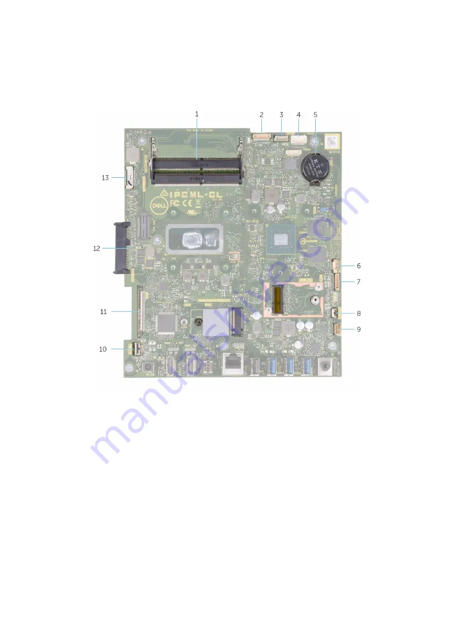
The following image indicates the connectors on your system board.

Figure 1. System-board connectors

1. Memory module
2. Camera cable
3. Touchscreen cable
4. Debug port
5. Coin-cell battery
6. Fan cable
7. Microphone-module cable
8. Media-card reader cable
9. Speaker cable
10. Power-button board cable
11. Display cable
12. Hard-drive connector
13. Backlit cable

The following image indicates the location of system board and provides a visual representation of the removal procedure.

46

Removing and installing components

Summary of Contents for Inspiron 24-5491

Page 1: ...Inspiron 24 5491 Service Manual Regulatory Model W24C Regulatory Type W24C001 ...

Page 2: ...amage to hardware or loss of data and tells you how to avoid the problem WARNING A WARNING indicates a potential for property damage personal injury or death 2019 Dell Inc or its subsidiaries All rights reserved Dell EMC and other trademarks are trademarks of Dell Inc or its subsidiaries Other trademarks may be trademarks of their respective owners 2019 07 Rev A00 ...

Page 3: ...the stand 14 Installing the stand 15 Hard drive 16 Removing the hard drive 16 Installing the hard drive 17 System board shield 18 Removing the system board shield 18 Installing the system board shield 19 Memory modules 20 Removing the memory modules 20 Installing the memory modules 21 Coin cell battery 22 Removing the coin cell battery 22 Installing the coin cell battery 23 Heat sink 24 Removing t...

Page 4: ...ng the system board 47 Base panel 50 Removing the base panel 50 Installing the base panel 52 Display panel 54 Removing the display panel 54 Installing the display panel 55 3 Device drivers 59 Intel Chipset Software Installation Utility 59 Video drivers 59 Intel Serial IO driver 59 Intel Trusted Execution Engine Interface 59 Intel Virtual Button driver 59 Wireless and Bluetooth drivers 59 4 System ...

Page 5: ... built in self test 68 Diagnostics 69 Recovering the operating system 69 Flashing BIOS USB key 70 Flashing the BIOS 70 WiFi power cycle 70 Flea power release 71 6 Getting help and contacting Dell 72 Contents 5 ...

Page 6: ...computer While you work periodically touch an unpainted metal surface to dissipate static electricity which could harm internal components CAUTION When you disconnect a cable pull on its connector or on its pull tab not on the cable itself Some cables have connectors with locking tabs or thumb screws that you must disengage before disconnecting the cable When disconnecting cables keep them evenly ...

Page 7: ...nts in a static safe area If possible use anti static floor pads and workbench pads When unpacking a static sensitive component from its shipping carton do not remove the component from the anti static packing material until you are ready to install the component Before unwrapping the anti static packaging ensure that you discharge static electricity from your body Before transporting a static sen...

Page 8: ...e returned to Dell it is critical to place these parts in anti static bags for safe transport ESD protection summary It is recommended that all field service technicians use the traditional wired ESD grounding wrist strap and protective anti static mat at all times when servicing Dell products In addition it is critical that technicians keep sensitive parts separate from all insulator parts while ...

Page 9: ...y modules 4 base panel 5 display assembly base 6 hard drive 7 system board 8 solid state drive 9 microphones 2 10 wireless card shield 11 media card reader 12 speakers 2 13 password clear jumper 14 CMOS clear jumper 15 fan 16 heat sink Recommended tools The procedures in this document may require the following tools Phillips screwdriver 1 Flat head screwdriver Plastic scribe 2 Removing and install...

Page 10: ...tity Screw image Stand Display assembly base M3x4 8 Bottom cover Display assembly base M3 0 5x5 5 Hard drive assembly Display assembly base M3 0 5x5 2 Hard drive bracket Hard drive M3x3 5 4 System board shield Display assembly base M3 0 5x5 4 Retractable camera assembly door Base panel M3 0 5x5 2 Retractable camera bezel Retractable camera bracket M3 0 5x5 3 Speakers Display assembly base M3 4 7 1...

Page 11: ...nd flat surface Place the display flat on the surface with the stand hanging over the edge It is recommended to remove the stand to avoid accidental damage to the computer display during servicing About this task The following image indicates the location of the back cover and provides a visual representation of the removal procedure Steps 1 Place your palm in the middle of the back cover then pry...

Page 12: ...he slots on the back cover with the slots on the computer and press along the side to snap the back cover into place Next steps 1 Follow the procedure in After working inside your computer Bottom cover Removing the bottom cover Prerequisites 1 Follow the procedure in Before working inside your computer 2 Remove the back cover About this task The following image indicates the location of the bottom...

Page 13: ...ly base Installing the bottom cover Prerequisites If you are replacing a component remove the existing component before performing the installation procedure About this task The following image indicates the location of the bottom cover and provides a visual representation of the installation procedure Removing and installing components 13 ...

Page 14: ...requisites 1 Follow the procedure in Before working inside your computer CAUTION When servicing the computer place it on an elevated clean and flat surface Place the display flat on the surface with the stand hanging over the edge It is recommended to remove the stand to avoid accidental damage to the computer display during servicing 2 Remove the back cover 3 Remove the bottom cover About this ta...

Page 15: ...splay assembly base and lift the stand off the display assembly base Installing the stand Prerequisites If you are replacing a component remove the existing component before performing the installation procedure About this task The following image indicates the location of the stand and provides a visual representation of the installation procedure Removing and installing components 15 ...

Page 16: ...t steps 1 Install the bottom cover 2 Install the back cover 3 Follow the procedure in After working inside your computer Hard drive Removing the hard drive Prerequisites 1 Follow the procedure in Before working inside your computer 2 Remove the back cover 3 Remove the bottom cover 4 Remove the stand About this task The following image indicates the location of the hard drive and provides a visual ...

Page 17: ... secure the hard drive bracket to the hard drive 4 Remove the hard drive bracket off the hard drive Installing the hard drive Prerequisites If you are replacing a component remove the existing component before performing the installation procedure About this task The following image indicates the location of the hard drive and provides a visual representation of the installation procedure Removing...

Page 18: ...ssembly base Next steps 1 Install the stand 2 Install the bottom cover 3 Install the back cover 4 Follow the procedure in After working inside your computer System board shield Removing the system board shield Prerequisites 1 Follow the procedure in Before working inside your computer 2 Remove the back cover 3 Remove the bottom cover 4 Remove the stand About this task The following image indicates...

Page 19: ...ly base Installing the system board shield Prerequisites If you are replacing a component remove the existing component before performing the installation procedure About this task The following image indicates the location of the system board shield and provides a visual representation of the installation procedure Removing and installing components 19 ...

Page 20: ...4 Follow the procedure in After working inside your computer Memory modules Removing the memory modules Prerequisites 1 Follow the procedure in Before working inside your computer 2 Remove the back cover 3 Remove the bottom cover 4 Remove the stand 5 Remove the system board shield About this task The following image indicates the location of the memory modules and provides a visual representation ...

Page 21: ...E Repeat step 1 and 2 if there are two memory modules Installing the memory modules Prerequisites If you are replacing a component remove the existing component before performing the installation procedure About this task The following image indicates the location of the memory module and provides a visual representation of the installation procedure Removing and installing components 21 ...

Page 22: ...system board shield 2 Install the stand 3 Install the bottom cover 4 Install the back cover 5 Follow the procedure in After working inside your computer Coin cell battery Removing the coin cell battery Prerequisites 1 Follow the procedure in Before working inside your computer 2 Remove the back cover 3 Remove the bottom cover 4 Remove the stand 5 Remove the system board shield About this task The ...

Page 23: ... cell battery holder Installing the coin cell battery Prerequisites If you are replacing a component remove the existing component before performing the installation procedure About this task The following image indicates the location of the coin cell battery and provides a visual representation of the installation procedure Removing and installing components 23 ...

Page 24: ...k cover 5 Follow the procedure in After working inside your computer Heat sink Removing the heat sink Prerequisites 1 Follow the procedure in Before working inside your computer 2 Remove the back cover 3 Remove the bottom cover 4 Remove the stand 5 Remove the system board shield About this task The following image indicates the location of the heat sink and provides a visual representation of the ...

Page 25: ... sink Prerequisites If you are replacing a component remove the existing component before performing the installation procedure NOTE If either the system board or the heat sink is replaced use the thermal pad paste provided in the kit to ensure that thermal conductivity is achieved About this task The following image indicates the location of the heat sink and provides a visual representation of t...

Page 26: ...tall the stand 3 Install the bottom cover 4 Install the back cover 5 Follow the procedure in After working inside your computer Wireless card Removing the wireless card Prerequisites 1 Follow the procedure in Before working inside your computer 2 Remove the back cover 3 Remove the bottom cover 4 Remove the stand 5 Remove the system board shield About this task The following image indicates the loc...

Page 27: ...ld to the system board 2 Lift the wireless card shield off the system board and wireless card 3 Remove the screw M2x4 that secures the wireless card bracket to the wireless card 4 Slide the wireless card bracket off the wireless card Removing and installing components 27 ...

Page 28: ...u are replacing a component remove the existing component before performing the installation procedure CAUTION To avoid damage to the wireless mini card do not place any cables under it About this task The following image indicates the location of the wireless card and provides a visual representation of the installation procedure 28 Removing and installing components ...

Page 29: ... the wireless card 6 Align and place the wireless card shield on the system board and wireless card 7 Replace the two screws M2x4 that secures the wireless card shield to the system board Next steps 1 Install the system board shield 2 Install the stand 3 Install the bottom cover 4 Install the back cover 5 Follow the procedure in After working inside your computer Solid state drive Removing the sol...

Page 30: ...ve Prerequisites CAUTION Solid state drives are fragile Exercise care when handling the solid state drive If you are replacing a component remove the existing component before performing the installation procedure About this task The following image indicates the location of the solid state drive and provides a visual representation of the installation procedure 30 Removing and installing componen...

Page 31: ... the bottom cover 4 Install the back cover 5 Follow the procedure in After working inside your computer Media card reader Removing the media card reader Prerequisites 1 Follow the procedure in Before working inside your computer 2 Remove the back cover 3 Remove the bottom cover 4 Remove the stand 5 Remove the system board shield About this task The following image indicates the location of the med...

Page 32: ...rd reader from the slot on the media card reader slot Installing the media card reader Prerequisites If you are replacing a component remove the existing component before performing the installation procedure About this task The following image indicates the location of the media card reader and provides a visual representation of the installation procedure 32 Removing and installing components ...

Page 33: ... Next steps 1 Install the system board shield 2 Install the stand 3 Install the bottom cover 4 Install the back cover 5 Follow the procedure in After working inside your computer Speakers Removing the speakers Prerequisites 1 Follow the procedure in Before working inside your computer 2 Remove the back cover 3 Remove the bottom cover 4 Remove the stand 5 Remove the system board shield About this t...

Page 34: ...the routing guides on the display assembly base 4 Lift the speakers along with the cable off the display assembly base Installing the speakers Prerequisites If you are replacing a component remove the existing component before performing the installation procedure About this task The following image indicates the location of the speakers and provides a visual representation of the installation pro...

Page 35: ...ext steps 1 Install the system board shield 2 Install the stand 3 Install the bottom cover 4 Install the back cover 5 Follow the procedure in After working inside your computer Microphones Removing the microphones Prerequisites 1 Follow the procedure in Before working inside your computer 2 Remove the back cover 3 Remove the bottom cover 4 Remove the stand 5 Remove the system board shield 6 Remove...

Page 36: ...he routing guides on the display assembly base 3 Lift the microphone modules 2 off the slots on the base panel Installing the mircrophones Prerequisites If you are replacing a component remove the existing component before performing the installation procedure About this task The following image indicates the location of the microphones and provides a visual representation of the installation proc...

Page 37: ...rough the routing guides on the display assembly base and connect the microphone cable to the system board Next steps 1 Install the speakers 2 Install the system board shield 3 Install the stand 4 Install the bottom cover 5 Install the back cover 6 Follow the procedure in After working inside your computer Fan Removing the fan Prerequisites 1 Follow the procedure in Before working inside your comp...

Page 38: ...ing guides on the display assembly base 3 Remove the three screws M2x2 5 that secure the fan to the display assembly base 4 Lift the fan along with its cable off the display assembly base Installing the fan Prerequisites If you are replacing a component remove the existing component before performing the installation procedure About this task The following image indicates the location of the fan a...

Page 39: ...he stand 3 Install the bottom cover 4 Install the back cover 5 Follow the procedure in After working inside your computer Antennas Removing the antennas Prerequisites 1 Follow the procedure in Before working inside your computer 2 Remove the back cover 3 Remove the bottom cover 4 Remove the stand 5 Remove the system board shield 6 Remove the wireless card 7 Remove the speakers About this task The ...

Page 40: ...screws M2x2 5 that secure the antenna modules 2 to the base panel 3 Carefully peel the copper foil that secures the antenna cables 2 to the base panel 4 Lift the antenna modules off the base panel Installing the antennas Prerequisites If you are replacing a component remove the existing component before performing the installation procedure About this task The following image indicates the locatio...

Page 41: ... panel 4 Route the antenna cables through the routing guides on the display assembly base Next steps 1 Install the speakers 2 Install the wireless card 3 Install the system board shield 4 Install the stand 5 Install the bottom cover 6 Install the back cover 7 Follow the procedure in After working inside your computer Camera Removing the camera Prerequisites 1 Follow the procedure in Before working...

Page 42: ...Remove the two screws M3x5 that secure the retractable camera assembly to the base panel 4 Remove the retractable camera assembly door from the base panel Installing the camera Prerequisites If you are replacing a component remove the existing component before performing the installation procedure About this task The following image indicates the location of the camera and provides a visual repres...

Page 43: ...stand 3 Install the bottom cover 4 Install the back cover 5 Follow the procedure in After working inside your computer Power button board Removing the power button board Prerequisites 1 Follow the procedure in Before working inside your computer 2 Remove the back cover 3 Remove the bottom cover 4 Remove the stand 5 Remove the system board shield 6 Remove the speakers About this task The following ...

Page 44: ...r button board then lift off the power button board Installing the power button board Prerequisites If you are replacing a component remove the existing component before performing the installation procedure About this task The following image indicates the location of the power button board and provides a visual representation of the installation procedure 44 Removing and installing components ...

Page 45: ...side your computer NOTE Your computer s Service Tag is stored in the system board You must enter the Service Tag in the BIOS setup program after you replace the system board NOTE Replacing the system board removes any changes you have made to the BIOS using the BIOS setup program You must make the appropriate changes again after you replace the system board NOTE Before disconnecting the cables fro...

Page 46: ...ory module 2 Camera cable 3 Touchscreen cable 4 Debug port 5 Coin cell battery 6 Fan cable 7 Microphone module cable 8 Media card reader cable 9 Speaker cable 10 Power button board cable 11 Display cable 12 Hard drive connector 13 Backlit cable The following image indicates the location of system board and provides a visual representation of the removal procedure 46 Removing and installing compone...

Page 47: ...m board 6 Disconnect the microphone module cable from the system board 7 Disconnect the fan cable from the system board 8 Disconnect the touchscreen cable from the system board 9 Disconnect the camera cable from the system board 10 Remove the six screws M3x5 that secure the system board to the display assembly base Installing the system board Prerequisites If you are replacing a component remove t...

Page 48: ...cable 4 Debug port 5 Coin cell battery 6 Fan cable 7 Microphones cable 8 Media card reader cable 9 Speaker cable 10 Power button board cable 11 Display cable 12 Hard drive connector 13 Backlit cable The following image indicates the location of system board and provides a visual representation of the installation procedure 48 Removing and installing components ...

Page 49: ...oard 6 Connect the microphone module cable to the system board 7 Connect the media card reader cable to the system board 8 Connect the speaker cable to the system board 9 Connect the power button board cable to the system board and close the latch to secure the cable 10 Connect the display cable to the system board 11 Connect the backlit cable to the system board Next steps 1 Install the heat sink...

Page 50: ...e base panel Prerequisites 1 Follow the procedure in Before working inside your computer 2 Remove the back cover 3 Remove the bottom cover 4 Remove the stand 5 Remove the hard drive 6 Remove the system board shield 7 Remove the memory modules 8 Remove the fan 9 Remove the heat sink 10 Remove the coin cell battery 11 Remove the antennas 12 Remove the wireless card 13 Remove the speakers 14 Remove t...

Page 51: ...Removing and installing components 51 ...

Page 52: ...splay assembly base Installing the base panel Prerequisites If you are replacing a component remove the existing component before performing the installation procedure About this task The following image indicates the location of the base panel and provides a visual representation of the installation procedure 52 Removing and installing components ...

Page 53: ...e camera 5 Install the power button board 6 Install the solid state drive 7 Install the speakers 8 Install the wireless card 9 Install the antennas 10 Install the coin cell battery 11 Install the heat sink 12 Install the fan 13 Install the memory modules 14 Install the system board shield 15 Install the hard drive 16 Install the stand 17 Install the bottom cover 18 Install the back cover 19 Follow...

Page 54: ...uter 2 Remove the back cover 3 Remove the bottom cover 4 Remove the hard drive 5 Remove the system board shield 6 Remove the system board About this task The following image indicates the location of display panel and provides a visual representation of the removal procedure 54 Removing and installing components ...

Page 55: ...the display back light touch screen and display cable though the slots on the display assembly base 5 Lift the display panel up from the display assembly base Installing the display panel Prerequisites If you are replacing a component remove the existing component before performing the installation procedure About this task The following image indicates the location of display panel and provides a...

Page 56: ...56 Removing and installing components ...

Page 57: ...ck light touch screen and display cable though the slots on the display assembly base 3 Place the display assembly base on a clean and flat surface with the display panel facing down 4 Replace the 10 screws M3x5 that secure the display panel to the display assembly base Removing and installing components 57 ...

Page 58: ...he jig screw from the display panel 6 Replace the screw M3x5 that secure the display panel to the display assembly base Next steps 1 Install the system board 2 Install the system board shield 3 Install the hard drive 4 Install the bottom cover 5 Install the back cover 6 Follow the procedure in After working inside your computer 58 Removing and installing components ...

Page 59: ...l com support Intel Trusted Execution Engine Interface In the Device Manager check if the Intel Trusted Execution Engine Interface driver is installed Install the driver update from www dell com support Intel Virtual Button driver In the Device Manager check if the Intel Virtual Button driver is installed Install the driver updates from www dell com support Wireless and Bluetooth drivers In the De...

Page 60: ...f RAM and the size of the hard drive Change the system configuration information Set or change a user selectable option such as the user password type of hard drive installed and enabling or disabling base devices Entering BIOS setup program About this task Turn on or restart your computer and press F2 immediately Navigation keys NOTE For most of the System Setup options changes that you make are ...

Page 61: ...m setup options System information menu General System Information System Information BIOS Version Displays the BIOS version number Service Tag Displays the Service Tag of the computer Asset Tag Displays the Asset Tag of the computer Ownership Tag Displays the Ownership Tag of the computer Manufacture Date Displays the manufacture date of the computer Ownership Date Displays the ownership date of ...

Page 62: ...Video BIOS Version Displays the video BIOS version of the computer Video Memory Displays the video memory information of the computer Panel Type Displays the Panel Type of the computer Native Resolution Displays the native resolution of the computer Audio Controller Displays the audio controller information of the computer Wi Fi Device Displays the wireless device information of the computer Bluet...

Page 63: ...delete the system password Internal HDD 0 Password Set change or delete the internal hard disk drive password Strong Password Enable or disable strong passwords Password Configuration Control the minimum and maximum number of characters allowed for the Admin and System passwords Password Bypass Bypass the System Boot Password and the internal HDD password prompts during a system restart Password C...

Page 64: ... Enabled Power Management Sets what action the computer takes when power is restored AC Recovery Enables the system to turn on automatically when AC is inserted Enable Intel Speed Shift technology Enable disable Intel Speed Shift Technology support Setting this option to enable to allows the operating system to select the appropriate processor performance automatically Default Enabled Auto On Time...

Page 65: ...nu Maintenance Service Tag Display the system s Service Tag Asset Tag Create a system Asset Tag SERR Messages Enable or disable SERR messages BIOS Downgrade Control flashing of the system firmware to previous revisions Data Wipe Enable to securely erase data from all internal storage devices BIOS Recovery Enable the user to recover from certain corrupted BIOS conditions from a recovery file on the...

Page 66: ... original location Next steps 1 Install the system board shield 2 Install the stand 3 Install the bottom cover 4 Install the back cover Clearing forgotten passwords Prerequisites 1 Follow the procedure in Before working inside your computer 2 Remove the back cover 3 Remove the bottom cover 4 Remove the stand 5 Remove the system board shield About this task The following image indicates the locatio...

Page 67: ... the password jumper pins 2 Wait for 5 seconds and then replace the jumper plug in its original location Next steps 1 Install the system board shield 2 Install the stand 3 Install the bottom cover 4 Install the back cover System setup 67 ...

Page 68: ...sent at the computer terminal when the diagnostic tests are performed Running the ePSA diagnostics Steps 1 Turn on your computer 2 As the computer boots press the F12 key as the Dell logo appears 3 On the boot menu screen select the Diagnostics option 4 Click the arrow at the bottom left corner Diagnostics front page is displayed 5 Click the arrow in the lower right corner to go to the page listin...

Page 69: ... BIOS recovery image not found 3 4 BIOS recovery image found but invalid 3 5 Power rail failure 3 6 Flash corruption detected by SBIOS 3 7 Timeout waiting on ME to reply to HECI message The computer may emit a series of beeps during start up if the errors or problems cannot be displayed The repetitive beep codes help the user troubleshoot problems with the computer Camera status light Indicates wh...

Page 70: ...ort 3 Click Product support enter the Service Tag of your computer and then click Submit NOTE If you do not have the Service Tag use the auto detect feature or manually browse for your computer model 4 Click Drivers downloads Find it myself 5 Select the operating system installed on your computer 6 Scroll down the page and expand BIOS 7 Click Download to download the latest version of the BIOS for...

Page 71: ... battery has been removed The following procedure provides the instructions on how to conduct flea power release Steps 1 Turn off your computer 2 Disconnect the power adapter from your computer 3 Press and hold the power button for 15 seconds to drain the flea power 4 Connect the power adapter to your computer 5 Turn on your computer Troubleshooting 71 ...

Page 72: ...d articles Learn and know the following information about your product Product specifications Operating system Setting up and using your product Data backup Troubleshooting and diagnostics Factory and system restore BIOS information See Me and My Dell at www dell com support manuals To locate the Me and My Dell relevant to your product identify your product through one of the following Select Dete...

Reviews: