background image

24

AX100-Series - Installing a Fibre Channel Storage System with a Direct Connection to a Solaris Server

Installing the Storage System

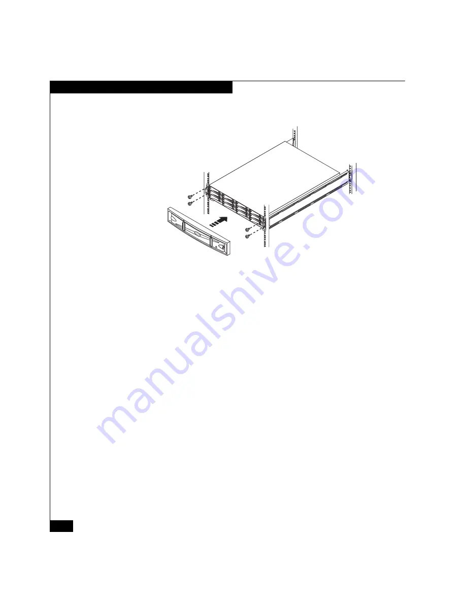
6. Snap the front bezel onto the storage system (Figure 6).

Figure 6

Securing the Chassis and Installing the Front Bezel

What Next?

If you have additional disks to install, continue to the next section, 

Installing Additional Disks

 (page 25).

If you do 

not 

have additional disks to install:

For an AX100SC (single-SP) storage system, go to 

Connecting ac 

Power to an AX100SC Storage System

 (page 32).

For an AX100 (dual-SP) storage system, go to 

Connecting ac Power 

to an AX100 Storage System

 (page 36).

EMC2935

Summary of Contents for EMC2 AX100 Series

Page 1: ...g or Updating the HBA Driver 8 Installing PowerPath on the Server 10 Installing the Navisphere Server Utility 17 Installing the UPS AX100 Only 18 Unpacking the Storage System 19 Installing the Storage System 21 Installing Additional Disks 25 Connecting ac Power to an AX100SC Storage System 32 Connecting ac Power to an AX100 Storage System 36 Connecting the Storage System Management Ports 41 Initia...

Page 2: ...ring an Existing Storage System 62 Preparing Virtual Disks to Receive Data 65 Sending Solaris Disk Information to the Storage System 67 Verifying Your Configuration 68 AX100 Support Website The AX100 support website contains the storage system release notes and the most recent versions of documents and of the interactive troubleshooting trees For information on accessing the AX100 support website ...

Page 3: ...s storage system that is already connected to a server and configured for storage Host A computer that is or will be connected to an AX Series storage system This computer is called either a management host or a server depending on how it is or will be connected to the storage system Management host A host from which you manage AX Series storage systems It must be on the same LAN as the storage sy...

Page 4: ...figuration planning worksheets in Planning Your AX100 Series Fibre Channel Storage System Configuration This guide is in the Plan section on the AX100 support website and on the AX100 Series Documentation CD For a new storage system installation you need An AX100SC or AX100 storage system and the power cord s rails and CDs that ship with it For an AX100 storage system dual SP system an uninterrupt...

Page 5: ... the storage system This server must have all required updates such as hot fixes or patches installed For supported hosts and required updates refer to Supported Configurations in the Technical descriptions section on the AX100 support website One or more supported Sun or QLogic Fibre Channel host bus adapters HBAs which may already be installed in the server These adapters must have the latest su...

Page 6: ...efore You Start To complete this procedure you need one or more supported Sun or QLogic Fibre Channel HBAs with the latest supported BIOS and driver For information on supported HBAs BIOS and drivers refer to Supported Configurations in the Technical descriptions section on the AX100 support website Never mix Fibre Channel HBAs from different vendors in the same server Install HBAs CAUTION HBAs ar...

Page 7: ...age remove it b Locate an empty PCI bus slot c Remove the filler panel from the slot and save it d If your server has a low profile replace the mounting bracket on the HBA bracket with the low profile mounting bracket provided with your HBA e Carefully align the HBA with the slot and then firmly and evenly press the HBA into the slot f Secure the HBA to the slot with the screw or clip from the fil...

Page 8: ... of a supported HBA driver You can download the latest supported version and instructions for installing it from the HBA vendor s website Sun website http wwws sun com software download allproducts html On this site find the latest supported version of the Sun StorEdge SAN driver QLogic HBA website http www qlogic com go emc_approved The HBA driver is also on the installation CD that ships with th...

Page 9: ...lling any updates reboot the server 3 Install the driver following the instructions on the HBA vendor s website 4 If you installed the QLogic HBA driver set the parameters in the kernel drv qla2xxx conf file to the values required for PowerPath as described in the HBA driver instructions 5 Reboot the server when the installation program prompts you to reboot Some driver updates may require you to ...

Page 10: ...isting storage system that is one already connected to another server go to Connecting the Storage System to the Server page 50 Before You Start To complete this procedure you need to Locate the PowerPath for Solaris CD that shipped with the storage system In the etc system file make sure the timeout value is set to 60 seconds This minimizes path failover time without compromising online storage s...

Page 11: ...ons that use PowerPath if you are upgrading from PowerPath 4 0 2 or later For example unmount all file systems mounted on PowerPath pseudo devices If you do not stop these applications uninstalling PowerPath 4 0 2 or later in preparation for the upgrade will abort with a message indicating that PowerPath pseudo devices are still in use If this happens you must either stop applications using PowerP...

Page 12: ...s that execute with super user permission during the installation enter y to continue with deinstallation 3 Insert the PowerPath CD into the CD drive 4 If the CD does not mount automatically mount it manually with the mount command For example to mount the CD on cdrom cdrom0 enter mount F hsfs r dev dsk cxtydzs0 cdrom cdrom0 where x y and z are values specific to the host s CD drive Example mount ...

Page 13: ... installation enter y The screen displays information about the installation If you are upgrading from 3 0 x and the display indicates that the configuration files failed your custom configuration is no longer available after the installation If any of your applications are configured with PowerPath pseudo devices you must reconfigure those applications Refer to Installing and Configuring emcpower...

Page 14: ... upgrade If the sd or ssd driver does not exist on the server you see one of the following messages during boot WARNING forceload of drv sd failed or WARNING forceload of drv ssd failed You can safely ignore this warning Verify the PowerPath Installation 1 Verify that PowerPath is installed properly on the server pkginfo l EMCpower You should see output similar to this PKGINST EMCpower NAME EMC Po...

Page 15: ... Ext 4 3 0 58 7848e000 250c8 1 emcpdpm PV DPM Ext 4 3 0 59 781f5a95 273 1 emcpioc PP PIOC 4 3 0 Verify That PowerPath Commands Are in Your Path Check that the PowerPath commands are in your path PowerPath installation modifies the etc profile and etc login files to run the PowerPath setup scripts which modify the PATH LD_LIBRARY_PATH LD_LIBRARY_PATH_64 and MANPATH variables on the server These cha...

Page 16: ...e that accompanies the patch What Next For information on using PowerPath refer to PowerPath in Action in the Technical descriptions section on the AX100 support website or the AX100 Series Documentation CD If you are connecting the server to a new AX100SC single SP storage system go to Unpacking the Storage System page 19 If you are connecting the server to a new AX100 dual SP storage system go t...

Page 17: ... the storage system Before You Start To complete this procedure you need the AX Series Server Support CD that shipped with the storage system Install the Server Utility 1 Insert the AX Series Server Support CD into the server s CD drive if it is not already inserted 2 Log in to the server as superuser root 3 Start the installation program cd cdrom cdrom0 pkgadd d HOSTUTLA pkg 4 At the prompt to se...

Page 18: ...tandard cabinet rack The UPS is for dual SP storage systems only Before You Start To complete this procedure you need a UPS and the cables and the mounting kit that shipped with it Install a UPS in a Cabinet 1 Unpack the UPS and save the packaging 2 Install the UPS in the cabinet as described in the documentation provided with the UPS CAUTION The UPS ships with the battery cable disconnected Be su...

Page 19: ...ed 0 2 AX100SC single SP storage system and 0 3 AX100 dual SP system are preloaded with storage system software according to their slot assignment before shipment Do not move a preloaded disk from its assigned slot to another slot Doing so causes the storage system to function improperly Remove a preloaded disk only to replace it Figure 1 Location of Disks 0 3 2 Locate and record the serial number...

Page 20: ...20 AX100 Series Installing a Fibre Channel Storage System with a Direct Connection to a Solaris Server Unpacking the Storage System Figure 2 Serial Number Location HW S N XXX 000NNNNNNNN EMC3030 ...

Page 21: ...stem Install the Storage System in a Cabinet 1 Refer to Figure 3 as you install each rail in the cabinet a From the front of the cabinet insert the alignment pins in the rear channel of the cabinet Note that the pins insert in the 1 2 inch space between channel holes marked by a slash mark in some cabinets b Pull the adjustable rail forward and attach it with two screws to the inside of the front ...

Page 22: ...ch NEMA Cabinet 2 If the plastic front bezel is attached remove it 3 Remove the four screws that are secured with washers and nuts to black plastic latch brackets and discard the washers and nuts Figure 4 Figure 4 Removing the Latch Bracket Screws Washers and Nuts Alignment Pins EMC2829 Adjustable Rail Right Front Right Rear Screw 2 Mounting Rail Screw 2 Alignment Pin 2 Mounting Rail EMC3035 ...

Page 23: ... from another person 4 From the front of the cabinet slide the storage system onto the rails so that the cutouts in the rear of the chassis fit into the tabs on the back of each rail Figure 5 If the chassis does not slide all the way into the cabinet you may need to further loosen the screws that hold the rear of the rails in place then adjust the rail to allow the tabs to fit into the cutouts Fig...

Page 24: ...e Chassis and Installing the Front Bezel What Next If you have additional disks to install continue to the next section Installing Additional Disks page 25 If you do not have additional disks to install For an AX100SC single SP storage system go to Connecting ac Power to an AX100SC Storage System page 32 For an AX100 dual SP storage system go to Connecting ac Power to an AX100 Storage System page ...

Page 25: ...n you replace or install FRUs you can inadvertently damage the sensitive electronic circuits in the equipment by simply touching them Electrostatic charge that has accumulated on your body discharges through the circuits If the air in the work area is very dry running a humidifier in the work area will help decrease the risk of ESD damage Follow the procedures below to prevent damage to the equipm...

Page 26: ...suring that your body and the subassembly are at the same electrostatic potential These procedures are not a substitute for the use of an ESD kit Follow them only in the event of an emergency Before touching any FRU touch a bare unpainted metal surface of the cabinet or storage system Before removing any FRU from its antistatic bag place one hand firmly on a bare metal surface of the storage syste...

Page 27: ...ceding section Handling FRUs page 25 Always wear a properly attached ESD wristband when removing or replacing a disk module Place modules on a soft antistatic surface such as an industry standard antistatic foam pad or the container used to ship the module Never place a disk module directly on a hard surface Never hit modules stack modules or allow them to tip over or fall Avoid touching any expos...

Page 28: ...ront bezel and gain access to the disk modules Figure 7 1 Insert the key that shipped with your storage system into the bezel lock and turn it to release the lock 2 Press the two latch buttons on the bezel surface toward each other to release the bezel from the cabinet 3 Pull the bezel off the cabinet and put it on a clean static free surface Figure 7 Unlocking and Removing the Front Bezel EMC2937...

Page 29: ...m with a Direct Connection to a Solaris Server 29 Installing Additional Disks Remove a Disk Filler Module Locate the slot where you want to install the disk module and remove the filler module Figure 8 Figure 8 Removing a Disk Filler Module EMC2810 Filler ...

Page 30: ...r wrist and the storage system see the precautions on page 26 2 Align the module with the guides in the slot 3 Gently push the module completely into the slot Figure 9 To ensure that the module seats completely push in on the disk label as you engage the latch Figure 9 Installing a Disk Module The disk module s Active light flashes to indicate the disk s spin up sequence EMC2812 Label Push Here Di...

Page 31: ...bezel with the storage system 2 Gently push the bezel into place on the cabinet until it latches 3 Secure the bezel by turning the key in the lock Figure 10 Installing and Locking the Front Bezel What Next For an AX100SC single SP storage system continue to Connecting ac Power to an AX100SC Storage System page 32 For an AX100 dual SP storage system go to Connecting ac Power to an AX100 Storage Sys...

Page 32: ...ped with the storage system Connect ac Power to the AX100SC Storage System CAUTION Do not connect the power cord to an ac power source until the storage system is installed in the cabinet The storage system powers up as soon as it is connected to an ac source As you perform the procedure below refer to Figure 11 1 Plug a storage system power cord into the power connector on the power supply in the...

Page 33: ...ins to power up BIOS POST and operating system boot The green power lights LEDs on the front and back of the storage system turn on and remain on as long as power is applied to the storage system Figure 12 The amber SP Boot Fault light flashes to indicate powerup progress The Disk Activity lights on the front of the storage system light intermittently as the disks spin up and disk I O begins EMC29...

Page 34: ...es Documentation CD Figure 12 AX100SC Storage System Lights LEDs If the amber System Fault light is on after powerup a fault exists somewhere in the storage system If the amber light specific to a power supply SP or disk is on then that part is faulted CAUTION Press the power button only briefly to power up the storage system Pressing the power button for more than four seconds while the storage s...

Page 35: ...m takes a full minute to power down after you press the power button So after powering down the storage system wait one minute before powering it on again If storage system power is turned off by the power button or by a software shutdown you must press the power button to re apply power If you power down the storage system by unplugging the power cord the storage system powers up as soon as it is...

Page 36: ... accessory box to connect the UPS serial cable to the storage system The ac power cables appropriate to your power source These cables shipped with the storage system Connect the UPS Serial Cable to the AX100 Storage System CAUTION Be sure to use the unique serial cable supplied with your UPS a standard null modem or other service serial cable may look identical but will not work You may need to a...

Page 37: ...wer connector on both power supplies in the storage system 2 Secure each power cord with the retention bail at the connector The retention bail prevents the power cord from pulling out of the connector and causing the storage system to power down unexpectedly 3 Plug each storage system power cord into an ac power source as follows Do not connect more than one power supply to the UPS a Plug the sto...

Page 38: ...r to an AX100 Storage System Figure 13 Connecting ac Power to an AX100 Storage System EMC2879a Retention Bail To UPS To PDU Power ON I OFF O ON I OFF O ON I OFF O ON I OFF O ON I OFF O ON I OFF O EMC2947 UPS UPS Serial Cable Shipped with UPS AX100 RJ45 DB9 Adapter Cable 110V or 230V Power Cable Appropriate to Power Source ...

Page 39: ...front of the storage system light intermittently as the disks spin up and disk I O begins When powerup is complete usually in 5 6 minutes the SP Boot Fault light goes off If the storage system does not power up within several minutes refer to the Troubleshoot section on the AX100 support website or the AX100 Series Documentation CD Figure 14 AX100 Storage System Lights LEDs If the amber System Fau...

Page 40: ...System For an orderly storage system shutdown that protects your cache data use the storage system power button not the UPS power switch The storage system takes a full minute to power down after you press the power button So after powering down the storage system wait one minute before powering it on again If storage system power is turned off by the power button or by a software shutdown you mus...

Page 41: ...ize it from a host which can be a server connected to the same network subnet as the storage system management ports The management ports are located on the rear of the chassis and labeled 10 100 Before You Start To complete this procedure you need a standard CAT 5 or higher LAN cable for the management port on each storage system SP that you will connect to the 10 100 LAN Cable the Storage System...

Page 42: ...with a Direct Connection to a Solaris Server Connecting the Storage System Management Ports Figure 15 Storage System LAN Connections AX100 Shown EMC3040 UPS Serial 10 100 Management LAN Port Serial 10 100 Management LAN Port CAT 5 Cables Management 10 100 LAN ...

Page 43: ...mplete this procedure you need The completed configuration planning worksheets from Planning Your AX100 Series Fibre Channel Storage System Configuration in the Plan section on the AX100 support website or the AX100 Series Documentation CD The storage system serial number located on a label on the back of the chassis see below A static IP address for each storage processor in the storage system ex...

Page 44: ...the storage system 2 As superuser root install the Navisphere Storage System Initialization Utility cd cdrom cdrom0 pkgadd d INITOOL pkg 3 At the prompt to select the packages to process enter 1 to select INITOOL 4 At the prompt about scripts that execute with super user permission during the installation enter y The screen displays information about the installation 5 When installation is complet...

Page 45: ...isible from the front of the storage system must be off Figure 16 Figure 16 Storage System Lights LEDs 2 As superuser root start the Navisphere Storage System Initialization Utility cd opt Navisphere bin naviinittool 3 Read the license agreement and enter y to accept it The utility automatically scans the subnet for AX100 Series storage systems When this storage system discovery operation is compl...

Page 46: ...Storage System Management Ports section of the completed storage system configuration planning worksheet follow the instructions on the screen to set the following management user account settings for the storage system Storage Processor A IP IP address for SP A management port Storage Processor B IP IP address for SP B management port Subnet Mask Subnet mask associated with the LAN to which the s...

Page 47: ...ess for the first time or changed an SP IP address the utility reboots the storage system and the SP Boot Fault light on the back of each SP starts blinking Figure 17 The reboot takes several minutes to complete When it is completed the SP Boot Fault light on each SP stops blinking and remains off Figure 17 SP Boot Fault and Power Supply Fault Lights AX100 Shown FE 0 FE 1 FE 0 FE 1 Power SP A Boot...

Page 48: ...age system 2 Enter the IP address of an SP in the storage system This address is the one you assigned when you initialized the storage system If Navisphere Express does not open make sure that the storage system is not rebooting When the reboot is complete the SP Boot Fault light on the back of each SP is off and not blinking If the storage system is not rebooting and Navisphere Express still does...

Page 49: ...er shutting down the storage system wait about two minutes for the storage system to power down 2 Press the power button and hold it down for one second after the green Power light comes on Figure 18 a total of about four to five seconds Figure 18 Storage System Power Button and Light LED FE 0 FE 1 FE 0 FE 1 Power LED EMC2928e SP B SP A Power On Off Button Rear AX100 ...

Page 50: ...e following precautions when handling them Keep the covers on all optical cables until you are ready to insert them Avoid tight bends If you need to make a 90º bend do it over 6 to 12 inches Do not use optical cables to support weight including their own unsupported weight if they are long Do not pull long runs of cable instead lay the cable in place or pull only a few feet at a time Place the cab...

Page 51: ...tical connector on the HBA and from the free end of the optical cable and plug the cable into the HBA connector 3 For each additional FE port you want to connect to an HBA repeat steps 1 and 2 Figure 19 Storage System Front End FE and Optical Cable Connectors AX100 Shown What Next If the server has one or more Sun HBAs connected to the storage system continue to Configuring Sun HBAs page 52 If the...

Page 52: ...ry connected configured ok ac0 bank1 memory connected configured ok ac1 bank0 memory connected configured ok ac1 bank1 memory connected configured ok c1 scsi bus connected configured unknown c1 dsk c1t6d0 CD ROM connected configured unknown c3 scsi bus connected unconfiguredunknown c4 scsi bus connected unconfiguredunknown c5 fc fabric connected unconfiguredunknown c6 fc fabric connected unconfigu...

Page 53: ...te on the storage systems connected to the server Adding entries for extra virtual disks LUNs does not cause any problems If you do not know how many virtual LUNs you will create you should add extra entries Before editing the current kernel drv sd conf file make a copy of it just in case the file is lost or errors are made When editing the file follow these precautions Do not delete any original ...

Page 54: ...arget 0 and SP B target 1 of a storage system 3 After you add entries for all of the virtual disks LUNs save the kernel drv sd conf file 4 Reboot the server so that the HBAs can see the SPs reboot r name sd class scsi target 0 lun 0 name sd class scsi target 0 lun 1 name sd class scsi target 0 lun 2 name sd class scsi target 0 lun 3 name sd class scsi target 0 lun 4 name sd class scsi target 0 lun...

Page 55: ...ty does not start the storage system may still be rebooting When the reboot is complete the SP Boot Fault light on the back of each SP is off and not blinking If the reboot is complete try running the utility again 2 In the Server Utility enter 1 to select Update Server Information The utility automatically scans for connected AX100 Series storage systems and displays a list of the ones it finds 3...

Page 56: ...e on the server or on any host on the same LAN as the storage system 2 Enter the IP address of an SP in the storage system The IP address is one you assigned when you initialized the storage system from the Storage Management Ports section of the planning guide If Navisphere Express does not open make sure that the storage system is not rebooting When the reboot is complete the SP Boot Fault light...

Page 57: ...e unregistered register the HBA with the storage system by running the Navisphere Server Utility as described in Registering the Server with the Storage System page 55 If the status is Inactive either the physical connection between the HBA and the storage system is faulty or the storage system is not powered up Go to the Troubleshoot section on the AX100 support website or the AX100 Series Docume...

Page 58: ...t Navisphere Express If It Is Not Already Running 1 Open an Internet browser such as Internet Explorer or Netscape on the server or on any host on the same LAN as the storage system 2 Enter the IP address of an SP in the storage system This address is the one you assigned when you initialized the storage system If Navisphere Express does not open make sure that the storage system is not rebooting ...

Page 59: ...ks and a RAID 1 0 must include at least two disks The storage system supports a maximum of six disk pools To create a disk pool In the Navisphere Express navigation pane under Manage click Disk Pools For details on creating a disk pool use the Navisphere Express Help Center For an AX100 dual SP storage system you should create at least two disk pools since the software assigns each disk pool you c...

Page 60: ...r If you want to connect additional servers to the storage system you can create virtual disks for them now You have to wait until the servers are connected and registered before you can assign these virtual disks to them 5 Assign one or more virtual disks to the server To send data to or receive data from the virtual disks you must assign the virtual disks to a server To assign a virtual disk to ...

Page 61: ...nt Notification For details on configuring the storage system to send E mail messages use the Navisphere Express Help Center 8 On the Solaris server scan for the virtual disks devfsadm C 9 Use the format command to verify that Solaris recognizes the virtual disks LUNs If Solaris does not recognizes the virtual disks reboot the server reboot r 10 Configure PowerPath etc opt emcpower powercf q power...

Page 62: ...on CD Start Navisphere Express If It Is Not Already Running 1 Open an Internet browser such as Internet Explorer or Netscape on the server or on any host on the same LAN as the storage system 2 Enter the IP address of an SP in the storage system This address is the one you assigned when you initialized the storage system If Navisphere Express does not open make sure that the storage system is not ...

Page 63: ...ccording to their slot assignment Do not move any disk marked 0 through 3 from its assigned slot Remove it only to replace the disk module Part of the space on these disks is reserved or preloaded with system data and as a result is not available for your data If you combine operating system disks in a disk pool with other disks each of the other disks loses space for your data equal to the system...

Page 64: ... column of the server s row If you do not see virtual disks go to the Troubleshoot section on the AX100 support website or the AX100 Series Documentation CD 6 On the Solaris server scan for the virtual disks devfsadm C 7 Use the format command to verify that Solaris recognizes the virtual disks LUNs If Solaris does not recognizes the virtual disks reboot the server reboot r 8 Configure PowerPath e...

Page 65: ...0d2 If you do not know the disk name enter format and from the Available Disk Selections menu select the disk number 2 If you are prompted to label the disk enter y for yes 3 From the main Format menu enter partition and press Enter to modify the partition 4 From the main Partition menu enter label and press Enter to label the disk 5 Enter q to exit the partition menu 6 From the main Format menu e...

Page 66: ...unts the partition dev dsk c2t0d0s0 onto the mount point temp To verify that the files system was mounted enter df k This mount command is required every time the server is rebooted If preferable you can have the file system mount automatically at boot time by adding this mount command to the etc vfstab file Data can now be written to and read from the file system Unmount a File System 1 Make sure...

Page 67: ...art the Server Utility On the Solaris server enter opt Navisphere bin axnaviserverutil If the server utility does not start the storage system may still be rebooting When the reboot is complete the SP Boot Fault light on the back of each SP is off and not blinking The utility automatically scans for connected AX100 Series storage systems and displays a list of the ones it finds Register the Server...

Page 68: ...ils page displays the volume or file system and device name for the virtual disk Verifying Your Configuration Read this section for all configurations Before you store data on virtual disks you should use the procedure below to verify that The server can send data to the storage system You can download an I O simulator Iometer for writing data to the storage system from the following website http ...

Page 69: ...tual disk by writing data to it 6 Identify the HBA sending data to the virtual disk by viewing the output of the powermt display dev x every 2 command and disconnect the cable to that HBA 7 View the output of the powermt display dev x every 2 command and verify that The state of the uncabled paths becomes dead Data continues to be sent on the remaining path s to the virtual disk indicating that th...

Page 70: ...4 2005 EMC Corporation All Rights Reserved EMC believes the information in this publication is accurate as of its publication date The information is subject to change without notice THE INFORMATION IN THIS PUBLICATION IS PROVIDED AS IS EMC CORPORATION MAKES NO REPRESENTATIONS OR WARRANTIES OF ANY KIND WITH RESPECT TO THE INFORMATION IN THIS PUBLICATION AND SPECIFICALLY DISCLAIMS IMPLIED WARRANTIE...

Reviews: