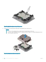
NOTE:
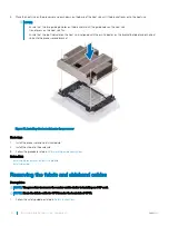
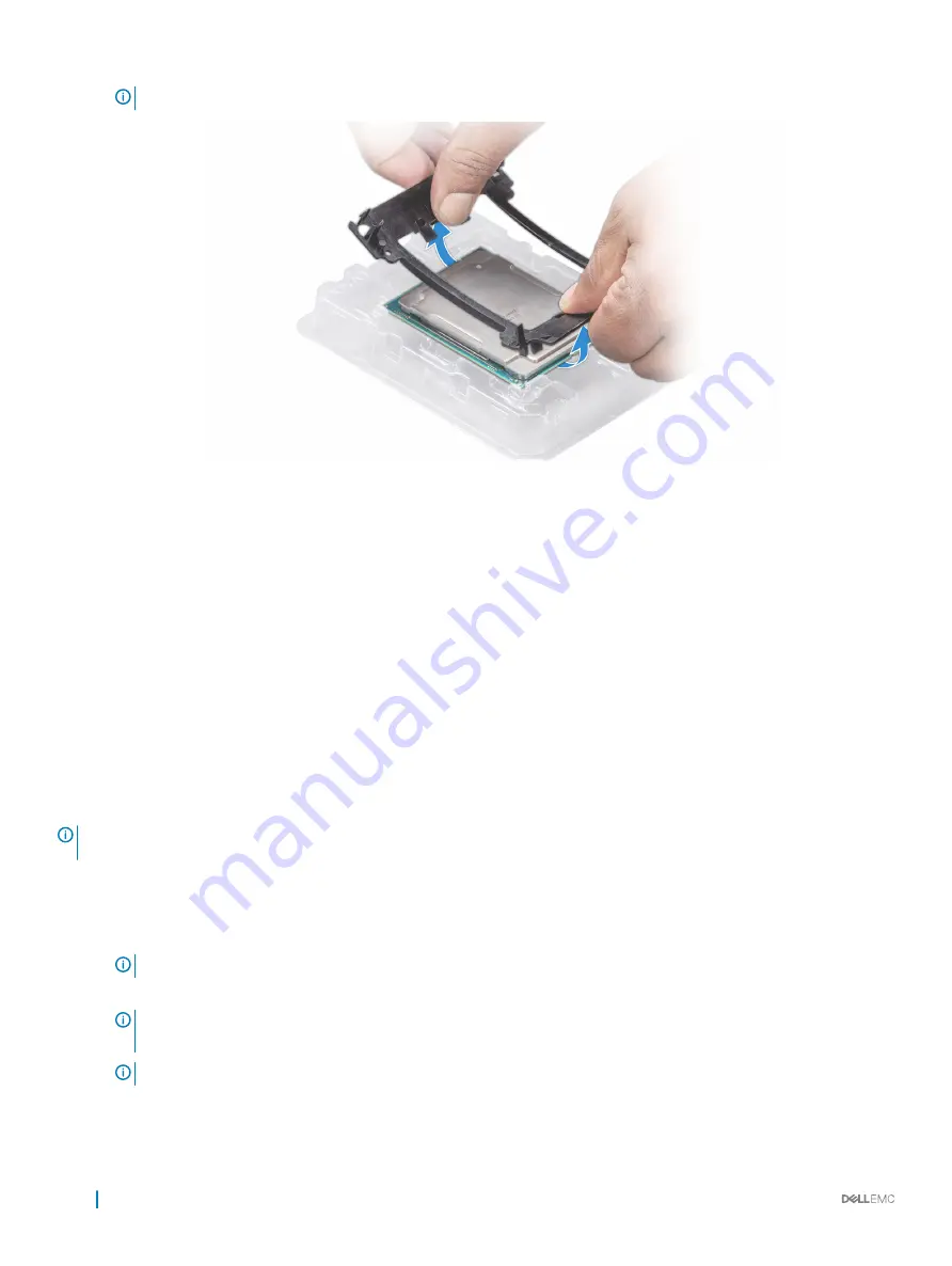
Ensure that the processor and the bracket are placed in the tray after you remove the heat sink.
Figure 35. Removing the processor bracket
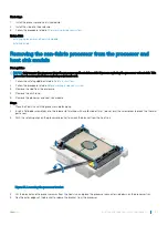
Next step
Install the non-fabric processor into the processor and heat sink module.
Related link
Removing a sled
Removing the air shroud
Removing a processor and heat sink module
Installing the non-fabric processor into a processor and heat sink module
Installing the non-fabric processor into a processor and heat
sink module
Prerequisite
NOTE:
In a sled which has been configured with mixed CPUs – a fabric processor installed in the CPU2 socket and a non-fabric
processor installed in the CPU1 socket, you must connect the external Omnipath link cables to Port 2 on the OCP carrier card.
Follow the safety guidelines listed in
Steps
1
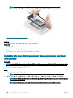
Place the processor in the processor tray.
NOTE:
Ensure that the pin 1 indicator on the processor tray is aligned with the pin 1 indicator on the processor.
2
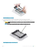
Flex the outer edges of the bracket around the processor ensuring that the processor is locked into the clips on the bracket.
NOTE:
Ensure that the pin 1 indicator on the bracket is aligned with the pin 1 indicator on the processor before placing
the bracket on the processor.
NOTE:
Ensure that the processor and the bracket are placed in the tray before you install the heat sink.
88
Installing and removing system components
Summary of Contents for EMC PowerEdge C6420
Page 1: ...Dell EMC PowerEdge C6420 Regulatory Model E43S Series Regulatory Type E43S001 ...
Page 8: ...Figure 1 Supported configurations for PowerEdge C6420 8 PowerEdge C6420 overview ...
Page 64: ...Figure 12 Removing a sled 64 Installing and removing system components ...
Page 66: ...Figure 14 Installing a sled 66 Installing and removing system components ...


