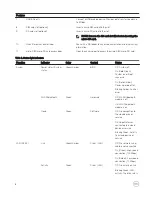


F
Function
Indicator
Color
Control
Status
related to packet
density.
NOTE: The power/system status light may operate differently during different boot-up scenarios. For example, when a
USB script file is run during boot-up.
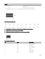
Table 5. Power connector pin definition details
Pin
Signal
Function
1
DC+
12–57 VDC power
2
DC–
Ground
3
IG
9–32 VDC ignition
NOTE: Pin 3 (IG) is connected to the vehicle's ignition status indicator (optional) or a wake pin. A voltage of more than 9
V on the signal indicates that the vehicle’s engine is running. The Ignition or Wake pin is used to prevent the draining of
the vehicle battery when the vehicle is turned off for an extended amount of time.
NOTE: The IG signal can be used to gracefully shutdown or enter low-power sleep state when the vehicle is turned off
(battery powered). It can also be used for turning on the Edge Gateway when the vehicle starts.
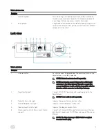
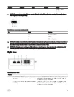
Right view
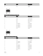
Table 6. Right view—3001
Features
1
RS-232/RS-422/RS-485 port one (configurable in
the BIOS)
Connect a RS-232/RS-422/RS-485 cable to the Edge Gateway.
Provides data transfer speeds up to 1 Mbps in RS-232 mode and
12 Mbps in RS-422/RS-485 mode.
2
RS-232/RS-422/RS-485 port two (configurable in
the BIOS)
Connect a RS-232/RS-422/RS-485 cable to the Edge Gateway.
Provides data transfer speeds up to 1 Mbps in RS-232 mode and
12 Mbps in RS-422/RS-485 mode.
9
Summary of Contents for Edge 3001
Page 12: ...12 ...
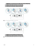
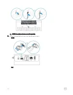
Page 29: ...7 7 Tighten the screws to secure the assembly to the wall 29 ...
Page 36: ...5 5 Tighten the screws to secure the assembly to the wall 36 ...
Page 49: ...49 ...