background image

1.

Ensure that all cables are connected, and fold cables out of the way.  


2.

Ensure that no tools or extra parts are left inside the computer.  


3.

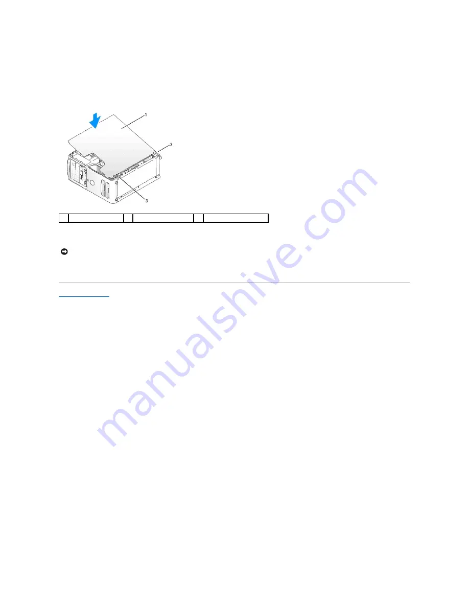
Align the bottom of the cover with the tabs located along the bottom edge of the computer.  


4.

Using the tabs as leverage, rotate the cover downward and press down to close it.  


5.

Ensure that the cover is seated correctly before moving it to the upright position.  


6.

Connect your computer and devices to electrical outlets, and turn them on.  
 

Back to Contents Page


computer cover 

back of computer 

bottom hinge tabs 


NOTICE: 

To connect a network cable, first plug the cable into the network device and then plug it into the computer.

Summary of Contents for E521 - Dimension Motherboard UW457 0UW457

Page 1: ...in this text Dell the DELL logo and Dimension are trademarks of Dell Inc Microsoft and Windows are registered trademarks of Microsoft Corporation AMD Athlon and Sempron are trademarks of Advanced Micro Devices Inc Other trademarks and trade names may be used in this document to refer to either the entities claiming the marks and names or their products Dell Inc disclaims any proprietary interest i...

Page 2: ...ector Use the headphone connector to attach headphones and most kinds of speakers 8 LAN indicator light This light indicates that a LAN local area network connection is established 9 diagnostic lights 4 Use the lights to help you troubleshoot a computer problem based on the diagnostic code For more information see Diagnostic Lights 10 hard drive activity light The hard drive activity light is on w...

Page 3: ...I Express cards 1 link integrity light l Green A good connection exists between a 10 Mbps network and the computer l Orange A good connection exists between a 100 Mbps network and the computer l Off The computer is not detecting a physical connection to the network 2 network adapter connector To attach your computer to a network or broadband device connect one end of a network cable to either a ne...

Page 4: ...use the connector on the card 7 microphone Use the pink connector to attach a personal computer microphone for voice or musical input into a sound or telephony program On computers with a sound card the microphone connector is on the card 8 side surround connector Use the silver connector to provide enhanced surround audio for computers with 7 1 speakers On computers with a sound card the micropho...

Page 5: ...l power but an internal power problem might exist Ensure that the voltage selection switch is set to match the AC power at your location if applicable l If the power light is steady amber a device might be malfunctioning or incorrectly installed Remove and then reinstall the memory modules see Memory Remove and then reinstall any cards see Cards Remove and then reinstall the graphics card if appli...

Page 6: ...estart the computer No memory modules are detected l If you have two or more memory modules installed remove the modules reinstall one module see Installing Memory and then restart the computer If the computer starts normally reinstall an additional module Continue until you have identified a faulty module or reinstalled all modules without error l If available install properly working memory of t...

Page 7: ...ailure See Drive Problems in your Owner s Manual No boot device detected Insert a bootable floppy disk or CD Invalid configuration information please run SETUP program Enter system setup and correct the computer configuration information see Entering System Setup Keyboard failure See Keyboard Problems in your Owner s Manual Memory allocation error 1 Turn off the computer wait 30 seconds and then r...

Page 8: ... in your Owner s Manual Shutdown failure Run the Dell Diagnostics Unexpected interrupt in protected mode Run the Dell Diagnostics WARNING Dell s Disk Monitoring System has detected that drive 0 1 on the primary secondary EIDE controller is operating outside of normal specifications It is advisable to immediately back up your data and replace your hard drive by calling your support desk or Dell If ...

Page 9: ...m You may need to install drivers if you l Upgrade your operating system l Reinstall your operating system l Connect or install a new device Identifying Drivers Option Function Express Test Performs a quick test of devices This test typically takes 10 to 20 minutes and requires no interaction on your part Run Express Test first to increase the possibility of tracing the problem quickly Extended Te...

Page 10: ...rformance and Maintenance 3 Click System 4 In the System Properties window click the Hardware tab 5 Click Device Manager 6 Right click the device for which the new driver was installed then click Properties 7 Click the Driver tab 8 Click Roll Back Driver Manually Reinstalling Drivers 1 After copying the required driver files to your hard drive click the Start button and right click My Computer 2 C...

Page 11: ...ooter to resolve the incompatibility To resolve incompatibilities using the Hardware Troubleshooter 1 Click Start then click Help and Support 2 Type hardware troubleshooter in the Search field then click the arrow to start the search 3 Click Hardware Troubleshooter in the Search Results list 4 In the Hardware Troubleshooter list click I need to resolve a hardware conflict on my computer and then c...

Page 12: ...ress and hold the power button for 4 seconds Before Working Inside Your Computer Use the following safety guidelines to help protect your computer from potential damage and to help ensure your own personal safety 1 Turn off your computer See Turning Off Your Computer NOTICE To avoid losing data save and close any open files and exit any open programs before you turn off your computer CAUTION Befor...

Page 13: ...ents Page NOTICE To disconnect a network cable first unplug the cable from your computer and then unplug it from the network port or device NOTICE Before touching anything inside your computer ground yourself by touching an unpainted metal surface such as the metal at the back of the computer While you work periodically touch an unpainted metal surface to dissipate any static electricity that coul...

Page 14: ...s side with the computer cover facing up 3 Pull back the cover release latch located on the top panel CAUTION Before you begin any of the procedures in this section follow the safety instructions in the Product Information Guide CAUTION To guard against electrical shock always unplug your computer from the electrical outlet before removing the cover CAUTION When working inside the computer be awar...

Page 15: ... beginning with connectors DIMM_1 and DIMM_2 then connectors DIMM_3 and DIMM_4 If a single DIMM is installed you must install it in connector DIMM_1 l For best performance memory modules should be installed in pairs of matched memory size speed and technology If the memory modules are not installed in matched pairs the computer will operate but with a slight reduction in performance See the label ...

Page 16: ...el B matched pair of memory modules in connectors DIMM_3 and DIMM_4 black securing clips NOTICE If you remove your original memory modules from the computer during a memory upgrade keep them separate from any new modules that you may have even if you purchased the new modules from Dell If possible do not pair an original memory module with a new memory module Otherwise your computer may not start ...

Page 17: ...d damage to the memory module press the module straight down into the connector while you apply equal force to each end of the module NOTICE To connect a network cable first plug the cable into the network device and then plug it into the computer CAUTION Before you begin any of the procedures in this section follow the safety instructions in the Product Information Guide NOTICE To prevent static ...

Page 18: ...or is hinged and will remain in the open position 4 If you are installing a new card remove the filler bracket to create a card slot opening Then continue with step 6 5 If you are replacing a card that is already installed in the computer remove the card If necessary disconnect any cables connected to the card Grasp the card by its top corners and ease it out of its connector 6 Prepare the card fo...

Page 19: ...s and turn them on 13 If you installed a sound card a Enter system setup see System Setup go to Onboard Devices and select Integrated Audio and then change the setting to Off b Connect external audio devices to the sound card s connectors Do not connect external audio devices to the microphone speaker headphone or line in connectors on the back panel 1 alignment bar 2 fully seated card 3 not fully...

Page 20: ...ver 3 Gently push the release tab on the card retention door from the inside to pivot the door open The door is hinged and will remain in the open position 4 If you are removing the card permanently install a filler bracket in the empty card slot opening 5 Close the card retention door by snapping it into place to secure the cards NOTE You can use the integrated NIC and add in NIC adapter at the s...

Page 21: ...e card may be very hot during normal operation Be sure that the heat sink has had sufficient time to cool before you touch the card Installing a PCI Express Card 1 Follow the procedures in Before You Begin 2 Remove the computer cover see Removing the Computer Cover 3 Gently push the release tab on the card retention door from the inside to pivot the door open The door is hinged and will remain in ...

Page 22: ... the connector and press down firmly Ensure that the card is fully seated in the slot 10 Ensure that l The tops of all cards and filler brackets are flush with the alignment bar l The notch in the top of the card or filler bracket fits around the alignment guide 11 If previously removed snap the card retention mechanism into place securing the x16 PCI card 1 PCI Express x16 card 2 securing tab 3 P...

Page 23: ...sition see Installing a PCI Card for an illustration of the card retention door 4 If your computer includes a card retention mechanism to secure the x16 card in place from the top a Pivot the mechanism upward and gently squeeze in on the sides to release the mechanism from the two tab slots holding it in place b Set the retention mechanism aside 5 If you are removing the card permanently install a...

Page 24: ... integrated connector on the back panel of the computer See Back Panel Connectors Drive Panel Removing the Drive Panel 1 Follow the procedures in Before You Begin 2 Remove the computer cover see Removing the Computer Cover 3 Grasping the lever on the sliding plate pull the sliding plate to the right until it snaps into the open position 4 By pushing from the inside and pivoting the drive panel to ...

Page 25: ...ure location Installing the Drive Panel Insert 1 Slide the tab on the left side of the drive panel insert under the center drive panel tab 2 Rotate the drive panel insert into place and snap the drive panel insert tab over the corresponding tab on the drive panel Installing the Drive Panel 1 Follow the procedures in Before You Begin 1 drive panel 2 drive panel insert tab 3 drive panel insert 1 cen...

Page 26: ... optional Media Card Reader l Up to two CD or DVD drives Connect serial ATA hard drives to connectors labeled SATA0 or SATA1 on the system board Connect serial ATA CD or DVD drives to connectors labeled SATA2 or SATA3 on the system board See System Board Components Connecting Drive Cables 1 sliding plate lever 2 sliding plate 3 drive panel 4 drive panel tabs 3 5 side hinges 1 CD DVD drive 2 FlexBa...

Page 27: ... CAUTION Before you begin any of the procedures in this section follow the safety instructions in the Product Information Guide CAUTION To guard against electrical shock always unplug your computer from the electrical outlet before removing the cover NOTICE To avoid damage to the drive do not set it on a hard surface Instead set the drive on a surface such as a foam pad that will sufficiently cush...

Page 28: ...Drive 0 through 3 set the Drive to the correct configuration 6 Replace the computer cover see Installing the Computer Cover 7 Connect computer and other devices to an electrical outlet Installing a Hard Drive 1 Follow the procedures in Before You Begin 2 Remove the computer cover see Removing the Computer Cover 3 Check the documentation for the drive to verify that it is configured for your comput...

Page 29: ...Replace the computer cover see Installing the Computer Cover 9 Connect your computer and devices to electrical outlets and then turn them on See the documentation that came with the drive for instructions on installing any software required for drive operation 10 Check the System Setup for drive configuration changes see Entering System Setup 1 drive 2 hard drive bracket 1 hard drive bracket 2 har...

Page 30: ...n turn them on See the documentation that came with the drive for instructions on installing any software required for drive operation Floppy Drive CAUTION Before you begin any of the procedures in this section follow the safety instructions in the Product Information Guide CAUTION To guard against electrical shock always unplug your computer from the electrical outlet before removing the cover NO...

Page 31: ...s 5 Remove the data cable from the clip on the processor shroud Remove the cable from the computer 6 Slide the drive latch release toward the bottom of the computer and then slide the floppy drive out through the front of the computer 7 If you are not replacing the drive reinstall the drive panel insert see Installing the Drive Panel Insert 8 Replace the computer cover see Installing the Computer ...

Page 32: ...Connect the other end of the data cable to the connector labeled FLOPPY1 on the system board see System Board Components and route the cable through the clip on the processor shroud 8 Check all cable connections and fold cables out of the way to avoid blocking airflow between the fan and cooling vents Insert the floppy data cable into the clip on top of the processor shroud 9 Replace the drive pan...

Page 33: ...ia Card Reader Disconnect the other end of the cable from the USB connector on the system board see System Board Components Remove the cable from any clips and lift out of the computer NOTICE To connect a network cable first plug the cable into the network device and then plug it into the computer CAUTION Before you begin any of the procedures in this section follow the safety instructions in the ...

Page 34: ...vices to electrical outlets and then turn them on Installing a Media Card Reader 1 Follow the procedures in Before You Begin 2 Remove the computer cover see Removing the Computer Cover 3 Remove the drive panel see Removing the Drive Panel 4 If this is a new card reader installation l Remove the drive panel insert see Removing the Drive Panel Insert Remove the four shoulder screws from the drive pa...

Page 35: ... and then turn them on CD DVD Drive Removing a CD DVD Drive 1 Follow the procedures in Before You Begin 2 Remove the computer cover see Removing the Computer Cover 3 Remove the drive panel see Removing the Drive Panel 4 Disconnect the power cable and the CD DVD drive data cable from the back of the drive and the system board 1 Media Card Reader 2 USB cable 3 USB connector CAUTION Before you begin ...

Page 36: ...8 Replace the computer cover see Installing the Computer Cover 9 Connect your computer and devices to electrical outlets and then turn them on 10 Configure the drives in System Setup see Entering System Setup Installing a CD DVD Drive 1 power cable 2 data cable 1 drive release latch 2 sliding plate 3 CD DVD drive NOTE In the event that the replacement or new CD DVD drive does not have shoulder scr...

Page 37: ... the new drive 5 Slide the drive into the drive bay until the drive clicks into position 6 Connect the power cable to the drive 7 Connect the CD DVD data cable to the drive and to the connector on the system board see System Board Components 8 Check all cable connections and fold cables out of the way to avoid blocking airflow between the fan and cooling vents 9 Replace the drive panel see Install...

Page 38: ... or equivalent type recommended by the manufacturer Discard used batteries according to the manufacturer s instructions To replace the battery 1 Record all the screens in system setup see System Setup so that you can restore the correct settings in step 9 2 Follow the procedures in Before You Begin 3 Remove the computer cover see Removing the Computer Cover 4 Locate the battery socket see System B...

Page 39: ...ront of the computer by approximately 1 inch 8 Lift the power supply up and out of the computer 9 Lower the replacement power supply into the computer 10 Slide the power supply toward the back of the computer until the release button snaps into the locking position 11 Replace the screws that secure the power supply to the back of the computer chassis 12 Reconnect the DC power cables to the system ...

Page 40: ...ly 6 Rotate the heat sink assembly upward and remove it from the computer Lay the heat sink assembly down on its top with the thermal grease facing upward NOTE Double check all cable connections to make sure they are secure CAUTION Before you begin any of the procedures in this section follow the safety instructions located in the Product Information Guide NOTICE To prevent static damage to compon...

Page 41: ...cessor and socket 1 processor 2 release lever 3 socket NOTICE Be careful not to bend any of the pins when you remove the processor Bending the pins can permanently damage the processor NOTICE After removing the processor be careful not to get any thermal grease on the processor pins Thermal grease on the pins can permanently damage the processor NOTICE Ground yourself by touching an unpainted meta...

Page 42: ...es in the system board c Tighten the two captive screws 10 If previously removed snap the card retention mechanism into place securing the x16 PCI card 1 processor pin 1 indicator 2 processor 3 release lever 4 socket NOTICE To avoid damage ensure that the processor aligns properly with the socket and do not use excessive force when you install the processor NOTICE Ensure that you apply new thermal...

Page 43: ...structions in the Product Information Guide CAUTION To guard against electrical shock always unplug your computer from the electrical outlet before opening the cover CAUTION The heat sink assembly power supply and other components may be very hot during normal operation Be sure that they have had sufficient time to cool before you touch them NOTICE To prevent static damage to components inside you...

Page 44: ... the captive screw on each side of the heat sink assembly NOTICE Take care not to damage the cable connectors and the cable routing clips when sliding the I O panel into the computer CAUTION Before you begin any of the procedures in this section follow the safety instructions in the Product Information Guide CAUTION To guard against electrical shock always unplug your computer from the electrical ...

Page 45: ...tom cover 10 Remove the fan from the computer Installing the Processor Fan When reinstalling the fan ensure that you do not pinch the wires that run between the system board and the fan 1 Place the fan into the computer aligning the fan assembly to the notches in the bottom of the chassis Then slide the fan assembly toward the front of the computer Ensure that the release levers are secure 2 Repla...

Page 46: ...e same location after the board is replaced 6 Disconnect all cables from the system board Note the routing of all cables as you remove them so that you can re route them correctly after installing the new system board 7 Remove the six screws from the system board 8 Remove the two green screws securing the heat sink assembly bracket Note the orientation of the heat sink assembly bracket as you remo...

Page 47: ...ssembly bracket b Rotate the heat sink assembly down towards the computer base and ensure that the two captive screws are properly aligned with the holes in the system board c Tighten the two captive screws 8 Replace any add in cards on the system board 9 Replace the computer cover see Installing the Computer Cover 10 Connect your computer and devices to an electrical outlet and turn them on 11 Ve...

Page 48: ... Using the tabs as leverage rotate the cover downward and press down to close it 5 Ensure that the cover is seated correctly before moving it to the upright position 6 Connect your computer and devices to electrical outlets and turn them on Back to Contents Page 1 computer cover 2 back of computer 3 bottom hinge tabs NOTICE To connect a network cable first plug the cable into the network device an...

Page 49: ...ndows are registered trademarks of Microsoft Corporation AMD Athlon and Sempron are trademarks of Advanced Micro Devices Inc Other trademarks and trade names may be used in this document to refer to either the entities claiming the marks and names or their products Dell Inc disclaims any proprietary interest in trademarks and trade names other than its own September 2006 Rev A00 Back to Contents P...

Page 50: ... to the operating system Computer Information Chipset Nvidia GeForce 6150LE RAID Support RAID 1 Mirroring DMA channels eight Interrupt levels 24 BIOS chip NVRAM 4 Mb NIC Integrated network interface capable of 10 100 communication Video Type Nvidia integrated video DirectX 9 0 Shader Model 3 0 Graphics Processing Unit or optional PCI Express x16 graphics card Audio Type Sigmatel 9227 CODEC 7 1 Cha...

Page 51: ... pin connectors PCI Express x1 one 36 pin connector PCI Express x16 one 164 pin connector Front panel one 40 pin connector Processor one 940 pin connector Memory four 240 pin connectors Power 12V one 4 pin connector Power one 24 pin connector Controls and Lights Front of computer Power button push button Power light green light Blinking green in sleep state solid green for power on state amber lig...

Page 52: ...ting information 90 to 135 V and 180 to 265 V at 50 60 Hz Backup battery 3 V CR2032 lithium coin cell Physical Height 41 4 cm 16 3 inches Width 18 8 cm 7 4 inches Depth 45 7 cm 18 0 inches Weight 12 7 kg 28 0 lb Environmental Temperature Operating 10 to 35 C 50 to 95 F Storage 40 to 65 C 40 to 149 F Relative humidity 20 to 80 noncondensing Maximum vibration Operating 5 to 350 Hz at 0 0002 G2 Hz St...

Page 53: ...t the top the main window the Item Help field on the right and key functions listed on the bottom NOTICE Do not change the settings in system setup unless you are an expert computer user Certain changes can cause your computer to work incorrectly NOTE Keyboard failure may result when a key on the keyboard is held down for extended periods of time To avoid possible keyboard failure press and releas...

Page 54: ...e controller and allows the internal floppy drive read only permission NOTE Operating systems with USB support will recognize USB floppy drives regardless of this setting Drives 0 through 3 On default Enables or disables an ATA or SATA device such as hard drive CD drive or DVD drive On enables the interface so that the device can be used Displays the Controller type ATA or SATA Port number the dri...

Page 55: ...to be assigned and verified Password Changes Unlocked default Determines the interaction between the System password and the Admin password Locked prevents a user without a valid Admin password from being able to modify the System password Unlocked allows a user with a valid System password to modify the system password No Execute On default Enables or disables Execute Disable memory protection te...

Page 56: ...nt Log Allows you to view the Event Log Entries are marked R for Read and U for Unread Mark All Entries Read puts an R to the left of all entries Clear Log clears the Event Log POST Behavior Fast Boot On default When enabled this feature reduces computer startup time by bypassing some compatibility steps l Off does not skip any steps during computer startup l On starts the system more quickly Numl...

Page 57: ...ppropriate Boot Sequence option 4 Press the U or D keys to move the option up or down in the boot sequence 5 Press Enter to Save the changes or Esc to Cancel Clearing Forgotten Passwords 1 Follow the procedures in Before Working Inside Your Computer 2 Remove the computer cover see Removing the Computer Cover NOTE Keyboard failure may result when a key on the keyboard is held down for extended peri...

Page 58: ...Locate the 2 pin CMOS jumper RTCRST on the system board see System Board Components b Remove the jumper plug from the password jumper PSWD pins 1 and 2 c Place the jumper plug on the CMOS jumper RTCRST pins 1 and 2 and wait approximately five seconds d Remove the jumper plug and replace it on the password jumper PSWD pins 1 and 2 4 Replace the computer cover see Installing the Computer Cover 5 Con...

Page 59: ...window appears 6 Click the down arrow to view the Save In menu select Desktop and then click Save The file downloads to your desktop 7 Click Close when the Download Complete window appears The file icon appears on your desktop and is titled the same as the download BIOS update file 8 Double click the file icon on the desktop and follow the on screen instructions Back to Contents Page ...

Page 60: ...1 Service Manual Inside View of Your Computer System Board Components Power Supply DC Connector Pin Assignments Inside View of Your Computer System Board Components 1 floppy drive or Media Card Reader 2 CD or DVD drive 3 power supply 4 system board 5 hard drive ...

Page 61: ...urround center and LFE connectors AUDIO_6_STACK 10 USB connectors 2 USB2_BACK1 11 network connector and USB connectors 2 NIC_USB1 12 real time clock reset jumper RTCRST 13 video connector VIDEO1 14 battery socket BT1 15 Internal USB connector USB1 16 PCI Express x16 connector SLOT1 17 standby power indicator AUX_PWR_LED 18 PCI Express x1 connector SLOT2 19 PCI connector SLOT3 20 PCI connector SLOT...

Page 62: ...VDC Orange 13 3 3VDC SE Orange 14 12 VDC Blue 15 GND Black 16 PWR_PS_ON Green 17 GND Black 18 GND Black 19 GND Black 20 NC NC 21 5 VDC Red 22 5 VDC Red 23 5 VDC Red 24 GND Black Pin Number Signal Name 18 AWG Wire 1 GND Black 2 GND Black 3 12 VADC Yellow 4 12 VADC Yellow Pin Number Signal name 18 AWG Wire 1 3 3 VDC Orange 2 GND Black 3 5 VDC Red 4 GND Black 5 12 VBDC White ...

Page 63: ...Connector P10 Back to Contents Page Pin Number Signal Name 22 AWG Wire 1 5 VDC Red 2 GND Black 3 GND Black 4 12 VADC Yellow Pin Number Signal name 18 AWG Wire 1 12 VBDC White 2 GND Black 3 GND Black 4 5 VDC Red ...

Reviews: