background image

4-28

Dell Dimension V

xxx

 and V

xxx

c Systems Service Manual

7.

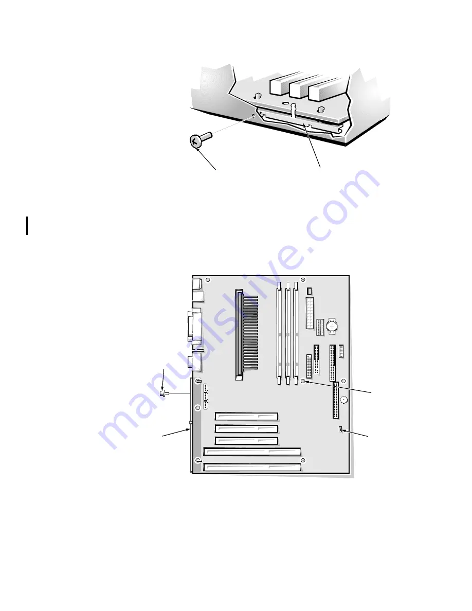
Remove the system-board mounting screw from the back of the computer 
(see Figure 4-26). 

)LJXUH  0RXQWLQJ 6FUHZ DQG %UDFNHW

8. Lift the system board from the three plastic standoffs that secure the sys-

tem board to the chassis (see Figure 4-27). 

9. Carefully lift the system board away from the I/O gasket (see Figure 4-24), and 

remove the board from the computer.

)LJXUH  6\VWHP %RDUG 0RXQWLQJV

back of 
computer

system-board 
mounting screw

system-board 
mounting bracket

system-board 
mounting 
screw

configuration 
jumper J9D3

system-board 
mounting 
bracket

screws (3)

Summary of Contents for Dimension V333

Page 1: ...ZZZ GHOO FRP HOO LPHQVLRQ 9 DQG 9 F 6 VWHPV 6 59 0 18 ...

Page 2: ...entium are registered trademarks and Celeron and MMX are trademarks of Intel Corporation Microsoft Windows and MS DOS are registered trademarks of Microsoft Corporation IBM is a registered trademark of International Business Machines Corporation VESA is a registered trademark of Video Electronics Standards Association Other trademarks and trade names may be used in this document to refer to either...

Page 3: ...emory 1 13 System Board Jumper 1 13 Interrupt Assignments 1 15 DMA Channel Assignments 1 16 Technical Specifications 1 17 KDSWHU DVLF 7URXEOHVKRRWLQJ Initial User Contact 2 1 External Visual Inspection 2 2 Observing the Boot Routine 2 3 Internal Visual Inspection 2 4 Eliminating Resource Conflicts 2 5 Running the Dell Diagnostics 2 6 Getting Help 2 6 KDSWHU LDJQRVWLF RGHV HHS RGHV DQG UURU 0HVVDJH...

Page 4: ...mbly 4 17 Card Guide Assembly 4 18 Control Panel Board 4 19 System Board Components 4 20 Expansion Cards 4 21 DIMMs 4 22 Microprocessor and Heat Sink Assembly 4 23 Replacing the Battery 4 25 System Board 4 26 SSHQGL 6 VWHP 6HWXS 3URJUDP System Setup Screens A 1 Main Screen A 2 Advanced Screen A 3 Peripheral Configuration Submenu A 5 IDE Configuration Submenu A 6 Primary IDE Master Submenu A 8 Disk...

Page 5: ...4 8 Figure 4 8 Upper 3 5 Inch Drive Removal 4 10 Figure 4 9 Lower 3 5 Inch Drive Removal Mini Tower Computer Only 4 11 Figure 4 10 3 5 Inch Diskette Drive Removal 4 12 Figure 4 11 Primary Hard Disk Drive Removal 4 13 Figure 4 12 Secondary Hard Disk Drive Assembly Removal 4 14 Figure 4 13 Secondary Hard Disk Drive Removal 4 15 Figure 4 14 Power Supply Removal 4 16 Figure 4 15 Fan Assembly Removal 4...

Page 6: ...errupt Assignments 1 15 Table 1 4 DMA Channel Assignments 1 16 Table 1 5 Technical Specifications 1 17 Table 3 1 Diagnostic Indicator Codes 3 2 Table 3 2 POST Beep Codes 3 4 Table 3 3 System Messages 3 4 Table A 1 Main Screen Menu Options A 2 Table A 2 Advanced Screen Menu Options A 4 Table A 3 Peripheral Configuration Submenu Options A 5 Table A 4 IDE Configuration Submenu Options A 7 Table A 5 P...

Page 7: ...ix ...

Page 8: ...dures and instructions on using the Dell Diagnostics to test the computer system DUQLQJV DXWLRQV DQG 1RWHV Throughout this manual there may be blocks of text printed in bold type or in italic type These blocks are warnings cautions and notes and they are used as follows 51 1 51 1 LQGLFDWHV WKH SRWHQWLDO IRU ERGLO KDUP DQG SURYLGHV LQVWUXFWLRQV IRU KRZ WR DYRLG WKH SUREOHP 87 21 87 21 LQGLFDWHV HLW...

Page 9: ... CD ROM drives The microprocessors for each of these computers and their operating frequen cies are as follows Dell Dimension V333c systems 333 megahertz MHz Celeron micropro cessor with MMX technology that runs at an external speed of 66 MHz Dell Dimension V333 systems 333 MHz Pentium II microprocessor with MMX technology that runs at an external speed of 66 MHz Dell Dimension V350 systems 350 MH...

Page 10: ...n slot containing both a PCI and an ISA expansion card connector only one of which can be used at any given time Both PCI and ISA Plug and Play support An integrated diskette drive interface that supports a single diskette drive without the need for a controller card Two enhanced integrated drive electronics EIDE interfaces on the PCI bus support up to two EIDE devices each Supported devices inclu...

Page 11: ...es recommend laying the mini tower computer on its right side to improve service access but the descriptions in this manual continue to use the directions shown in Figure 1 1 for the mini tower computer LJXUH RPSXWHU 2ULHQWDWLRQ 87 21 7R DYRLG SRVVLEOH GDWD RU ILOH VWUXFWXUH FRUUXSWLRQV RQO XVH WKH UHVHW EXWWRQ ZKHQ RX FDQQRW UHERRW WKH V VWHP ZLWK WKH WUO OW HO NH FRPELQDWLRQ HIRUH RX XVH WKH UHV...

Page 12: ...ooling fan system board chassis card guide assembly contains primary hard disk drive filler brackets drive cage diskette drive interface cable DC power cables power supply drive bays typical bezel power button hard disk drive access indicator reset button secondary hard disk drive bracket power indicator ...

Page 13: ...power cables power supply drive bays typical bezel power button hard disk drive access indicator reset button secondary hard disk drive bracket video connector parallel port connector mouse connector keyboard connector serial port connector MIDI game port connector USB connectors 2 line out jack line in jack microphone jack voltage selection switch AC power receptacle Present only on systems with ...

Page 14: ...d slave status to devices by their position on the inter face cable In this configuration the drive attached to the last connector on the interface cable is the master or boot drive drive 0 and the drive attached to the middle connector on the interface cable is the slave drive drive 1 Refer to the drive s documentation for instructions on setting the Cable Select jumper position NOTE The external...

Page 15: ...ion about DC power distribution Power supply cable identification Typical DC power connections for diskette tape CD ROM and hard disk drives Power distribution to sockets and connectors on the system board Pin assignments of DC power connectors 7DEOH 9ROWDJH 5DQJHV 9ROWDJH 5DQJH 0D LPXP 2XWSXW XUUHQW 3 3 VDC 3 14 to 3 47 VDC 14 00 A1 5 VDC 4 90 to 5 25 VDC 22 00 A1 5 VDC 4 50 to 5 50 VDC 0 300 A 1...

Page 16: ...1 8 Dell Dimension Vxxx and Vxxxc Systems Service Manual LJXUH 3RZHU DEOHV P1 P7 P2 P3 P6 P5 P4 ...

Page 17: ...h diskette drive 5 25 inch drive primary hard disk drive ISA connectors PCI connectors 1 5 V converter microprocessor SEPP SEC cartridge connector J4J1 system board P3 P5 P4 P6 5 VSB PSON power switch GND PSON 5 VSB battery RTC GND 12 VDC GND 2 1 2 8 VDC GND KEYBD MSE GND GND 5 VDC 5 VDC fuse P7 POWER 3 3 FAN1 5 25 inch drive GND 5 VDC GND GND 5 VDC USB0 USB1 fuse 3 3 GND BANK 0 2 1 2 8 V converte...

Page 18: ...he ranges required for proper system operation 2 Pin 11 PSON is activated by pressing and releasing the power button while the power supply is in its standby state This action connects the power supply s PSON input to ground thereby switching the power supply to its full on condition LJXUH 3RZHU RQQHFWRU 3 11 1 PWRGOOD1 gray 12 VDC blue 12 VDC yellow 5 VFP purple common black 2 3 4 5 6 7 8 9 10 12...

Page 19: ... 3 LJXUH 3RZHU RQQHFWRU 3 1 2 3 4 5 VDC red common black common black 12 VDC yellow P2 P3 P5 P6 1 2 3 4 5 VDC red common black common black 12 VDC yellow P4 4 5 6 3 3 VDC orange common black 3 2 1 3 3 VDC orange common black common black 3 3 VDC orange P7 ...

Page 20: ...and MIC IN 1 diskette drive interface connector FLOPPY secondary EIDE channelconnector SEC IDE DIMM sockets BANK 0 BANK 1 BANK 2 configuration jumper J9D3 fan connector J8M1 video feature connector J7GI 3 3 V power input connector 3 3 USB connectors USB0 USB1 power input connec tor POWER battery socket BT9K1 modem audio cable connector for using audio system as speakerphone TELEPHONY 1 speaker LS1...

Page 21: ...d for peak performance with specific DIMMs that are validated through rigorous testing The system may not recognize other SDRAM DIMMs and may fail power on self test POST For more information about the memory configurations see Adding Mem ory in Chapter 2 of the Reference and Troubleshooting Guide 6 VWHP RDUG XPSHU See Figure 1 11 and Table 1 2 for jumper settings and descriptions LJXUH 6 VWHP RDU...

Page 22: ...G WR JUHDWHU WKDQ LWV UDWHG YDOXH FDQ FDXVH GDPDJH WR WKH SURFHVVRU 87 21 6WDUWLQJ WKH V VWHP ZLWK WKH MXPSHU VHW LQ RQILJXUDWLRQ PRGH UHPRYHV DOO FXVWRPL HG VHWWLQJV IURP WKH V VWHP VHWXS SURJUDP DQG UHSODFHV WKHP ZLWK GHIDXOW VHWWLQJV IRU HDFK FDW HJRU HOO VWURQJO UHFRPPHQGV WKDW RX FRS DOO FXUUHQW VHWWLQJV EHIRUH JRLQJ LQWR WKLV PRGH RUUHFW WKHP ZKHQ RX DUH EDFN LQ 1RUPDO PRGH Processor Speed O...

Page 23: ...able for use by an expansion card IRQ10 Available for use by an expansion card IRQ113 Default PCI IRQ assignment IRQ12 Generated by I O controller to indicate full mouse output buffer IRQ13 Generated by math coprocessor to indicate a coprocessor error IRQ14 Generated by a device connected to the primary EIDE interface to indicate that the device requires service IRQ15 Generated by a device connect...

Page 24: ... audio DMA channel assignment DREQ2 Generated by I O controller to enable DMA cycle for attached diskette drive DREQ3 Generated by I O controller to enable DMA cycle for the parallel port when in EPP mode DREQ4 Reserved selects second DMA controller DREQ5 Available for use by an expansion card DREQ6 Available for use by an expansion card DREQ7 Available for use by an expansion card ...

Page 25: ...etup program L1 cache 32 KB 16 KB data cache 16 KB instruction cache L2 cache Intel Celeron 128 KB pipelined write back SRAM internal to the processor core that runs at full processor internal clock speed Intel Pentium II 512 KB pipelined write back SRAM on the SEC that runs at half the processor s internal clock speed Math coprocessor internal to microprocessor 6 VWHP QIRUPDWLRQ System chip set I...

Page 26: ... a PCI connector ISA expansion card connector size 98 pins ISA expansion card connector data width maximum 16 bits 6 VWHP ORFN System clock 100 or 66 MHz matches external processor speed Diskette communications ports 48 MHz from the system clock 0HPRU Architecture non ECC SDRAM modules DIMM sockets three gold contacts DIMM capacities 32 64 and 128 MB Minimum RAM 32 MB Maximum RAM 384 MB Frequency ...

Page 27: ... hole connector Audio1 three miniature jacks for line in line out and microphone NIC2 RJ45 connector PS 2 style keyboard 6 pin mini DIN connector PS 2 compatible mouse 6 pin mini DIN connector MIDI game1 one 15 hole connector USB two USB compliant connectors Internally accessible Primary EIDE channel 40 pin connector on PCI local bus Secondary EIDE channel 40 pin connector on PCI local bus Diskett...

Page 28: ...0 W Heat dissipation 778 BTU fully loaded system with out monitor Voltage 90 to 135 V at 60 Hz 180 to 265 V at 50 Hz 100 V at 50 to 60 Hz for Japanese systems Backup battery 3 V CR2032 coin cell 3K VLFDO Mini tower chassis Height 43 69 cm 17 2 inches Width 20 32 cm 8 inches Depth 44 45 cm 17 5 inches Weight 11 3 to 13 6 kg 25 0 to 30 0 lb Desktop chassis Height 16 00 cm 6 3 inches Width 42 42 cm 1...

Page 29: ...k Operating left side for mini tower orientation and bottom half sine pulse with a change in velocity of 50 8 cm sec 20 inches sec Storage 23 G faired square wave with a velocity change of 508 cm sec 200 inches sec Altitude Operating 16 to 3048 m3 50 to 10 000 ft Storage 16 to 10 600 m 50 to 35 000 ft 3 At 35 C 95 F the maximum operating altitude is 914 m 3000 ft 7DEOH 7HFKQLFDO 6SHFLILFDWLRQV FRQ...

Page 30: ...1 22 Dell Dimension Vxxx and Vxxxc Systems Service Manual ...

Page 31: ... problem or indicate the appropriate troubleshoot ing procedure to use After the user describes the problem follow these steps 1 Ask the user to back up any data on the hard disk drive if the system s con dition permits See Maintaining the System in the Online Guide for information about backing up data 2 Ask the user to try to duplicate the problem by repeating the operations he or she was perfor...

Page 32: ...nected Each of the serial parallel and USB interface cable connectors must be firmly attached to an appropriate connector on the back of the computer as well as to the interface connector on the device The captive screws that secure these connectors at each end of the interface cable must be secure enough to ensure a firm connection 5 For systems with an onboard network interface controller NIC ve...

Page 33: ...ing Guide Most of the steps in this procedure require observation of computer functions and indications some of which can occur simultaneously It may be necessary to reboot the computer several times in order to complete all of these steps To observe problem indications during the boot routine follow these steps 1 Insert a copy of the diagnostics diskette into drive A Turn on all peripherals and t...

Page 34: ... See Running the Dell Diagnostics found later in this chapter No Proceed to step 6 6 Insert another copy of the diagnostics diskette into the diskette drive and reboot the computer Does the Diagnostics Menu appear Yes See Running the Dell Diagnostics found later in this chapter No Remove the diagnostics diskette from the diskette drive then proceed to the next section Internal Visual Inspection QW...

Page 35: ...om its socket and reinstall it as described in DIMMs in Chapter 4 To reseat an expansion card remove it from its connector and reinstall it as described in Expansion Cards in Chapter 4 4 Verify that the system board jumper is set correctly For information about this jumper see System Board Jumper in Chapter 1 5 Check all cable connectors inside the computer to verify that they are firmly attached ...

Page 36: ...HYHUDO FRSLHV RI WKLV GLVNHWWH WR HQVXUH WKDW RQH LV DOZD V DYDLODEOH To start the diagnostics turn off the computer insert a diagnostics diskette into drive A and then turn on the computer Starting the diagnostics causes the Dell logo to appear on the screen followed by a message indicating that the diagnostics is loading Before the diagnostics loads a program tests the portion of main memory RAM...

Page 37: ...to indicate a failure run the appropriate tests in the diskette based diagnostics to help you isolate the source of the problem For instruc tions on starting and using the diskette based diagnostics see Running the Dell Diagnostics in Chapter 2 LDJQRVWLF RGHV Your system is equipped with four diagnostic code indicators which are labeled A B C and D on the back of the computer Each of the four indi...

Page 38: ...MMs A PCI bus failure has occurred Reseat the PCI cards If the problem persists remove all but one card and then reboot If the system boots add another card and reboot Repeat this step until the mal functioning card is identified The video controller failed to initialize or respond Remove expansion cards and reboot If the problem per sists remove all but one card and then reboot If the system boot...

Page 39: ...ng the problem The USB port or a device connected to it has failed initialization Disconnect the device from the USB port Remove PCI cards and reboot Reseat the PCI cards If the problem per sists remove all but one card and then reboot If the system boots add another card and reboot Repeat this step until the malfunctioning card is identified Other failure Use the No POST No Video Online Troublesh...

Page 40: ...d 1 3 1 3 8742 keyboard controller error Faulty keyboard controller defective system board 1 3 3 1 Memory defective or not present No memory installed or faulty or improperly seated DIMM 1 3 4 1 1 3 4 3 1 4 1 1 RAM failure on line xxx RAM failure on data bits xxx of low byte on memory bus RAM failure on data bits xxx of high byte on memory bus Faulty or improperly seated DIMM 7DEOH 6 VWHP 0HVVDJHV...

Page 41: ...l value s Fixed Disk n Failure Fixed Disk Con troller Failure Hard disk drive speci fied by n not working or not configured correctly Ensure that drive is installed correctly and defined correctly in system setup program Fixed Disk n Identified System s automatic drive type detection fea ture identified hard disk drive s No action necessary Incorrect Drive x type Run SETUP Diskette drive x not cor...

Page 42: ...m setup program and restore original value s Parity check 2 nnnn Parity error detected on I O bus BIOS attempts to locate address and display it nnnn if BIOS cannot locate address it displays instead Enter system setup program and restore original value s Press F1 to resume F2 to enter Setup Message displayed after any recoverable error message Press F1 to start boot routine or F2 to enter system ...

Page 43: ... shadow RAM No action necessary System cache error cache disabled RAM cache failed BIOS test BIOS has disabled cache Enter system setup program and restore original value s System CMOS checksum bad run Setup System CMOS cor rupted or modified incorrectly perhaps by an application program that changes data stored in CMOS Run system setup pro gram reconfigure system either by reverting to default va...

Page 44: ...3 8 Dell Dimension Vxxx and Vxxxc Systems Service Manual ...

Page 45: ...is chapter require the use of one or more of the following tools Small flat blade screwdriver Wide flat blade screwdriver 1 and 2 Phillips head screwdrivers 1 4 inch nutdriver Tweezers or long nose pliers Also use a wrist grounding strap as explained in the next section Precaution ary Measures 3UHFDXWLRQDU 0HDVXUHV Before performing any of the procedures in this chapter read the following warning ...

Page 46: ...removed to access internal components To remove the computer cover and support beam from a desktop or mini tower system follow these steps 1 Observe the Warning for Your Personal Safety and Protection of Your Equip ment found earlier in this chapter Also observe the safety instructions at the front of this guide 2 If you are working on a mini tower system lay the computer on its right side with th...

Page 47: ...ft the front of the beam until the hinged tabs on the back end of the beam clear their slots LJXUH 6XSSRUW HDP 5HPRYDO Replace the computer cover and support beam on a desktop or mini tower chassis as follows 1 Check all cable connections especially those that might have come loose during your work Fold cables and unused connectors out of the way so that they do not catch on the computer cover or ...

Page 48: ...to its fastener and press down on the front end of the beam until it snaps into position 4 Position the cover on the chassis approximately one inch back Slide the cover forward until it locks into place 5 Tighten the cover mounting thumbscrew on the back of the chassis ...

Page 49: ...move the bezel follow these steps 1 With the cover removed press in the tabs along the top and side of the bezel see Figure 4 3 2 Swing the bezel away from the chassis disengage the hooks and carefully pull the bezel away from the chassis tabs 3 bezel bezel tabs 3 ...

Page 50: ... inch drives are mounted to the inside of the bezel The insert for the lower 5 25 inch bay is mounted to the drive cage and instructions for its removal are provided later in this chapter in the procedure for removing the 5 25 inch drives 5HPRYLQJ D QFK QVHUW After you have removed the computer cover support beam and the bezel remove the front panel insert for the bay you plan to use From the back...

Page 51: ...assis as follows 1 Remove the cover support beam and bezel 2 Note the location and orientation of all cables attached to drives installed in the drive cage Then disconnect the cables 3 Remove the screw that secures the drive cage to the chassis 4 Slide the drive cage forward approximately one half inch Then lift it up to the side for the desktop and away from the chassis The side of the chassis co...

Page 52: ...on the right side and rotating the insert toward you until the retaining hook disengages from the drive cage If you later permanently remove the drive reinstall the insert by fitting the hook into the slot on the left side of the drive cage rotating the insert into place and snapping the tabs on the right side of the insert into the slots in the drive cage 4 Remove the three drive mounting screws ...

Page 53: ...ts 4 9 When you replace a drive be sure to set the jumpers on the replacement drive the same as the jumpers on the drive you removed For additional information about jumper settings on EIDE drives see EIDE Subsystem in Chapter 1 ...

Page 54: ...he bracket and to the left side of the drive cage have 3 mm threads Be sure to use the cor rect 3 x 5 mm screws when you secure the drive to the bracket and the drive to the cage Also note which screw was used to secure the drive bracket to the drive cage in step 4 and use the same 6 32 x 1 4 inch screw when reinstalling the bracket with its attached drive When you replace a drive be sure to set t...

Page 55: ...e cage and drives as an assembly 3 Remove the three drive mounting screws one from the bottom and two from the left side see Figure 4 9 Then slide the drive out of the drive cage When you replace a drive be sure to set the jumpers on the replacement drive the same as the jumpers on the drive you removed For additional information about jumper settings on EIDE drives see EIDE Subsystem in Chapter 1...

Page 56: ...ive follow these steps 1 Remove the bezel 2 Disconnect the DC power and interface cables from the back of the 3 5 inch diskette drive 3 Press the two drive release tabs and slide the drive out of the bay see Figure 4 10 Transfer the drive release tabs to the replacement diskette drive before install ing the new drive drive release tabs 2 ...

Page 57: ... DC power and interface cables from the back of the pri mary hard disk drive To reinstall the primary hard disk drive be sure that the drive s circuit board is positioned toward the front of the chassis When you replace a hard disk drive be sure to set the jumpers on the replace ment drive the same as the jumpers on the drive you removed For additional information about jumper settings on EIDE dri...

Page 58: ...y mounting screws see Figure 4 12 4 Slide the secondary hard disk drive assembly toward the back of the chassis and lift it out To reinstall the hard disk drive assembly be sure that the rails on the assembly slide into the grooves of the card guide assembly 5 To remove the secondary hard disk drive from the drive bracket remove the screw securing the drive to the bracket and rotate the drive out ...

Page 59: ...he same as the jumpers on the drive you removed For additional information about jumper settings on EIDE drives see EIDE Subsystem in Chapter 1 When you insert the replacement hard disk drive into the drive bracket be sure that the two tabs on the bracket fit into the mounting holes on the side of the drive secondary hard disk drive screw tabs 2 drive bracket ...

Page 60: ...ower cable at the power supply 2 Disconnect the DC power cables from the POWER and 3 3 connectors on the system board see Figure 4 18 3 Disconnect the DC power cables from all the drives 4 Remove the two power supply mounting screws from the back of the chassis see Figure 4 14 5 Lift the power supply out of the chassis power supply power supply mounting screws 2 ...

Page 61: ... Heat Sink Assembly 2 Disconnect the fan cable from the J8M1 connector on the system board see Figure 4 15 3 Press the two release buttons on the back of the chassis and lift the chassis cooling fan assembly out of the chassis Maintain upward pressure on the fan assembly while you press the two release buttons fan assembly release buttons 2 back of chassis J8M1 connector ...

Page 62: ...ards before disconnecting these cables 2 Remove the 3 5 inch diskette drive 3 Remove the primary hard disk drive 4 If a secondary hard disk drive assembly is present remove it 5 Disconnect the control panel cable from connector J9G2 on the system board see Figure 4 16 6 Press the four mounting tabs that secure the card guide assembly to the front panel and press on the tab at the back of the card ...

Page 63: ... the control panel board follow these steps 1 Remove the front bezel 2 Remove the card guide assembly 3 Press the mounting tab to release the control panel board from the card guide assembly see Figure 4 17 and remove the control panel board card guide assembly control panel board mounting tab ...

Page 64: ...E 1 audio jacks LINE OUT LINE IN and MIC IN 1 diskette drive interface connector FLOPPY secondary EIDE channelconnector SEC IDE DIMM sockets BANK 0 BANK 1 BANK 2 configuration jumper J9D3 fan connector J8M1 video feature connector J7GI 3 3 V power input connector 3 3 USB connectors USB0 USB1 power input connec tor POWER battery socket BT9K1 modem audio cable connector for using audio system as spe...

Page 65: ... connector and the orientation of any cables attached to the expansion card before disconnecting these cables 2 Remove the retaining screw from the card mounting bracket see Figure 4 19 3 Grasp the expansion card by its corners and carefully pull it out of its expansion card connector expansion card card edge connector expansion card connector card guide retaining screw card mounting bracket ...

Page 66: ...M so that the cutouts on its edge connector align with the crossbars in the central groove of the socket as shown in Figure 4 21 Insert the DIMM straight down into the socket making sure that it fits into the vertical guides at each end of the socket Press firmly until the DIMM snaps into place LJXUH 00 5HSODFHPHQW If you have inserted the DIMM correctly the securing tabs at each end of the socket...

Page 67: ...KHDW VLQN DVVHP EO WDNH FDUH WR DYRLG VKDUS HGJHV RQ WKH KHDW VLQN 1 Remove the computer cover and support beam as described in Computer Cover and Support Beam 2 Remove the fan shroud by pressing its two tabs see Figure 4 22 and gen tly lifting the shroud until it clears the fan and guide bracket assemblies Set the fan shroud aside LJXUH 0LFURSURFHVVRU DQG HDW 6LQN 5HPRYDO 3 For a Pentium II proce...

Page 68: ...EC cartridge is fully seated You must use up to 25 pounds of force to seat the SEC cartridge or SEPP Do not rock the cartridge or package while inserting it into the connector 6 Place the fan shroud over the fan assembly and the guide bracket assem bly Then gently press down the shroud until the two fan shroud tabs snap into the two slots on top of the fan assembly 7 Replace the computer cover and...

Page 69: ...t nonconductive object such as a plastic screwdriver To replace the battery follow these steps 1 Install the new battery with the side facing up as shown in Figure 4 23 2 Start the system setup program and reset the System Date and System Time options 3 Compare the system configuration settings and restore any system con figuration information that was lost while replacing the battery 51 1 7KHUH L...

Page 70: ... Assembly 3 Remove any installed expansion cards Note the location of each connector and the orientation of any cables attached to the expansion cards before disconnecting these cables 4 Disconnect all internal cables from the system board The cables attached to the PRI IDE SEC IDE and FLOPPY connectors see Figure 4 18 each have two latches securing them to the system board Press the latch on each...

Page 71: ...or the SEPP or SEC cartridge LJXUH XLGH UDFNHW VVHPEO 5HPRYDO Using a 2 Phillips screwdriver loosen each of the four nuts see Figure 4 25 securing the guide bracket assembly to the system board Remove the assembly from the four threaded posts NOTE The four nuts are captive and are retained in the assembly when loosened The screws are mounted on the system board captive nuts 4 threaded posts 4 guid...

Page 72: ...from the three plastic standoffs that secure the sys tem board to the chassis see Figure 4 27 9 Carefully lift the system board away from the I O gasket see Figure 4 24 and remove the board from the computer LJXUH 6 VWHP RDUG 0RXQWLQJV back of computer system board mounting screw system board mounting bracket system board mounting screw configuration jumper J9D3 system board mounting bracket screw...

Page 73: ...o the I O gasket as you lower the board into position in the chassis and reseat it on the three plastic standoffs Then replace the system board mounting screw NOTE The system board mounting screw pulls the system board against the I O gasket to prevent EMI leakage After installing the replacement system board replace the expansion cards that you removed from the old system board When reconnecting ...

Page 74: ...ings Select the appropriate speed and press Enter 4 Select Clear All Passwords and press Enter twice 5 Press F10 to exit the system setup program and save any changes you made 6 Turn off the system remove the computer cover and support beam and replace the jumper plug on pins 1 and 2 of jumper J9D3 to select Normal mode operation 7 Replace the cover and support beam and boot the system If necessar...

Page 75: ... accompanied the operating system 6 VWHP 6HWXS 6FUHHQV The system setup program consists of a number of menus and submenus with configuration options and information The menu bar provides access to the following six screens Main screen Provides settings for the basic system configuration Advanced screen Provides detailed settings for some system features Security screen Provides indications and se...

Page 76: ...al speed of the microproces sor Cache RAM Indicates the amount of L2 cache memory installed Service Tag Displays the system s service tag System Memory Displays the amount of system memory installed ranging from 32 to 384 MB in the three DIMM sockets on the system board Memory Bank n Displays the size and type of memory in the DIMM sockets Language Indicates the language in which the system setup ...

Page 77: ...s not performed CAUTION Be sure that Enabled is selected before running mathematical application pro grams Otherwise error checking will not be performed on the cache data System Time Resets the time on the system s internal clock System Date Resets the date on the system s internal calen dar 7DEOH 0DLQ 6FUHHQ 0HQX 2SWLRQV FRQWLQXHG 2SWLRQ XQFWLRQ NOTE The Glossary in the Online Guide defines abbr...

Page 78: ...g Numlock Selects the power on state for Num Lock Options are Auto default On and Off Peripheral Configuration Displays the Peripheral Configuration submenu Refer to Peripheral Configuration Submenu found next in this appendix IDE Configuration Displays the IDE Configuration submenu Refer to IDE Configuration Submenu found later in this appendix Diskette Options Displays the Diskette Options subme...

Page 79: ...allel port Configures the parallel port Set this option to Auto default Enabled or Disabled Depending on the port setting you can set the following additional options Mode If port is set to Auto or Enabled available modes are Output Only Bi Directional ECP and EPP NOTE Refer to the device manufacturer s docu mentation for information on which mode to use before changing this setting Base I O Addre...

Page 80: ...r or if the resources used by the controller are needed NIC NOTE This option is available in onboard NIC sys tems only Determines if onboard NIC is Enabled default or Disabled Set this option to Disabled if you are using a network card instead of the onboard NIC or if the resources used by the controller are needed Legacy USB Support Disabled is default Enables support for legacy USB devices 7DEOH...

Page 81: ...he boot hard disk drive Refer to Primary IDE Master Submenu found next in this appendix Primary IDE Slave Identifies the second drive attached to the primary EIDE interface usually a second hard disk drive The format of this submenu is the same as the one described in Primary IDE Mas ter Submenu found next in this appendix Secondary IDE Master Identifies the first drive attached to the secondary E...

Page 82: ...r transfers If Type is set to User set Multi sector Transfers to 2 Sectors 4 Sectors 8 Sectors or 16 Sectors or disable the feature LBA Mode Control Set to Enabled default unless directed to change it by a Dell technical support representa tive Transfer Mode Selects method of moving data to and from the EIDE drive Options include Standard and the PIO modes 1 2 3 and 4 which can improve the perform...

Page 83: ... Auto Enabled default and Disabled Diskette A Identifies the boot diskette drive in the computer The default is 1 44 1 25 MB 3 1 2 Diskette Write Protect Protects a diskette from being written to when set to Enabled When this option is set to Dis abled default the diskette is not protected unless the write protect tab is in place NOTE The Glossary in the Online Guide defines abbreviations and acro...

Page 84: ... Click Enter to view the DMI Event Log To return to the DMI Event Logging submenu click Con tinue in the Event Log window Clear all DMI event logs Clears the DMI Event Log when the system restarts if set to Yes Retains the event log infor mation if set to No default Event logging Permits logging of DMI events Set this option to No if no record of DMI events is desired Mark DMI events as read Marks...

Page 85: ...with the PCI expansion card AGP Aperture Size Sets the aperture size for the AGP video control ler to 64 MB default or 256 MB Default Pri mary Video Adapter If a video card is installed in a PCI slot for use with the Windows 98 multiple monitor feature this option selects the default primary video adapter Set to AGP default to use the onboard AGP video controller as the primary video adapter Set t...

Page 86: ...WLRQ 6XEPHQX 2SWLRQV 2SWLRQ XQFWLRQ xxxx xxxx Reserves the specified UMB for example C800 CBFF for use by legacy ISA devices Settings are Available default and Reserved IRQ n Reserves the specified IRQ for use by legacy ISA devices Settings are Available default and Reserved NOTE The Glossary in the Online Guide defines abbreviations and acronyms ...

Page 87: ...user password which controls access to the com puter at start up Set Setup Password Allows assigning changing or clearing a setup password The setup password provides access to both the computer and the system setup pro gram Clear User Clears the user password User Setup Access Controls user access to the system setup pro gram Enabled default allows user access Set this option to Disabled to preve...

Page 88: ...e period of system inactivity between 1 and 120 minutes before certain sys tem components enter a low power mode To dis able power management leave this option set to Off default NOTE Leave this option set to Off if your operat ing system has power management controls Hard Drive When set to Enabled default Hard Drive allows most EIDE hard disk drives to automatically switch into low power mode aft...

Page 89: ...PRQLWRU GRFXPHQWDWLRQ WR PDNH VXUH WKDW WKH PRQLWRU LV 306 FRPSOLDQW RWKHUZLVH WKHUH LV D ULVN RI GDPDJLQJ WKH PRQLWRU This option selects a VESA power management mode for the monitor during periods of system inactivity Settings for this option are Disabled Standby default Suspend and Sleep 7DEOH 3RZHU 6FUHHQ 0HQX 2SWLRQV FRQWLQXHG 2SWLRQ XQFWLRQ NOTE The Glossary in the Online Guide defines abbre...

Page 90: ...lt all POST tests occur Restore On After AC Power Loss Determines what state the system enters when AC power is restored after a power loss Settings are Last State System returns to the state it was in when power was lost Stay Off System stays off when power is restored you must press the power button to restore power Power On default System turns on when power is restored NOTE The Glossary in the...

Page 91: ...t Device Third Boot Device Determines which device the system tries to boot from if it cannot boot from the devices selected for First Boot Device and Second Boot Device Settings for this option are the same as for First Boot Device Fourth Boot Device Determines which device the system tries to boot from if it cannot boot from the devices selected for First Boot Device Second Boot Device and Third...

Page 92: ... device listed To select a new boot device reorder the list Use the up or down arrow key to highlight a device and press the plus or minus key to move the item up or down the list If no operating sys tem is found on the boot device the system attempts to boot from each successive device until an operating system is found Bootable Add In Card Same as preceding item NOTE The Glossary in the Online G...

Page 93: ...he operating system assigns drive letters to removable devices in the order listed on the Removable Devices submenu To change the drive designations reorder the list Use the up or down arrow key to highlight a device and press the plus or minus key to move the item up or down the list NOTE The Glossary in the Online Guide defines abbreviations and acronyms ...

Page 94: ...made and reverts all options to their original default settings but does not exit the system setup program Load Custom Defaults Loads settings saved using Save Custom Defaults option Press Enter Then press the spacebar to select Yes or No at the confirmation pop up menu and press Enter again Save Custom Defaults Saves any changes you have made but does not exit the system setup program Discard Cha...

Page 95: ...een system setup program A 16 cache memory 1 17 card guide assembly removal 4 18 chassis cooling fan assembly removal 4 17 computer back panel features 1 5 features list 1 2 front panel features 1 4 1 5 orientation 1 3 overview 1 1 service 1 6 technical specifications 1 17 configuration jumper location 1 12 1 13 4 20 connectors back panel 1 5 system board 1 12 control panel board removal 4 19 cove...

Page 96: ...per 3 5 inch removal 4 10 EIDE subsystem 1 6 EIDE support 1 2 error messages 3 4 Exit screen system setup program A 20 expansion card configuration 1 6 removal 4 21 expansion card guide 4 18 expansion card slots 1 6 external visual inspection 2 2 fan removal 4 17 fan shroud 4 23 features list 1 2 front bezel removal 4 5 front panel features 1 4 1 5 front panel insert removal 4 6 getting help by te...

Page 97: ...l 4 16 precautions 4 1 primary hard disk drive removal 4 13 6 SEC cartridge about 1 1 guide bracket assembly removal 4 27 secondary hard disk drive removal 4 14 Security screen system setup program A 13 service 1 6 sockets battery 1 12 DIMMs 1 12 specifications 1 17 system battery location 1 12 removal 4 25 system board components 1 12 4 20 jumper location 1 13 jumper settings 1 14 removal 4 26 sy...

Page 98: ...deo Configuration submenu A 11 7 technical specifications 1 17 tools recommended 4 1 troubleshooting boot routine 2 3 diagnostic codes 3 1 diskette based diagnostics 2 6 external visual inspection 2 2 getting help 2 6 initial procedures 2 1 internal visual inspection 2 4 resource conflicts 2 5 service 1 6 9 visual inspection external 2 2 internal 2 4 voltage selection switch location 1 5 warnings ...

Page 99: ......

Page 100: ... ZZZ GHOO FRP 3ULQWHG LQ WKH 8 6 P N 0682E ...

Reviews: