background image

5.

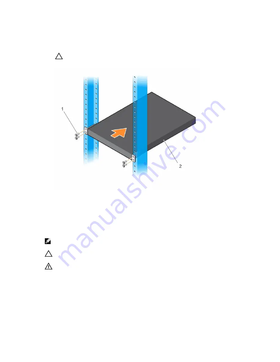
Secure the C1048P to the rack using the rack bolts (provided with the mount brackets) or cage nuts 
and cage-nut bolts with washers (provided with the rack). Tighten the bolts on the bottom of each 
bracket flange first; then tighten the bolts on top (item 1 in Figure 7). 

CAUTION: Make sure that the rack bolts provided with the mounting brackets fit the 
threaded holes in the rack.

Figure 7. Mounting the C1048P in a 2-Post Rack

Connecting to a C9010 Switch

The C1048P port extender has two 10G SFP+ ports on the front panel (see Figure 2). The two SFP+ ports 

provide 10GbE uplinks to a C9010 switch with SFP+ transceivers. At least one 10GbE SFP+ uplink is 

required to connect to a C9010 switch.

NOTE: A C1048P can connect to a C9010 switch only through a 10GbE SFP+ port; a C1048P 

cannot connect to a C9010 through a 10/100/1000 Mbps RJ-45 port.

CAUTION: ESD damage can occur if the components are mishandled. Always wear an ESD-

preventive wrist or heel ground strap when handling the PE and its components.

WARNING: When working with optical fibres, follow all the warning labels and always wear eye 
protection. Never look directly into the end of a terminated or unterminated fibre or connector 
as it may cause eye damage.

To connect to a C9010:

1.

Position the SFP+ optic correctly over a port. The optic has a key that prevents it from being inserted 
incorrectly.

2.

Insert the optic into an SFP+ port until it gently snaps into place.

Installing the Hardware

15

Summary of Contents for C1048P

Page 1: ...Dell Networking C1048P Getting Started Guide Regulatory Model C1048P ...

Page 2: ...problem WARNING A WARNING indicates a potential for property damage personal injury or death Copyright 2015 Dell Inc All rights reserved This product is protected by U S and international copyright and intellectual property laws Dell and the Dell logo are trademarks of Dell Inc in the United States and or other jurisdictions All other marks and names mentioned herein may be trademarks of their res...

Page 3: ...able which are available on the Dell Networking Support website Dell Networking Support Table 1 C1048P Documents Information Documentation Hardware installation and power up instructions Dell Networking C1048P Installation Guide Software configuration Dell Networking Configuration Guide for C9000 Series Switches Command line interface Dell Networking Command Line Reference Guide for C9000 Series S...

Page 4: ... supports PE stacking The C1048P PE has the following physical dimensions 440 0 x 257 0 x 43 5 mm W x D x H 17 3 x 15 2 x 1 7 inches W x D x H Unpacking the Switch The C1048P PE and its accessories ship in a single box Before unpacking the switch inspect the container and immediately report any evidence of damage Verify that you have received your ordered items If any item is missing or damaged co...

Page 5: ...8 data bits No Parity 1 Stop Bit and No Flow Control 2 USB port The Type A female USB port supports a USB 2 0 compliant flash memory drive The C1048P can read or write to a flash drive formatted as FAT 32 Use a USB flash drive to copy files and images to the C1048P 3 Reset button Access the reset button through a pinhole To perform a hard reset of the C1048P insert the tip of a paper clip or simil...

Page 6: ... PoE 15 4W and PoE 30W NOTE C1048P RJ 45 ports do not support half duplex mode By default all C1048P Gigabit Ethernet interfaces run in Layer 2 mode You can configure up to eight C1048P Gigabit Ethernet interfaces in a port channel that connects to a downstream edge device LED Descriptions Front Panel The light emitting diode LED displays for PE ID and stack number temperature power system stack m...
Page 7: ...ected to a C9010 a scrolling port extender ID PE ID from 0 to 255 displays in the left seven segment LED A fixed stack unit ID number from 0 to 7 displays in the right LED If the C1048P is not connected to a C9010 the PE ID LED is blank For more information see Pre provisioning a Port Extender NOTE The PE ID number displays as a scrolling three digit number Each digit displays briefly followed by ...

Page 8: ...Solid green The PE is receiving power Solid red An external power supply is detected but is not receiving power Stack Master Member Stack master status Off The PE is operating as a stack member Solid green The PE is operating as a stack master or in standalone mode NOTE While the C1048P is booting up in standalone or stacking mode the Stack Master LED is solid green SFP LNK left LED above port SFP...

Page 9: ... Member LED on the front panel indicates operational status standalone stack master or member unit For more information about C1048P LED behavior see System LEDs 2 Stack port 1 Activity LED 3 Stack port 1 Link LED 4 Main AC power supply connector The C1048P PE has an internal 1000 watt power supply that feeds up to 24 PoE devices at full PoE power 850W PoE power is dynamically allocated NOTE The A...

Page 10: ...g data Before You Start Site Preparation Before installing the C1048P port extender make sure that your installation site meets these requirements Clearance There is adequate space in front of the PE so you can read the LEDs and adequate space around and behind the switch for cabling power connections and ventilation The AC power cord can reach from the power outlet to the utility panel connector ...

Page 11: ...idity The relative humidity around the operating PE is 8 to 85 non condensing with a maximum humidity gradation of 10 per hour Dust Install the PE in an environment as free as possible from dust and foreign conductive material such as metal flakes from construction activities Cooling mechanisms such as fans and blowers in the switch can draw dust and other particles causing contaminant buildup ins...

Page 12: ...C1048P on a flat surface Make sure that it has proper ventilation by leaving 5 cm 2 inches on each side and 13 cm 5 inches at the back Before You Start Rack Safety Considerations Before installing the C1048P in a rack review the following rack mounting safety considerations WARNING For complete safety information read the safety instructions in your Safety Environmental and Regulatory Information ...

Page 13: ...tender with the rear panel facing in the downward position Installing a Rack Mount Tray Optional You can use a rack mount tray to support the weight of the C1048P in a 4 post rack You must order the tray separately To install a rack mount tray in a 4 post rack follow the instructions provided with the tray kit Decide on the desired height to mount the switch in the rack Position the tray at that h...

Page 14: ...attached from the underside of the C1048P CAUTION If you plan to install multiple C1048P PEs in a rack mount the C1048s from the bottom up Make sure that the air flow through the ventilation holes on each C1048P is not obstructed 1 Align the holes on the right rack mount bracket with the holes on the right side facing you of the C1048P 2 Secure the bracket item 3 in Figure 6 to the chassis by tigh...

Page 15: ...t one 10GbE SFP uplink is required to connect to a C9010 switch NOTE A C1048P can connect to a C9010 switch only through a 10GbE SFP port a C1048P cannot connect to a C9010 through a 10 100 1000 Mbps RJ 45 port CAUTION ESD damage can occur if the components are mishandled Always wear an ESD preventive wrist or heel ground strap when handling the PE and its components WARNING When working with opti...

Page 16: ...aster unit NOTE Although individual C1048P stack members do not require a separate uplink to a parent C9010 Dell Networking recommends connecting more than one C1048P stack unit to the C9010 for redundancy A C1048P stack unit uses the stacking connection to the master PE for its C9010 uplink For more information see Connecting to a C9010 Switch Creating a C1048P Stack Create a C1048P stack by conn...

Page 17: ... C1048P Standby A C1048P stack supports a standby or backup unit that assumes the stack master role if the master unit in the stack fails The parent C9010 maintains a synchronized copy of the running configuration for the stack When the system detects a stack master failure the C9010 initializes the standby unit and enables all other stack units with the current configuration Although the standby ...

Page 18: ...xternal DC power supply use the Dell Networking MPS1000 Connect the DC power cable from the power supply to the DC receptacle on the back panel After you connect the C1048P to a power source the C1048P boots up After a successful boot up the temperature power system status and fan LEDs display solid green The fans adjust to an operational speed based on the current traffic load The SFP Link LED di...

Page 19: ...nds before you install the C1048P with a parent C9010 the pre configured software settings download to the C1048P as soon as you attach it to a C9010 port and power it up NOTE Although you can provision a C1048P after you install and power it on Dell Networking recommends pre configuring the software provisioning before you install it Then connect the C1048P to a pre configured cascaded C9010 port...

Page 20: ...o six comma separated ranges or port numbers for example cascade interface tengigabitethernet 0 1 2 8 10 12 15 5 Verify the provisioned configuration on a C1048P EXEC Privilege mode Dell show pe brief Dell show pe pe id Dell show interface port channel brief Example of Provisioning a Port Extender Dell conf feature extended bridge Dell conf pe provision 2 Dell conf pe 2 stack unit 0 type c1048p De...

Page 21: ...igabit Ethernet ports support full duplex mode 10 100 1000 Mbps speeds on standard Category 5 UTP cable and Power over Ethernet PoE 15 4W and PoE 30W After the initial C1048P software provisioning is performed you can configure L2 and other software features on the C1048P by entering CLI commands on the C9010 console C1048P interfaces are identified in the command syntax interface peGigE pe id pe ...

Page 22: ...1048P ports are not supported For detailed information see the Dell Networking Configuration Guide for C9000 Series Switches When the C1048P is online you can enter the connect pe pe id command on the C9010 console to remotely log in to the C1048P CLI To log in enter the user name peadmin and the password calvin After logging in you can enter show and stack renumbering commands on the C1048P To mo...

Page 23: ...nformation in your language scroll down to the bottom of the web page and select your country from the drop down menu To obtain product specific information enter the 7 character service tag or 11 digit express service code of your C1048P and click Submit To view the service tag or express service code on a C1048P pull out the tag item 1 in Figure 10 on the upper left side of the back panel To rec...

Page 24: ...Figure 10 C1048P Service Tag 24 Dell Networking Support ...

Page 25: ...Storage temperature 40 F to 149 F 40 C to 65 C Storage relative humidity 85 non condensing Table 5 AC Power Requirements Parameter Specifications Nominal input voltage 100 240 VAC 50 60 Hz Maximum AC power supply input current based on 1200W output for 100 120V lines and 1600W output for 200 240V lines 8 9 A 100V per AC power supply 7 9 A 120V per AC power supply 3 85 A 200V per AC power supply 3 ...

Page 26: ...Parameter Specifications Maximum thermal output 1 017 BTU hr 110V 1 738W 1 440W PoE 298W switch power 26 Technical Specifications ...

Reviews: