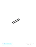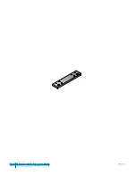
DSS 9000 rack manager module
Figure 33. DSS 9000 rack manager module
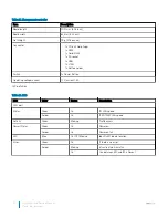
Table 25. DSS 9000 rack manager module features
Item
Description
Board length
323.25 mm (12.73 inch)
Board width
242.3 mm (9.54 inch)
Net Weight
1,050 g (37.03 ounce)
Connector
•
2 x 8-port RJ45
•
1 x 2-port RJ45
•
1 x (2x2) Power connector
•
1 x USB
•
1 x (1x5) connector
•
1 x Micro USB
Switch
1 x Reset Button
Operating voltage/current
12 V, current 2 A
Infrastructure module LED definition
Installation and Service Manual
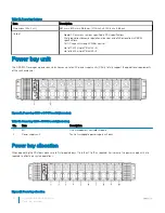
Power bay overview
55
Summary of Contents for B11S Series
Page 1: ...Dell EMC DSS 9000R Regulatory Model B11S Series Series Regulatory Type B11S001 ...
Page 9: ...Figure 2 Full width server blank Installation and Service Manual Rack accessories overview 9 ...
Page 11: ...Figure 3 Half width server blank Installation and Service Manual Rack accessories overview 11 ...
Page 17: ...Figure 8 Shipping bracket Installation and Service Manual Rack accessories overview 17 ...
Page 18: ...PDU brackets 18 Installation and Service Manual Rack accessories overview ...
Page 19: ...Figure 9 PDU bracket Installation and Service Manual Rack accessories overview 19 ...
Page 22: ...Figure 12 1GU bus bar protector 22 Installation and Service Manual Rack accessories overview ...
Page 24: ...Figure 14 2GU rack blank fillers 24 Installation and Service Manual Rack accessories overview ...
Page 25: ...Figure 15 3GU rack blank fillers Installation and Service Manual Rack accessories overview 25 ...
Page 26: ...Figure 16 5GU rack blank fillers 26 Installation and Service Manual Rack accessories overview ...
Page 30: ...Rear cabinet overview 3 30 Installation and Service Manual Rear cabinet overview ...
Page 40: ...Fan modules 40 Installation and Service Manual Rear cabinet overview ...
Page 41: ...Power bay overview 4 Installation and Service Manual Power bay overview 41 ...
Page 46: ...Rear view 46 Installation and Service Manual Power bay overview ...
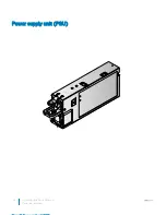
Page 48: ...Power supply unit PSU 48 Installation and Service Manual Power bay overview ...
Page 51: ...Management controller MC module Installation and Service Manual Power bay overview 51 ...
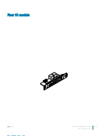
Page 53: ...Rear IO module Installation and Service Manual Power bay overview 53 ...
Page 59: ...Figure 37 Bus bar middle P positive red Installation and Service Manual Bus bar overview 59 ...
Page 60: ...Figure 38 Bus bar middle N negative black 60 Installation and Service Manual Bus bar overview ...
Page 63: ...Half width full width cross bus bar block Installation and Service Manual Bus bar overview 63 ...
Page 68: ...Bus bar PB 68 Installation and Service Manual Bus bar overview ...
Page 95: ...Fan modules Installation and Service Manual Installing and removing system components 95 ...


