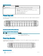
Table 13. Power bay features
No.
Item
Description
1
Top cover
Top cover for the power bay chassis.
2
Bus Bar PB
Bar strip to conduct electricity within the power bay.
3
PBPM
Power bay power module regulates power control for the PSU.
4
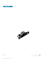
Rear IO module
Four RJ45 connectors, one 1x5 connector, one 1x6 connector and one 2x8
connector.
5
DSS 9000 rack manager module
Includes rack manager board (RMB) and infrastructure module (IM).
MC and blocks of the IM are networked through a LAN.
6
Power supply unit (PSU)
Ten hot-swappable power supply units.
7
Management controller module
Monitoring through the on-board GbE to provide real-time two-way fan
speed and power status and operational event information.
Topics:
•
Power bay specifications
•
Power bay unit
42
Installation and Service Manual
Power bay overview
Summary of Contents for B11S Series
Page 1: ...Dell EMC DSS 9000R Regulatory Model B11S Series Series Regulatory Type B11S001 ...
Page 9: ...Figure 2 Full width server blank Installation and Service Manual Rack accessories overview 9 ...
Page 11: ...Figure 3 Half width server blank Installation and Service Manual Rack accessories overview 11 ...
Page 17: ...Figure 8 Shipping bracket Installation and Service Manual Rack accessories overview 17 ...
Page 18: ...PDU brackets 18 Installation and Service Manual Rack accessories overview ...
Page 19: ...Figure 9 PDU bracket Installation and Service Manual Rack accessories overview 19 ...
Page 22: ...Figure 12 1GU bus bar protector 22 Installation and Service Manual Rack accessories overview ...
Page 24: ...Figure 14 2GU rack blank fillers 24 Installation and Service Manual Rack accessories overview ...
Page 25: ...Figure 15 3GU rack blank fillers Installation and Service Manual Rack accessories overview 25 ...
Page 26: ...Figure 16 5GU rack blank fillers 26 Installation and Service Manual Rack accessories overview ...
Page 30: ...Rear cabinet overview 3 30 Installation and Service Manual Rear cabinet overview ...
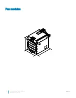
Page 40: ...Fan modules 40 Installation and Service Manual Rear cabinet overview ...
Page 41: ...Power bay overview 4 Installation and Service Manual Power bay overview 41 ...
Page 46: ...Rear view 46 Installation and Service Manual Power bay overview ...
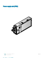
Page 48: ...Power supply unit PSU 48 Installation and Service Manual Power bay overview ...
Page 51: ...Management controller MC module Installation and Service Manual Power bay overview 51 ...
Page 53: ...Rear IO module Installation and Service Manual Power bay overview 53 ...
Page 59: ...Figure 37 Bus bar middle P positive red Installation and Service Manual Bus bar overview 59 ...
Page 60: ...Figure 38 Bus bar middle N negative black 60 Installation and Service Manual Bus bar overview ...
Page 63: ...Half width full width cross bus bar block Installation and Service Manual Bus bar overview 63 ...
Page 68: ...Bus bar PB 68 Installation and Service Manual Bus bar overview ...
Page 95: ...Fan modules Installation and Service Manual Installing and removing system components 95 ...


