Back to Contents Page
Processor Thermal-Cooling Assembly
Dell™ Studio 1535/1536 Service Manual
Removing the Processor Thermal-Cooling Assembly
1.
Follow the instructions in
Before You Begin
.
2.
Turn the computer over and remove the base cover (see
Removing the Base Cover
).
3.
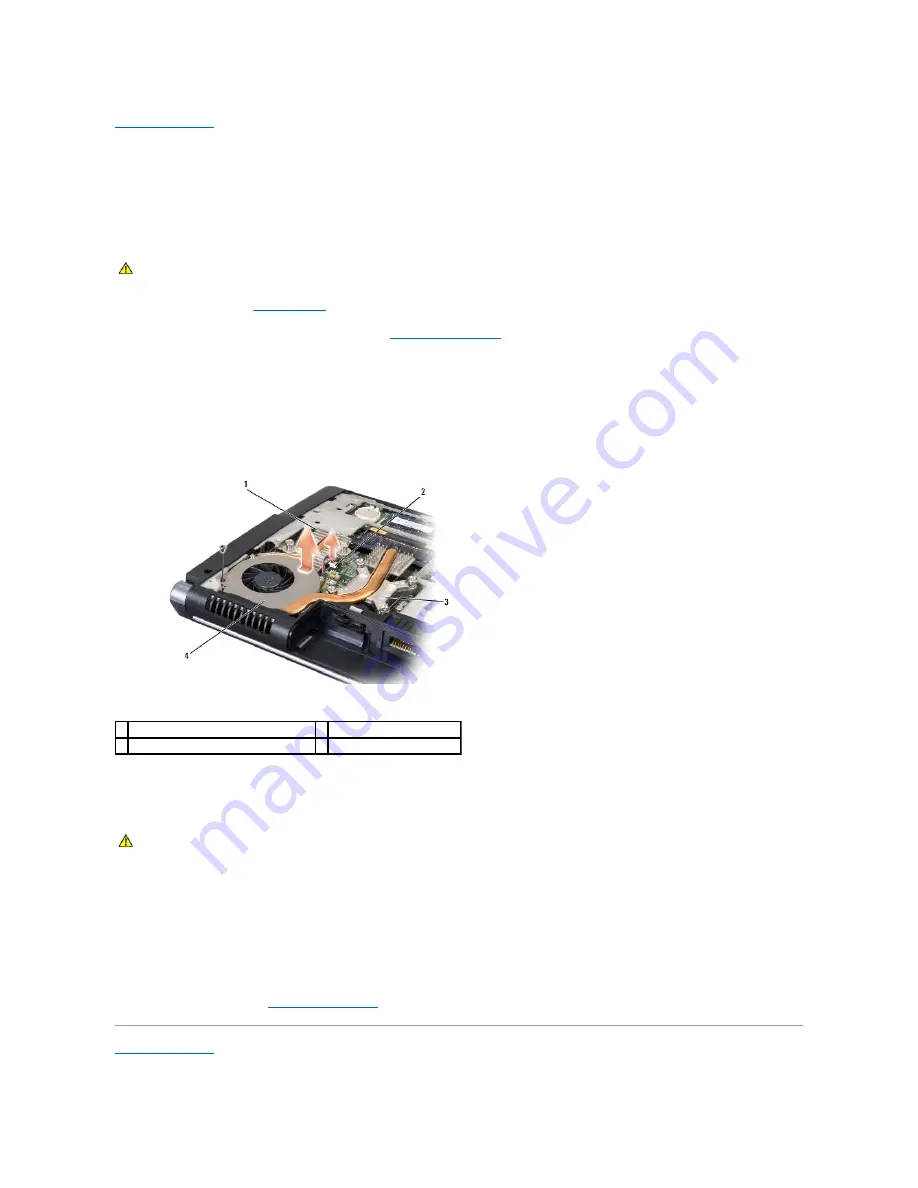
In sequential order (indicated on the thermal-cooling assembly), loosen the four captive screws on the thermal-cooling assembly processor cover.
4.
Loosen the two captive screws on the thermal-cooling assembly sink.
5.
Disconnect the thermal-cooling assembly fan cable from the connector on the system board.
6.
Remove the screw from the thermal-cooling assembly fan and take out the thermal-cooling assembly.
Replacing the Processor Thermal-Cooling Assembly
1.
Align the four captive screws on the processor thermal-cooling assembly processor cover with the screw holes on the system board and tighten the
screws in sequential order.
2.
Tighten the two captive screws securing the thermal-cooling assembly sink to the system board.
3.
Replace and tighten the screw to secure the thermal-cooling assembly fan to the system board.
4.
Connect the thermal-cooling assembly fan cable to the system board.
5.
Replace the base cover (see
Replacing the Base Cover
).
Back to Contents Page
CAUTION:
Before you begin the following procedure, follow the safety instructions that shipped with your computer.
1 thermal-cooling assembly sink
2 fan cable
3 thermal-cooling assembly processor cover 4 thermal-cooling assembly fan
CAUTION:
Before you begin the following procedure, follow the safety instructions that shipped with your computer.
Summary of Contents for 1537 - Studio Core 2 Duo T6400 2.0GHz 4GB 320GB
Page 15: ......
Page 34: ...Back to Contents Page ...
Page 36: ...Back to Contents Page 1 optical drive 2 optical drive interposer ...


