Dell EMC Unity All Flash Field Upgrade Procedure Download Page 28

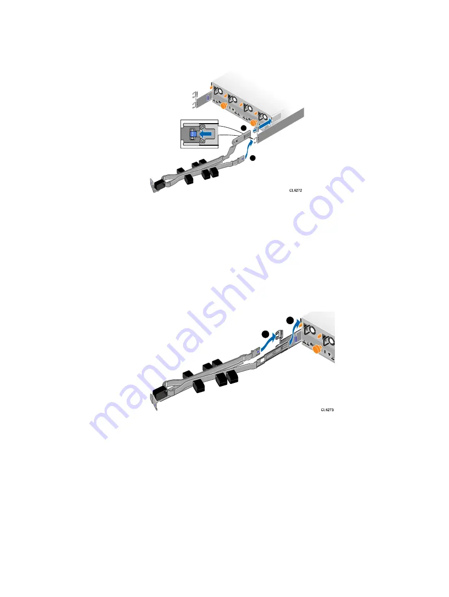
Figure 25 Installing an A-side cable management arm

2

1

2. Install the B-side cable management arm:

a. On the B-side, align the long straight retention latch end of the arm with the

enclosure bracket, and carefully insert it into the enclosure bracket until you
feel and hear an audible click.

b. Swing the extension arm into alignment with the upper rail bracket.

c. Press the short retention latch onto the upper rail bracket.

d. Make sure that you hear the audible click that indicates that the cable

management arm is in place.

Figure 26 Installing a B-side cable management arm

2

1

Closing the cable management arms

Perform this procedure to close the cable management arms.

Procedure

1. Close the A-side cable management arm:

a. Swing the A-side cable management arm to the left side of the enclosure,

and align the short retention latch with the lower rail bracket.

b. Press the short retention latch onto the lower rail bracket.

c. Make sure that you hear the audible click that indicates that the A-side cable

management arm is in place.

2. Close the B-side cable management arm:

Field Upgrade Procedure

28

Unity All Flash and Unity Hybrid


Field Upgrade Procedure

Summary of Contents for Unity All Flash

Page 1: ...ry and or damage to the equipment do not attempt to lift and install the enclosure into a rack without a mechanical lift and or help from another person Note You do not have to power off any components to add a 80 drive DAE If an additional 12 Gb SAS back end I O module is required to complete the installation persisting that I O module requires a coordinated reboot of the array NOTICE When Data a...

Page 2: ...Technical Documentation at www emc com en us documentation unity family htm Troubleshooting For information about products software updates licensing and service go to Online Support registration required at https Support EMC com After logging in locate the appropriate Support by Product page Technical support For technical support and service requests go to Online Support at https Support EMC com...

Page 3: ...tatic packaging until you are ready to install them l Before you begin service gather together the ESD kit and all other materials you will need l Once servicing begins avoid moving away from the work site otherwise you may build up an electrostatic charge l Use ESD anti static gloves or an ESD wristband with strap If using an ESD wristband with a strap n Attach the clip of the ESD wristband to th...

Page 4: ...ng power This requires the unpackaged system or component to reside in the operating environment for up to 16 hours in order to thermally stabilize and prevent condensation Refer to the table Table 1 on page 4 to determine the precise amount of stabilization time required Table 1 Hardware acclimation times systems and components If the last 24 hours of the TRANSIT STORAGE environment was this and ...

Page 5: ...r connectors on the module for any damage before attempting its installation l A sudden jar drop or even a moderate vibration can permanently damage some sensitive replaceable units l Do not remove a faulted replaceable unit until you have the replacement available l When handling replaceable units avoid electrostatic discharge ESD by wearing ESD anti static gloves or an ESD wristband with a strap...

Page 6: ...g material to return the faulted part Standard touch point colors Touch points are component locations where you can l Grip the hardware to remove or install a component l Open or close a latch l Turn a knob to open close or adjust a component Standard touch point colors are terra cotta orange or blue Note Within this documentation the color orange is used instead of terra cotta for simplicity Tab...

Page 7: ... approved replacement for the faulted disk The part number PN005xxxxxx appears on the disk A replacement disk should be the same type example SAS FLASH and have the same capacity size and speed as the disk it is replacing l When removing a spinning disk pull the disk partially out of the slot then wait 30 seconds for the drive to spin down before removing it l When installing multiple disks in a p...

Page 8: ...x8 cabling However special steps must be taken before powering on the system If you are connecting the DAE to a 4 port SAS SLIC that requires x8 connectivity insert the SAS cable into the 4 port SAS SLIC before persisting the SLIC The 4 port SAS SLIC must be persisted with the cable inserted for x8 connectivity Note If the SAS back end SLIC is powered on without any cables inserted it is automatic...

Page 9: ...needed to install the new 80 drive DAE Verify that you received the following Table 3 80 drive DAE kit Component Quantity Disk array enclosure DAE 1 SAS cables either 1 meter or 2 meter copper that connect disk array enclosures to each other 1 meter cables or to DPE 2 meter cables 2 Table 4 Rail kit Component Quantity Rails each stamped L and R 2 Power cords AC 4 2 gray cables and 2 black cables B...

Page 10: ...handle downward to unlock it and outward to separate it from the chassis b Repeat these steps for the remaining handles Working with the portable lift If the DAE with all of the FRUs removed is being installed the chassis can be installed without using the lift If the DAE is populated with FRUs prior to installing then this task requires the use of a portable lift The portable lift commonly used b...

Page 11: ...ove the floor l For installations at or below 49 inches you must use the lower mast configuration l For installations above 49 inches use the Voyager conversion kit rated for 225 pounds and a support table with the lower mast configuration Planning your lift You can use the lift positioned along the side of the DAE or directly in the front of it If possible position the lift adjacent to the LONG s...

Page 12: ...scription For installations at or below 49 inches 28U above floor level You must use the lower single mast configuration Refer to Using the lift on an enclosure less than 49 above the floor For installations 49 inches 28U above floor level Use the Voyager conversion kit and a support table kit with the lower single mast configuration See Using the lift on an enclosure more than 49 above the floor ...

Page 13: ...n the kit to reconfigure the lift Figure 4 Reconfiguring the portable lift with the Voyager conversion kit CL5422 1 2 Adjusting the arms for a frontal lift If you plan to use the mechanical lift directly in front of the cabinet adjust the lift arm tray width to just under 17 inches apart to ensure that the arms will stay under the chassis Figure 5 on page 14 shows an example of adjusting the lift ...

Page 14: ...from its mounting hole b Hold the arm with one hand while pressing the plunger on the top ball lock pin and pulling the pin out with the other hand It may be necessary to wiggle the pin with the plunger pressed to free it from its mounting hole The arm will be free of the lift chassis c Remove the arm from the lift and reverse it to achieve the desired orientation The adaptor will be attached to t...

Page 15: ...f the portable lift to the approximate height of the enclosure you intend to move 5 Attach the tray to the lift arm 6 Lock all four casters by pressing down on the locking tab so the lift will not roll as the instrument is placed onto it Refer to Locking the Casters Figure 7 Locking the Casters CL5423 7 Pull the enclosure onto the lift Refer to Removing an enclosure from rails 49 or less above the...

Page 16: ...et handle down to tighten the securing strap around the lift and the enclosure Refer to Tightening the Straps Figure 9 Tightening the Straps 1 2 CL5429 c Make sure the enclosure is securely strapped to the lift before moving Lower the lift to its lowest point of travel This allows the enclosure to be moved with minimal danger of tipping over Field Upgrade Procedure 16 Unity All Flash and Unity Hyb...

Page 17: ...1 Removing the Straps 1 CL5430 2 Using the lift on an Enclosure more than 49 above the floor If you are using an Alum A Lift to work on a enclosure that is more than 49 inches above the floor you must use the Voyager conversion kit and a support table with the lower mast configuration Refer to Adjusting the arm for a high rail position while performing this task Procedure 1 If necessary orient the...

Page 18: ...of the lift chassis c Remove the arm from the lift and reverse it to achieve the desired orientation d Attach the arm to the lift chassis by aligning the mounting holes pressing the plunger and inserting the ball lock pins into the holes Insert the top pin first 2 Remove the rotating handle if necessary by loosening the set screw and pulling the handle from the hex fitting 3 Install and configure ...

Page 19: ...equired height With the enclosure extended from the rack on the rails pull the enclosure from the rails and onto the lift Secure the enclosure to the portable lift using the securing straps as follows Figure 14 Removing an enclosure from rails more than 49 above the floor CL5431 a Place the securing strap around the lift and the enclosure Adding an optional 80 drive DAE Working with the portable l...

Page 20: ...supported by the arm lower the arm to the lowest point that still permits travel This allows the enclosure to be moved with minimal danger of tipping over 6 Unlock the casters by lifting up on the locking tabs and move the enclosure as required Refer to Unlocking the casters Figure 16 Unlocking the Casters CL5424 7 Move the enclosure to the support table Use the drill to raise or lower the enclosu...

Page 21: ...Removing the Straps Figure 18 Removing the Straps 1 CL5430 2 9 To move the enclosure to the deck or to a shipping pallet the lift arm must be in the lower mast position Refer to Using the Portable Lift Below 49 inches Opening the door or console Open the door or console if one is present Adding an optional 80 drive DAE Opening the door or console 21 ...

Page 22: ...ils Install the rails from the front of the cabinet into which you are installing the enclosure The 3U DAE enclosure includes inner rails that slide into the cabinet rail assembly The rails are dedicated left and right and cannot be interchanged The front side of each rail is labeled L or R for left or right side when the rail faces the cabinet front Note When installing rails into a Dell EMC cabi...

Page 23: ...e front of the right rail so that it is level and the front rail pins are aligned with the middle holes of the bottom two U spaces of the 3U space b Pull the rail forward with the posts aligned with the middle NEMA holes of the bottom two U spaces of the 3U space An audible click indicates that the connection is secure 4 Install the left rail L by mirroring step 2 and step 3 5 On both left and rig...

Page 24: ...s rated for 400 pounds and is for raising or lowering objects 28U 49 inches or less above the floor The dual mast configuration is rated well under 200 pounds and is for raising objects more than 28U 49 inches above the floor l For installations at or below 49 inches you must use the lower mast configuration l For installations above 49 inches use the Voyager conversion kit rated for 225 pounds an...

Page 25: ...sagging tension on the chassis by pulling the lift arms tray up slightly 4 Release the lift casters and carefully slide the chassis into the cabinet as far as the lift will allow 5 Secure the lift casters on the floor 6 Carefully push the chassis off the lift arms tray and into the cabinet CAUTION Make sure to leave the lift under the chassis until the enclosure is safely balanced and secured with...

Page 26: ...e Figure 23 Inserting the chassis into the cabinet and securing with captive screws CL5383 2 1 3 Insert chassis securing screws These screws prevent removal of the DAE using the orange release handles They also secure the DAE chassis to the cabinet rails in the event the cabinet needs to be moved Ensure that these securing screws have been installed or re installed after servicing the cabinet a Us...

Page 27: ...ffset enclosure retention latch The enclosure retention latch on the B side cable management arm is straight Procedure 1 Install the A side cable management arm a On the A side align the long offset retention latch end of the arm with the enclosure bracket and carefully insert it into the enclosure bracket until you feel and hear an audible click Both rails have two attachment brackets for the cab...

Page 28: ...ates that the cable management arm is in place Figure 26 Installing a B side cable management arm 2 1 Closing the cable management arms Perform this procedure to close the cable management arms Procedure 1 Close the A side cable management arm a Swing the A side cable management arm to the left side of the enclosure and align the short retention latch with the lower rail bracket b Press the short ...

Page 29: ...the B side cable management arm is in place Figure 27 Closing the cable management arms 2 1 Securing cables to the cable management arms Perform this procedure to secure the cables to the cable management arms Procedure 1 Lift the latches on each cable holder on the cable management arm 2 Insert the cables in the cable holders along the arm 3 Snap shut the latches on the cable holders Adding an op...

Page 30: ...appropriate cables as you connect the cables Note If your system was assembled at the factory all the cable labels have been affixed to the cables except for any DAEs you have ordered Additionally if your system was not assembled at the factory the cable kit supplied with your product will have all the required cables already labeled except for the DAEs Attaching expansion back end cables to an 80...

Page 31: ...f even distribution of drives over all of the back end busses This section provides three different ways to connect the DAE to the array with an x4 connection l Connecting to back end bus 1 l Connecting to back end bus 0 l Connecting to a port on the SAS I O module Each installation may be different Choose the connection option that suits your needs Procedure l Connect to back end bus 1 To connect...

Page 32: ... to the address of this enclosure as BE0 EA1 0_1 a Label a pair of mini SAS HD cables using the orange labels shown here Back end bus and enclosure number Cable label Expansion port cable labeling details Primary port cable labeling details Label part number Label Port Label part number Label Port BE0 Enclosure 1 A side 046 001 561 SP A SAS 0 SP A SAS 0 SP A SAS 0 SP A SAS 0 046 001 561_xx SP A SA...

Page 33: ...ort Label part number Label Port BE2 enclosure 0 and above A side 046 005 679 SP A A0 PORT 0 046 005 679_xx SP A A0 PORT 0 SP A A0 PORT 0 SP A A0 PORT 0 SP A A0 PORT 0 046 021 16 LCC A Port A 046 021 016_xx LCC A Port A LCC A Port A LCC A Port A LCC A Port A BE2 enclosure 0 and above B side 046 005 718 SP B B0 PORT 0 046 005 718_xx SP B B0 PORT 0 SP B B0 PORT 0 SP B B0 PORT 0 SP B B0 PORT 0 046 02...

Page 34: ... SP A A0 PORT 3 046 005 679_xx SP A A0 PORT 3 SP A A0 PORT 3 SP A A0 PORT 3 SP A A0 PORT 3 046 021 022 LCC A Port A 046 021 022_xx LCC A Port A LCC A Port A LCC A Port A LCC A Port A BE5 enclosure 0 and above B side 046 005 938 SP B B0 PORT 3 046 005 718_xx SP B B0 PORT 3 SP B B0 PORT 3 SP B B0 PORT 3 SP B B0 PORT 3 046 021 023 LCC B Port A 046 021 023_xx LCC B Port A LCC B Port A LCC B Port A LCC...

Page 35: ...he SAS cable into the 4 port SAS I O module before persisting it The 4 port SAS I O module must be persisted with the cable inserted for x8 connectivity If the SAS back end I O module is powered on and persisted without any cables inserted it is automatically set at x4 and cannot be used for x8 lane cabling Adding an optional 80 drive DAE Attaching expansion back end cables to an 80 drive DAE 35 ...

Page 36: ... using the black or green labels The labels used depend upon how the back end ports are configured b Connect the ports as follows n Ensure that the SAS cable is inserted into ports 0 and 1 or ports 2 and 3 of the SP A SAS module located in the bottom storage processor of the DPE Connect the cable to ports AA A of link control card A LCC A located on the right side of the DAE n Ensure that the SAS ...

Page 37: ...Connect power supplies B0 and B1 the two left most power supplies to the same power bar using the two black power supply cables b Connect power supplies A0 and A1 the two right most power supplies to the same power bar using the two gray power supply cables 2 Plug the power cable into the connector on the power supply Adding an optional 80 drive DAE Attaching DAE power cable to each power supply 3...

Page 38: ...cables and back end cables using the lower A side CMA 2 For SP B route DAE power cables and back end cables using the upper B side CMA After you finish Fully open and close the DAE to test the cable management arms and cable routing to ensure that proper slack has been provided for the cables Loosen any tight cables so that removing or inserting the DAE does not pull out a cable from its port Inst...

Page 39: ...losed Verifying the new 80 drive DAE Verify that the new 80 drive DAE is recognized by your system and operating correctly using the procedure that follows Procedure 1 In Unisphere select System View 2 On the Summary page confirm that the system status is OK 3 Select the Enclosures page 4 Verify that the 80 drive DAE appears with OK status in the enclosure view You may need to refresh Unisphere by...

Page 40: ...ANY KIND WITH RESPECT TO THE INFORMATION IN THIS PUBLICATION AND SPECIFICALLY DISCLAIMS IMPLIED WARRANTIES OF MERCHANTABILITY OR FITNESS FOR A PARTICULAR PURPOSE USE COPYING AND DISTRIBUTION OF ANY DELL SOFTWARE DESCRIBED IN THIS PUBLICATION REQUIRES AN APPLICABLE SOFTWARE LICENSE Dell EMC and other trademarks are trademarks of Dell Inc or its subsidiaries Other trademarks may be the property of t...

Reviews: