background image

Installing the processor into a processor and heat sink module

Prerequisites

1

Follow the safety guidelines listed in 

Safety instructions

.

2

Follow the procedure listed in 

Before working inside your system

.

3

Remove the processor and heat sink module

.

Steps

Place the processor in the processor tray.

NOTE: 

Ensure that the pin 1 indicator on the processor tray is aligned with the pin 1 indicator on the processor.
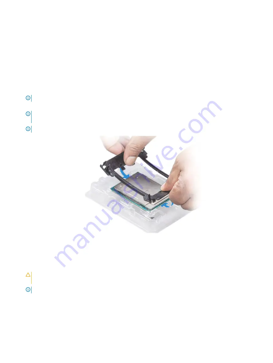
Flex the outer edges of the bracket around the processor ensuring that the processor is locked into the clips on the bracket.

NOTE: 

Ensure that the pin 1 indicator on the bracket is aligned with the pin 1 indicator on the processor before placing the 

bracket on the processor.

NOTE: 

Ensure that the processor and the bracket are placed in the tray before you install the heat sink.

Figure 64. Installing the processor bracket

If you are using an existing heat sink, remove the thermal grease from the heat sink by using a clean lint-free cloth.

Use the thermal grease syringe included with your processor kit to apply the grease in a quadrilateral design on the top of the 
processor.

CAUTION: 

Applying too much thermal grease can result in excess grease coming in contact with and contaminating the 

processor socket.

NOTE: 

The thermal grease syringe is intended for single use only. Dispose the syringe after you use it.

98

Installing and removing system components

Summary of Contents for PowerEdge R840

Page 1: ...Dell EMC PowerEdge R840 Installation and Service Manual Regulatory Model E49S Series Regulatory Type E49S001 ...

Page 2: ...amage to hardware or loss of data and tells you how to avoid the problem WARNING A WARNING indicates a potential for property damage personal injury or death 2018 Dell Inc or its subsidiaries All rights reserved Dell EMC and other trademarks are trademarks of Dell Inc or its subsidiaries Other trademarks may be trademarks of their respective owners 2018 05 Rev A00 ...

Page 3: ...9 Downloading drivers and firmware 20 4 Pre operating system management applications 21 Options to manage the pre operating system applications 21 System Setup 21 System Setup details 21 System BIOS 22 iDRAC Settings utility 38 Device Settings 39 Dell Lifecycle Controller 39 Embedded System Management 39 Boot Manager 39 Viewing Boot Manager 39 Boot Manager main menu 39 One shot UEFI Boot menu 40 S...

Page 4: ...emoving the drive from the drive carrier 62 Installing a drive into the drive carrier 62 Rear drive cage 63 Removing the rear drive cage 63 Installing the rear drive cage 64 System memory 65 System memory population guidelines 65 General memory module installation guidelines 67 NVDIMM N memory module installation guidelines 67 Mode specific guidelines 70 Removing a memory module 73 Installing a me...

Page 5: ...rive backplane 109 Drive mapping 111 Removing drive backplane 111 Installing drive backplane 112 Cable routing 114 System battery 119 Replacing system battery 119 Optional USB 3 0 module 120 Removing USB 3 0 module 120 Installing USB 3 0 module 121 Optional internal USB memory key 122 Replacing optional internal USB memory key 122 Optional optical drive 123 Removing optical drive 123 Installing op...

Page 6: ...ssis weight 149 Processor specifications 150 PSU specifications 150 System battery specifications 151 Expansion card riser specifications 151 Memory specifications 151 RAID controller specifications 152 Drive specifications 152 Hard drives 152 Optical drives 152 Tape drives 153 Ports and connectors specifications 153 USB ports 153 NIC ports 153 VGA ports 154 Serial connector 154 IDSDM or vFlash mo...

Page 7: ...8 Using system diagnostics 169 Dell Embedded System Diagnostics 169 9 Getting help 170 Contacting Dell 170 Documentation feedback 170 Accessing system information by using QRL 170 Receiving automated support with SupportAssist 171 Quick Resource Locator for PowerEdge R840 system 171 10 Documentation resources 172 Contents 7 ...

Page 8: ...ument provides an overview about the system information about installing and replacing components technical specifications diagnostic tools and guidelines to be followed while installing certain components 1 8 About this document ...

Page 9: ...es For more information about supported drives see the Technical specifications section NOTE All instances of SAS SATA hard drives NVMe and SSDs are referred to as drives in this document unless specified otherwise Topics Front view of the system Back view of the system Inside the system Locating the Service Tag of your system Front view of the system Figure 1 Front view 24 x 2 5 inch drive system...

Page 10: ...the server Left control panel Figure 3 Left control panel view with optional iDRAC Quick Sync 2 0 indicator 1 Status LED indicators 2 System health and system ID indicator 3 iDRAC Quick Sync 2 wireless indicator optional NOTE iDRAC Quick Sync 2 feature allows you to manage your system using mobile devices This feature is only available on certain configurations For more information about the featu...

Page 11: ...ont bezel The optional front bezel is hot pluggable The statuses and conditions of the LCD panel are outlined here The LCD backlight is white during normal operating conditions When the system needs attention the LCD backlight turns amber and displays an error code followed by descriptive text NOTE If the system is connected to a power source and an error is detected the LCD turns amber regardless...

Page 12: ...y mode after five minutes of inactivity Press any button on the LCD to turn it on 1 To view the Home screen press one of the three navigation buttons Select Left or Right 2 To navigate to the Home screen from another menu complete the following steps a Press and hold the navigation button till the up arrow is displayed b Navigate to the Home icon using the up arrow c Select the Home icon d On the ...

Page 13: ...DRAC iSCSI or Network devices Name Displays the name of the Host Model or User String for the system Number Displays the Asset tag or the Service tag for the system Power Displays the power output of the system in BTU hr or Watts The display format can be configured in the Set home submenu of the Setup menu Temperature Displays the temperature of the system in Celsius or Fahrenheit The display for...

Page 14: ...s 2 5 System identification button 6 iDRAC9 dedicated port 7 USB 3 0 ports 2 8 VGA port 9 Serial port 10 NIC ports 4 11 Rear handle NOTE For more information about the ports and connectors see the Technical Specifications section Inside the system NOTE Components that are hot swappable have orange touch points and the components that are not hot swappable have blue touch points 14 PowerEdge R840 s...

Page 15: ...tem without rear drive cage 1 Drive backplane 2 SAS Expander board 3 Cooling fans 6 4 System board 5 Full height expansion card Riser 2 6 Full height expansion card Riser 1 7 Intrusion switch PowerEdge R840 system overview 15 ...

Page 16: ...ag Pull out the information tag in front of the system to view the Express Service Code and Service Tag Alternatively the information may be on a sticker on the chassis of the system The mini Enterprise Service Tag EST is found on the back of the system This information is used by Dell to route support calls to the appropriate personnel Figure 10 Locating Service Tag of your system 1 Information t...

Page 17: ...s to iDRAC the iDRAC secure default password is available on the back of the system Information tag This section of label will be blank if you have not opted for secure default access to iDRAC then the default user name and password are root and calvin 5 Service Tag PowerEdge R840 system overview 17 ...

Page 18: ...ts administrators to system issues helps them perform remote system management and reduces the need for physical access to the system Options to set up iDRAC IP address You must configure the initial network settings based on your network infrastructure to enable the communication to and from iDRAC NOTE For static IP configuration you must request for it at the time of purchase You must use the de...

Page 19: ... IP address For more information about logging in to the iDRAC and iDRAC licenses see the latest Integrated Dell Remote Access Controller User s Guide at Dell com idracmanuals You can also access iDRAC by using RACADM For more information see the RACADM Command Line Interface Reference Guide at Dell com idracmanuals Options to install the operating system If the system is shipped without an operat...

Page 20: ... and install the latest BIOS drivers and systems management firmware on your system Prerequisite Ensure that you clear the web browser cache before downloading the drivers and firmware Steps 1 Go to Dell com support drivers 2 In the Drivers Downloads section type the Service Tag of your system in the Enter a Service Tag or product ID box and then click Submit NOTE If you do not have the Service Ta...

Page 21: ...ice settings of your system NOTE Help text for the selected field is displayed in the graphical browser by default To view the help text in the text browser press F1 You can access system setup by using two methods Standard graphical browser The browser is enabled by default Text browser The browser is enabled by using Console Redirection System Setup details The System Setup Main Menu screen deta...

Page 22: ...E If your operating system begins to load before you press F2 wait for the system to finish booting and then restart your system and try again 3 On the System Setup Main Menu screen click System BIOS 4 On the System BIOS screen click System Information System Information details The System Information screen details are explained as follows Option Description System Model Name Specifies the system...

Page 23: ...of memory installed in the system System Memory Speed Specifies the system memory speed System Memory Voltage Specifies the system memory voltage Video Memory Specifies the amount of video memory System Memory Testing Specifies whether the system memory tests are run during system boot Options are Enabled and Disabled This option is set to Disabled by default Memory Operating Mode Specifies the me...

Page 24: ...essor Settings screen details are explained as follows Option Description Logical Processor Enables or disables the logical processors and displays the number of logical processors If this option is set to Enabled the BIOS displays all the logical processors If this option is set to Disabled the BIOS displays only one logical processor per core This option is set to Enabled by default CPU Intercon...

Page 25: ...d parks some of the logical processors in the system which in turn allows the corresponding processor cores to transition into a lower power idle state This option can only be enabled if the operating system supports it It is set to Disabled by default NOTE This feature is not supported if CPU Power Management is set to Maximum Performance x2APIC Mode Enables or disables the x2APIC mode This optio...

Page 26: ...option is set to AHCI Mode by default Security Freeze Lock Sends Security Freeze Lock command to the embedded SATA drives during POST This option is set to Enabled by default Write Cache Enables or disables the command for the embedded SATA drives during POST This option is set to Disabled by default Port n Sets the drive type of the selected device For AHCI Mode or RAID Mode BIOS support is alway...

Page 27: ...s the legacy boot mode It is maintained for backward compatibility UEFI The Unified Extensible Firmware Interface UEFI is a new interface between operating systems and platform firmware The interface consists of data tables with platform related information also boot and runtime service calls that are available to the operating system and its loader The following benefits are available when the Bo...

Page 28: ...le Disable Enables you to enable or disable the PXE boot devices Network Settings You can use the Network Settings screen to modify UEFI PXE iSCSI and HTTP boot settings The network settings option is available only in the UEFI mode NOTE The BIOS does not control network settings in the BIOS mode For the BIOS boot mode the optional Boot ROM of the network controllers handles the network settings V...

Page 29: ... on or restart your system 2 Press F2 immediately after you see the following message F2 System Setup NOTE If your operating system begins to load before you press F2 wait for the system to finish booting and then restart your system and try again 3 On the System Setup Main Menu screen click System BIOS 4 On the System BIOS screen click Integrated Devices Integrated Devices details The Integrated ...

Page 30: ...matically used as the primary display even if the Embedded Video Controller setting is set to Enabled SR IOV Global Enable Enables or disables the BIOS configuration of Single Root I O Virtualization SR IOV devices This option is set to Disabled by default OS Watchdog Timer If your system stops responding this watchdog timer aids in the recovery of your operating system When this option is set to ...

Page 31: ...Bifurcation or Auto discovery of Bifurcation Table 6 Slot Bifurcation Option Description Auto Discovery Bifurcation Settings Platform Default Bifurcation Auto Bifurcation Manual bifurcation Slot 1 Bifurcation x4 Bifurcation or x8 Bifurcation Slot 2 Bifurcation x16 Bifurcation or x8 Bifurcation or x4 Bifurcation or x4 x4 x8 Bifurcation or x8 x4 x4 Bifurcation Slot 3 Bifurcation x16 Bifurcation or x...

Page 32: ...e Serial Over LAN SOL feature To use console redirection by SOL configure the same port address for console redirection and the serial device External Serial Connector Enables you to associate the External Serial Connector to Serial Device 1 Serial Device 2 or the Remote Access Device by using this option This option is set to Serial Device 1 by default NOTE Only Serial Device 2 can be used for Se...

Page 33: ... is set to Custom CPU Power Management Sets the CPU power management This option is set to System DBPM DAPC by default DBPM is Demand Based Power Management Memory Frequency Sets the speed of the system memory You can select Maximum Performance or a specific speed This option is set to Maximum Performance by default Turbo Boost Enables or disables the processor to operate in the turbo boost mode T...

Page 34: ...tion is set to Enabled by default System Security You can use the System Security screen to perform specific functions such as setting the system password setup password and disabling the power button Viewing System Security To view the System Security screen perform the following steps 1 Turn on or restart your system 2 Press F2 immediately after you see the following message F2 System Setup NOTE...

Page 35: ... information TPM Information Changes the operational state of the TPM This option is set to No Change by default TPM Firmware Indicates the firmware version of the TPM TPM Hierarcy Enable disable or clear the storage and endorsement hierarchies When set to Enabled the storage and endorsement hierarchies can be used When set to Disabled the storage and endorsement hierarchies cannot be used When se...

Page 36: ...he BIOS uses the system manufacturer s key and certificates to authenticate pre boot images When Secure Boot policy is set to Custom the BIOS uses the user defined key and certificates Secure Boot policy is set to Standard by default Secure Boot Mode Configures how the BIOS uses the Secure Boot Policy Objects PK KEK db dbx If the current mode is set to Deployed Mode the available options are User ...

Page 37: ...p disk from the following devices None Internal SD card SATA Ports in AHCI mode BOSS PCIe cards Internal M 2 Drives Internal USB NOTE RAID configurations and NVMe cards not are included as BIOS does not have the ability to distinguish between individual drives in those configurations Redundant OS State NOTE This option is disabled if Redundant OS Location is set to None When set to Visible the bac...

Page 38: ...n does not apply to 84 key keyboards F1 F2 Prompt on Error Enables or disables the F1 F2 prompt on error This option is set to Enabled by default The F1 F2 prompt also includes keyboard errors Load Legacy Video Option ROM Enables you to determine whether the system BIOS loads the legacy video INT 10H option ROM from the video controller Selecting Enabled in the operating system does not support UE...

Page 39: ...r configuring hardware and firmware and deploying the operating system see the Dell Lifecycle Controller documentation at Dell com idracmanuals Boot Manager The Boot Manager screen enables you to select boot options and diagnostic utilities Viewing Boot Manager About this task To enter Boot Manager Steps 1 Turn on or restart your system Enter the result of your step here optional 2 Press F11 when ...

Page 40: ...t menu and select an one shot boot option to boot from System Utilities System Utilities contains the following utilities that can be launched Launch Diagnostics BIOS Update File Explorer Reboot System PXE boot You can use the Preboot Execution Environment PXE option to boot and configure the networked systems remotely To access the PXE boot option boot the system and then press F12 during POST in...

Page 41: ...d that you always use an antistatic mat and antistatic strap while working on components inside the system CAUTION To ensure proper operation and cooling all bays in the system and system fans must be always populated with a component or a blank Before working inside your system Prerequisite Follow the safety guidelines listed in Safety instructions Steps 1 Turn off the system including all attach...

Page 42: ...ire stripper pliers to remove insulation from size 10 AWG solid or stranded insulated copper wire NOTE Use alpha wire part number 3080 or equivalent 65 30 stranding Optional front bezel A lock on the bezel is used to protect unauthorized access to the drives The system status can be viewed on the bezel with the LCD panel For more information see the LCD panel section Removing front bezel Prerequis...

Page 43: ...s listed in Safety instructions 2 Locate and remove the bezel key NOTE The bezel key is part of the LCD bezel package Steps 1 Align and insert the right end of the bezel onto the system 2 Press the release button and fit the left end of the bezel onto the system 3 Lock the bezel by using the key Installing and removing system components 43 ...

Page 44: ...ipherals 3 Disconnect the system from the electrical outlet and disconnect the peripherals 4 If applicable remove the system from the rack NOTE For more information see the Rail Installation Guide at Dell com poweredgemanuals Steps 1 Use a 1 4 inch flat head or a Phillips 2 screwdriver to turn the latch release lock counterclockwise to the unlock position 2 Open the latch till the system cover sli...

Page 45: ... system from the rack NOTE For more information see the Rail Installation Guide at Dell com poweredgemanuals 5 Ensure that all internal cables are routed correctly and connected and no tools or extra parts are left inside the system Steps 1 Align the tabs on the system cover with the guide slots on the system 2 Close the system cover latch 3 Using a 1 4 inch flat head or Phillips 2 screwdriver rot...

Page 46: ...m supports two types of air shrouds Non GPU air shroud GPU air shroud Removing the non GPU air shroud Prerequisites CAUTION Never operate your system with the air shroud removed The system may get overheated quickly resulting in shutdown of the system and loss of data 1 Follow the safety guidelines listed in Safety instructions 2 Follow the procedure listed in Before working inside your system 3 I...

Page 47: ...Prerequisites 1 Follow the safety guidelines listed in Safety instructions 2 Follow the procedure listed in Before working inside your system Steps 1 Align the tabs on the air shroud with the slots on the system 2 Lower the air shroud into the system until it is firmly seated Installing and removing system components 47 ...

Page 48: ...he air shroud removed The system may get overheated quickly resulting in shutdown of the system and loss of data 1 Follow the safety guidelines listed in Safety instructions 2 Follow the procedure listed in Before working inside your system Steps 1 Holding the air shroud cover at the blue touch point lift the cover at an angle to disengage it from the air shroud and then lift it away from the syst...

Page 49: ...nstalled remove the NVDIMM N battery 3 Remove the expansion card riser 1 and 2 4 Hold the air shroud and lift it away from the system Figure 18 Removing the GPU air shroud Next step 1 Replace the air shroud Installing and removing system components 49 ...

Page 50: ... shroud with the slots on the system Figure 19 Installing the GPU air shroud 2 Lower the air shroud into the system until it is firmly seated 3 Install the expansion card riser 1 and 2 4 If applicable install the NVDIMM N battery 5 Holding the blue touch point on the air shroud cover incline the cover at an angle and then push it down until it is firmly seated 50 Installing and removing system com...

Page 51: ... to keep them cool A failure in the server s cooling system can result in the server overheating and may lead to damage Removing the cooling fan assembly Prerequisites 1 Follow the safety guidelines listed in Safety instructions 2 Follow the procedure listed in Before working inside your system Steps 1 Lift the release levers to unlock the cooling fan assembly 2 Holding the release levers lift the...

Page 52: ... 2 Follow the procedure listed in Before working inside your system Steps 1 Align the guide slots on the cooling fan assembly with the standoffs on the system 2 Lower the cooling fan assembly into the system until the cooling fan connectors engage with the connectors on the system board 3 Press the release levers to lock the cooling fan assembly in place 52 Installing and removing system component...

Page 53: ...the proper fan by noting the fan numbers on the cooling fan assembly Removing a cooling fan Prerequisites WARNING Opening or removing the system cover when the system is on may expose you to a risk of electric shock Exercise utmost care while removing or installing cooling fans CAUTION The cooling fans are hot swappable To maintain proper cooling while the system is on replace only one fan at a ti...

Page 54: ...o maintain proper cooling while the system is on replace only one fan at a time 1 Follow the safety guidelines listed in Safety instructions 2 Follow the procedure listed in Before working inside your system 3 Remove the non GPU air shroud or GPU air shroud Steps 1 Holding the touch points on the cooling fan align the connector on the cooling fan with the connector on the system board 2 Slide the ...

Page 55: ... N battery is not hot swappable To prevent data loss and potential damage to your system ensure that your system LEDs on system LEDs on NVDIMM N and LEDs on NVDIMM N battery are turned off by disconnecting the cables before removing the NVDIMM N battery NOTE To avoid damage to the battery connector hold the connector while installing or removing a battery Steps 1 Disconnect the cables from the NVD...

Page 56: ... from the system Figure 25 Removing the NVDIMM N battery from the non GPU air shroud Figure 26 Removing the NVDIMM N battery from the GPU air shroud Next step 1 Replace the NVDIMM N battery 56 Installing and removing system components ...

Page 57: ... LEDs on NVDIMM N battery are turned off by disconnecting the cables before installing the NVDIMM N battery CAUTION To avoid damage to the battery connector you must firmly support the connector while installing or removing a battery Steps 1 Incline the NVDIMM N battery at an angle and place the battery on the slot on the air shroud 2 Using a Phillips 2 screwdriver replace the screw to secure the ...

Page 58: ...ile a drive is being formatted Doing so can cause a drive failure When you format a drive allow enough time for the formatting to complete Be aware that high capacity drives can take a long time to format Removing a drive blank Prerequisites 1 Follow the safety guidelines listed in Safety instructions 2 Follow the procedure listed in Before working inside your system 3 If installed remove the fron...

Page 59: ...el CAUTION To maintain proper system cooling drive blanks must be installed in all empty drive slots CAUTION Mixing drive blanks from previous generations of PowerEdge servers is not supported Step Slide the drive blank into the drive slot until the release button clicks into place Figure 30 Installing a drive blank Next steps 1 Install the front bezel if applicable 2 Follow the procedure listed i...

Page 60: ...documentation for the storage controller card to ensure that the host adapter is configured correctly to support drive removal and insertion CAUTION Mixing drive carriers from previous generations of PowerEdge servers is not supported CAUTION To prevent data loss ensure that your operating system supports drive installation See the documentation supplied with your operating system Steps 1 Press th...

Page 61: ...em CAUTION When a replacement hot swappable drive is installed and the system is powered on the drive automatically begins to rebuild Ensure that the replacement drive is blank or contains data that you wish to overwrite Any data on the replacement drive is immediately lost after the drive is installed 1 Follow the safety guidelines listed in Safety instructions 2 Follow the procedure listed in Be...

Page 62: ...ve the screws from the slide rails on the drive carrier 2 Lift the drive out of the drive carrier Figure 33 Removing the drive from the drive carrier Next step 1 Install the drive into the drive carrier Installing a drive into the drive carrier Prerequisites 1 Follow the safety guidelines listed in Safety instructions 2 Follow the procedure listed in Before working inside your system 3 If installe...

Page 63: ... drive carrier Next steps 1 Install the drive carrier 2 If applicable install the front bezel 3 Follow the procedure listed in After working inside your system Rear drive cage The rear drive cage supports up to two 2 5 inch drives Removing the rear drive cage Prerequisites 1 Follow the safety guidelines listed in Safety instructions 2 Follow the procedure listed in Before working inside your syste...

Page 64: ...isted in Safety instructions 2 Follow the procedure listed in Before working inside your system 3 Remove the air shroud Steps 1 Align the slots on drive cage with the guides on the system chassis 2 Lower the drive cage into the system until it is firmly seated 3 Using a Phillips 2 screwdriver tighten the screws 64 Installing and removing system components ...

Page 65: ...E MT s indicates DIMM speed in MegaTransfers per second Memory bus operating frequency can be 2666 MT s 2400 MT s 2133 or 1866 MT s depending on the following factors DIMM type RDIMM or LRDIMM Number of DIMM slots populated per channel System profile selected for example Performance Optimized or Custom can be run at any supported speed Maximum supported DIMM frequency of the processors Your system...

Page 66: ...0 Channel 1 Channel 2 Channel 3 Channel 4 Channel 5 Processor 1 Slots A1 and A7 Slots A2 and A8 Slots A3 and A9 Slots A4 and A10 Slots A5 and A11 Slots A6 and A12 Processor 2 Slots B1 and B7 Slots B2 and B8 Slots B3 and B9 Slots B4 and B10 Slots B5 and B11 Slots B6 and B12 66 Installing and removing system components ...

Page 67: ...nstalled Sockets available A1 to A12 and B1 to B12 Populate all the sockets with white release tabs first followed by the black release tabs When mixing memory modules with different capacities populate the sockets with memory modules with the highest capacity first For example if you want to mix 8 GB and 16 GB memory modules populate 16 GB memory modules in the sockets with white release tabs and...

Page 68: ... 7 8 9 10 11 CPU1 A12 CPU2 B12 Configuration 7 12x 16 GB RDIMMs 4x NVDIMM Ns Same for all 12x RDIMM configurations See Configuration 1 CPU1 A7 A8 CPU2 B7 B8 Configuration 8 22x 32 GB RDIMMs 4x NVDIMM Ns Same for all 12x RDIMM configurations See Configuration 1 CPU1 A7 A8 CPU2 B7 B8 Configuration 9 20x 32 GB RDIMMs 4x NVDIMM Ns CPU1 A1 2 3 4 5 6 7 8 9 10 CPU2 1 2 3 4 5 6 7 8 9 10 CPU1 A11 12 CPU2 B...

Page 69: ... 4 5 6 7 8 9 10 11 CPU3 C1 2 3 4 5 6 7 8 9 10 11 12 CPU4 D1 2 3 4 5 6 7 8 9 10 11 12 CPU2 B12 Configuration 4 24x 16GB RDIMMs 2x NVDIMM Ns CPU1 A1 2 3 4 5 6 CPU2 B1 2 3 4 5 6 CPU3 C1 2 3 4 5 6 CPU4 D1 2 3 4 5 6 CPU1 A7 CPU2 B7 Configuration 5 24x 32GB RDIMMs 2x NVDIMM Ns CPU1 A1 2 3 4 5 6 CPU2 B1 2 3 4 5 6 CPU3 C1 2 3 4 5 6 CPU4 D1 2 3 4 5 6 CPU1 A7 CPU2 B7 Configuration 6 46x 32GB RDIMMs 2x NVDIM...

Page 70: ...2 B1 2 3 4 5 6 7 8 9 CPU3 C1 2 3 4 5 6 7 8 9 10 11 12 CPU4 D1 2 3 4 5 6 7 8 9 10 11 12 CPU1 A10 11 12 CPU2 B10 11 12 Configuration 13 24x 16GB RDIMMs 12x NVDIMM Ns CPU1 A1 2 3 4 5 6 CPU2 B1 2 3 4 5 6 CPU3 C1 2 3 4 5 6 CPU4 D1 2 3 4 5 6 CPU1 A7 8 9 10 11 12 CPU2 B7 8 9 10 11 12 Configuration 14 24x 32GB RDIMMs 12x NVDIMM Ns CPU1 A1 2 3 4 5 6 CPU2 B1 2 3 4 5 6 CPU3 C1 2 3 4 5 6 CPU4 D1 2 3 4 5 6 CPU...

Page 71: ... with 24x 16 GB dual rank memory modules the available system memory is 3 4 ranks channel 24 memory modules 16 GB 288 GB and not 24 memory modules 16 GB 384 GB For multi rank sparing the multiplier changes to 1 2 ranks channel NOTE Memory sparing does not offer protection against a multi bit uncorrectable error Memory mirroring Memory mirroring offers the strongest memory module reliability provid...

Page 72: ...ocessor Configuration Memory population Memory population information Quad Processor Starting with Processor1 and Processor1 Processor2 Processor3 and Processor4 population should match Optimized population order Independent channel A 1 B 1 C 1 D 1 A 2 B 2 C 2 D 2 A 3 B 3 C 3 D 3 A 4 B 4 C 4 D 4 Odd amount of DIMM slots per processor allowed Mirroring population order A 1 2 3 4 5 6 B 1 2 3 4 5 6 C...

Page 73: ...emory module blanks only if you intend to install memory modules in those sockets 1 Follow the safety guidelines listed in Safety instructions 2 Follow the procedure listed in Before working inside your system 3 Remove the applicable air shroud Non GPU air shroud OR GPU air shroud Steps 1 Locate the appropriate memory module socket CAUTION Handle each memory module only by the card edges ensuring ...

Page 74: ...or flex the memory module You must insert both ends of the memory module simultaneously 2 Open the ejectors on the memory module socket outward to allow the memory module to be inserted into the socket 3 Align the edge connector of the memory module with the alignment key of the memory module socket and insert the memory module in the socket CAUTION Do not apply pressure at the center of the memor...

Page 75: ...our system from turning on However if a F1 F2 pause occurs an error message is displayed Table 15 Expansion card riser specifications PCIe slot Riser Processor connection Height Length Slot width 1 X8 PCIe Riser 1 Processor 1 Full height Half length x8 2 X16 PCIe Riser 1 Processor 1 Full height Full length x16 X8 PCIe Riser 1 Processor 1 Full height Half length x8 3 Located on the system board Pro...

Page 76: ... FC32 HBA 3 4 2 6 2 FC8 HBA 3 4 2 6 2 FPGA 2 6 2 GPU 2 6 2 Infiniband HCA EDR 3 4 2 6 2 Infiniband HCA FDR 3 4 2 Non RAID 3 4 2 6 2 NVMe PCIe SSD 3 4 2 6 2 Omni Path HFI 3 4 2 6 2 PERC 9 3 1 PERC 10 3 1 rNDC Integrated Slot 1 Table 17 x8 PCIe riser 1 Null riser configuration Card type Slot priority Maximum number of cards supported 100G NIC 3 4 2 10Gb NIC 3 4 1 2 2 1Gb NIC 3 4 1 2 2 25G NIC 3 4 1 ...

Page 77: ...h HFI 3 4 2 PERC 9 1 2 2 1 1 PERC 10 1 2 2 1 1 rNDC Integrated Slot 1 Table 18 x8 PCIe riser 1 x8 PCIe riser 2 configuration Card type Slot priority Maximum number of cards supported 100G NIC 3 4 2 10Gb NIC 1 2 5 6 4 3 4 2 10Gb NIC 1 2 5 6 4 1Gb NIC 3 4 2 1 2 5 6 4 25G NIC 3 4 2 1 2 5 6 4 25Gb NIC 3 4 2 1 2 5 6 4 40G NIC 3 4 2 1 2 5 6 4 40Gb NIC 3 4 2 1 2 5 6 4 BOSS 1 2 5 6 3 4 1 External RAID 1 2...

Page 78: ...er Prerequisites 1 Follow the safety guidelines listed in Safety instructions 2 Follow the procedure listed in Before working inside your system 3 Remove the air shroud 4 Remove the expansion card risers NOTE The procedure to remove expansion card from riser for all risers is identical Steps 1 Open the black expansion card latch on the riser 2 Open the blue card holder latch on the riser 3 Hold th...

Page 79: ...pansion card NOTE You must install a filler bracket over an empty expansion card slot to maintain Federal Communications Commission FCC certification of the system The brackets also keep dust and dirt out of the system and aid in proper cooling and airflow inside the system Installing and removing system components 79 ...

Page 80: ...our system 3 If installing a new expansion card unpack it and prepare the card for installation NOTE For instructions see the documentation accompanying the card 4 Remove the applicable air shroud 5 Remove the expansion card risers NOTE The procedure to remove expansion card from riser for all risers is identical Steps 1 Open the black expansion card latch on the riser 2 Open the blue card holder ...

Page 81: ...ansion card 4 Hold the card by its edges and align the card edge connector with the connector on the riser 5 Insert the card edge connector firmly into the expansion card connector until the card is fully seated 6 Close the expansion card retention latch Installing and removing system components 81 ...

Page 82: ...ation for the card Removing the expansion card risers Prerequisites 1 Follow the safety guidelines listed in Safety instructions 2 Follow the procedure listed in Before working inside your system 3 Remove the air shroud 4 Disconnect any cables connected to the expansion card Steps 1 Using the Phillips 2 screwdriver loosen the screws that secure the riser to the system 2 Press the blue release tab ...

Page 83: ...Figure 44 Removing the expansion card x16 PCIe riser 1 Figure 45 Removing the expansion card x16 PCIe riser 2 Installing and removing system components 83 ...

Page 84: ...Figure 46 Removing the expansion card x8 PCIe riser 1 Figure 47 Removing the expansion card x8 PCIe riser 2 84 Installing and removing system components ...

Page 85: ...If removed install the expansion cards into the expansion card risers 2 Holding the touch points align the slots on the riser with the guides on the system board and air shroud 3 Lower the expansion card riser into place until the expansion card riser connector is fully seated in the connector 4 Tighten the captive screws to secure the riser to the system Figure 48 Installing the expansion card x1...

Page 86: ...Figure 49 Installing the expansion card x16 PCIe riser 2 Figure 50 Installing the expansion card x8 PCIe riser 1 86 Installing and removing system components ...

Page 87: ...Removing a PCIe expansion card Prerequisites 1 Follow the safety guidelines listed in Safety instructions 2 Follow the procedure listed in Before working inside your system 3 Remove the air shroud 4 Disconnect any cables connected to the expansion card Steps 1 Open the blue expansion card retention latch lock 2 Hold the expansion card by the edge and pull the card to disconnect from the system boa...

Page 88: ...g the following steps a Align the slot on the filler bracket with the tab on the expansion card slot b Align the filler bracket with the slot on the system c Push the filler bracket downward until firmly seated d Close the blue expansion card retention latch Figure 53 Installing the filler bracket 88 Installing and removing system components ...

Page 89: ...atch lock b Slide the filler bracket out of the system Figure 54 Removing the filler bracket NOTE Store the filler bracket for future use Filler brackets must be installed in empty expansion card slots to maintain FCC certification of the system The brackets also keep dust and dirt out of the system and aid in proper cooling and airflow inside the system 3 Holding the card on the edges align the c...

Page 90: ... 165 W 12 C 200 W 205 W For more information see the Ambient temperature limitations section All GPUs must be of the same type and model The cover on the GPU air shroud must be removed before installing the GPU Ensure that high performance fans and GPU air shroud are installed NOTE When using systems with GPU ensure that you install PSUs with 1100 W or higher and set the PSU configuration to non r...

Page 91: ...ion of the system The brackets also keep dust and dirt out of the system and aid in proper cooling and airflow inside the system The filler bracket is necessary to maintain proper thermal conditions Next step Replace the GPU Installing a GPU Prerequisites 1 Follow the safety guidelines listed in Safety Instructions 2 Follow the procedure listed in Before working inside your system 3 Remove the GPU...

Page 92: ...e the expansion card latch and the card holder latch Figure 57 Installing the GPU card on the riser 8 Connect the other end of the GPU power cable to the PIB Next steps 1 Install the top cover of the GPU air shroud 2 Follow the procedure listed in After working inside your system Optional M 2 SSD module The BOSS card is a simple RAID solution card designed specifically for booting a server s opera...

Page 93: ...ing the M 2 SSD module Next step Replace the M 2 SSD module Installing the M 2 SSD module Prerequisites 1 Follow the safety guidelines listed in Safety instructions 2 Follow the procedure listed in Before working inside your system 3 Remove the air shroud 4 Remove the BOSS card NOTE The procedure to remove the BOSS card is similar to the removing an expansion card Steps 1 Connect the M 2 SSD modul...

Page 94: ...rfaces and other components of the system The system can have more than one processor configurations The heat sink absorbs the heat generated by the processor and helps the processor to maintain its optimal temperature level Table 19 Processor wattage and heat sink dimensions Heat sink Heat sink type Heat sink dimensions 1U heat sink For GPU configuration L x W x H 128 mm x 82 mm x 25 5 mm 2U heat...

Page 95: ...r some time after the system is powered down Allow the heat sink to cool before removing it 1 Follow the safety guidelines listed in Safety instructions 2 Follow the procedure listed in Before working inside your system 3 Remove the air shroud Steps 1 Using a Torx T30 screwdriver loosen the screws on the heat sink in the order below a Loosen the first screw three turns b Loosen the second screw co...

Page 96: ...eplacing the processor or heat sink This procedure is not required when replacing a system board 1 Follow the safety guidelines listed in Safety instructions 2 Follow the procedure listed in Before working inside your system 3 Remove the processor and heat sink module Steps 1 Place the heat sink with the processor side facing up 2 Insert a flat blade screwdriver into the release slot marked with a...

Page 97: ...ocessor tray 5 Flex the outer edges of the bracket to release the bracket from the processor NOTE Ensure that the processor and the bracket are placed in the tray after you remove the heat sink Figure 63 Removing the processor bracket Next step 1 Install the processor into the processor and heat sink module Installing and removing system components 97 ...

Page 98: ...racket is aligned with the pin 1 indicator on the processor before placing the bracket on the processor NOTE Ensure that the processor and the bracket are placed in the tray before you install the heat sink Figure 64 Installing the processor bracket 3 If you are using an existing heat sink remove the thermal grease from the heat sink by using a clean lint free cloth 4 Use the thermal grease syring...

Page 99: ...locks onto the heat sink NOTE Ensure that the two guide pin holes on the bracket match the guide holes on the heat sink Do not press on the heat sink fins Ensure that the pin 1 indicator on the heat sink is aligned with the pin 1 indicator on the bracket before placing the heat sink onto the processor and bracket Installing and removing system components 99 ...

Page 100: ...Figure 66 Installing the heat sink onto the processor 1U 100 Installing and removing system components ...

Page 101: ...low the procedure listed in Before working inside your system 3 Remove the processor blank and CPU dust cover if installed Steps 1 Align the Pin1 indicator on the heat sink with the indicator on the system board and place the processor and heat sink module PHM on the processor socket CAUTION To avoid damaging the fins on the heat sink do not press down on the heat sink fins NOTE Ensure that the PH...

Page 102: ...ws are partially tightened follow these steps to secure the PHM a Loosen both the heat sink screws completely b Lower the PHM on to the blue retention clips c Secure the PHM to the system board following the replacement instructions listed in this step mentioned above NOTE The processor and heat sink module retention screws should not be tightened to more than 0 13 kgf m 1 35 N m or 12 in lbf Figu...

Page 103: ...odule NOTE The write protect switch is on the IDSDM or vFlash module Removing IDSDM or vFlash module Prerequisites 1 Follow the safety guidelines listed in Safety instructions 2 Follow the procedure listed in Before working inside your system 3 Remove the air shroud 4 Remove the expansion card riser 1 Steps 1 Locate the IDSDM or vFlash connector on riser 1 2 Holding the pull tab lift the IDSDM or ...

Page 104: ...r vFlash module Prerequisites 1 Follow the safety guidelines listed in Safety instructions 2 Follow the procedure listed in Before working inside your system 3 Remove the air shroud 4 Remove the expansion card riser 1 Steps 1 Locate the IDSDM or vFlash connector on riser 1 2 Align IDSDM or vFlash module with the connector on the riser 3 Push IDSDM or vFlash module until it is firmly seated in the ...

Page 105: ...dure listed in After working inside your system Removing the MicroSD card Prerequisites 1 Follow the safety guidelines listed in Safety instructions 2 Follow the procedure listed in Before working inside your system 3 Remove the air shroud 4 Remove the expansion card riser 1 5 Remove the IDSDM or vFlash module Steps 1 Locate the MicroSD card slot on the IDSDM or vFlash module and press the card to...

Page 106: ...ur system 3 Remove the air shroud 4 Remove the expansion card riser 1 5 Remove the IDSDM or vFlash module NOTE To use an MicroSD card with your system ensure that the Internal SD Card Port is enabled in System Setup NOTE If reinstalling ensure that you install the MicroSD cards into the same slots based on the labels you had marked on the cards during removal Steps 1 Locate the MicroSD card connec...

Page 107: ... listed in After working inside your system Network daughter card The network daughter card NDC is a small removable mezzanine card which provides the flexibility of selecting different network connectivity options Removing network daughter card Prerequisites 1 Follow the safety guidelines listed in Safety instructions 2 Follow the procedure listed in Before working inside your system 3 Remove the...

Page 108: ...etwork daughter card Prerequisites 1 Follow the safety guidelines listed in Safety instructions 2 Follow the procedure listed in Before working inside your system 3 Remove the air shroud 4 Remove the expansion card riser 1 Steps 1 Orient the NDC so that the Ethernet connectors fit through the slot in the chassis 2 Align the captive screws on the card with the screw holes on the system board 3 Pres...

Page 109: ...system 2 Install the air shroud 3 Follow the procedure listed in After working inside your system Drive backplane The drive backplanes supported in PowerEdge R840 are shown here Figure 76 8 x 2 5 inch backplane 1 miniSAS hard drive B 1 2 miniSAS hard drive A 1 3 Power cable connector 4 Backplane signal connector Installing and removing system components 109 ...

Page 110: ...or 9 Power cable connector Figure 78 2 5 inch x24 SAS SATA expander with universal slot for NVMe backplane 1 SAS cable connector A 2 SAS cable connector B 3 Backplane signal connector J_BP_SIG 4 Power cable connector J_PWR_A 5 Power cable connector J_PWR_B 6 PCIe cable connector 7 PCIe cable connector 8 PCIe cable connector 9 PCIe cable connector 10 PCIe cable connector 11 PCIe cable connector 110...

Page 111: ...ssible drives in slots 0 through 7 Up to eight 2 5 inch SATA front accessible drives in slots 0 through 7 Removing drive backplane Prerequisites CAUTION To prevent damage to the drives and backplane remove the drives from the system before removing the backplane CAUTION Note the number of each drive and temporarily label them before you remove the drive so that you can replace them in the same loc...

Page 112: ...hen disconnect the power and I2C cables 4 If applicable disconnect all the slimline SAS cables from the system board Next step 1 Replace the drive backplane Installing drive backplane Prerequisites NOTE The procedure to install the backplane is similar for all backplane configurations 1 Follow the safety guidelines listed in Safety instructions 2 Follow the procedure listed in Before working insid...

Page 113: ...ive backplane until the blue release tabs snap into place Figure 80 Installing drive backplane 4 If applicable connect the slimline SAS cable to the system board 5 If applicable connect the PERC cables to the adapter PERC cards Next steps 1 Install the cooling fan assembly 2 Install the air shroud 3 Install the drives 4 Install the front bezel if applicable 5 Follow the procedure listed in After w...

Page 114: ... Figure 81 Cable routing 8 x 2 5 inch SATA drive backplane Figure 82 Cable routing 8 x 2 5 inch SAS SATA drive backplane with GPU and single PERC card Low profile riser 114 Installing and removing system components ...

Page 115: ...GPU card is installed the PERC card must be installed in the low profile expansion card slot on the system board Figure 84 Cable routing 24 x 2 5 inch SAS SATA drive backplane supporting x12 universal SAS SATA NVMe slots with GPU and single PERC card Installing and removing system components 115 ...

Page 116: ...able routing 24 x 2 5 inch SAS SATA drive backplane supporting with single PERC card Figure 86 Cable routing 24 x 2 5 inch SAS SATA drive backplane with dual PERC card 116 Installing and removing system components ...

Page 117: ...87 Cable routing 26 x 2 5 inch SAS 24 front 2 rear drive backplane with single PERC card Figure 88 Cable routing 24 x 2 5 inch 12 SAS 12 universal drive backplane Installing and removing system components 117 ...

Page 118: ...uting 24 x 2 5 inch 12 SAS 12 universal drive backplane with single PERC card Figure 90 Cable routing 24 x 2 5 inch 16 NVMe 8 universal drive backplane with single PERC card 118 Installing and removing system components ...

Page 119: ...em 1 Follow the safety guidelines listed in Safety instructions 2 Follow the procedure listed in Before working inside your system 3 Remove the air shroud 4 If applicable disconnect the power or data cables from the expansion card riser x16 PCIe riser 2 or x8 PCIe riser 2 5 If installed remove the expansion card risers 6 If installed remove the PCIe expansion cards Steps 1 Locate the battery socke...

Page 120: ...working inside your system 6 While booting press F2 to enter the System Setup and ensure that the battery is operating properly 7 Enter the correct time and date in the System Setup Time and Date fields 8 Exit the System Setup Optional USB 3 0 module The USB 3 0 module cable connects to the internal USB port on the system board NOTE The optional USB 3 0 module is supported only on the 8 x 2 5 inch...

Page 121: ... instructions 2 Follow the procedure listed in Before working inside your system 3 Remove the air shroud 4 Remove the cooling fan assembly Steps 1 Route the power and the USB cables on the USB 3 0 module through the USB 3 0 module slot on the front of the system 2 Insert the USB 3 0 module into the slot on the front panel 3 Align the screw on the module with the screw hole on the system 4 Using a ...

Page 122: ...the USB memory key in the boot sequence in System Setup An optional USB memory key can be installed in the internal USB 3 0 port NOTE To locate the internal USB port on the system board see the System board jumpers and connectors section Replacing optional internal USB memory key Prerequisites CAUTION To avoid interference with other components in the server the maximum permissible dimensions of t...

Page 123: ...al drives can be categorized into two basic types optical disc readers and optical disc writers NOTE Optical drives are supported only on the 8 x 2 5 inch system configuration Removing optical drive Prerequisites 1 Follow the safety guidelines listed in Safety instructions 2 Follow the procedure listed in Before working inside your system 3 If applicable remove the front bezel Steps 1 Press the re...

Page 124: ...sted in Before working inside your system 3 If applicable remove the front bezel Steps 1 If installed remove the optical drive blank NOTE The procedure to remove an optical blank is similar to the optical drive 2 Align the optical drive with the optical drive slot on the front of the system 3 Slide in the optical drive until the release tab snaps into place 4 Connect the power and data cables to t...

Page 125: ...bel For example Extended Power Performance EPP label Mixing PSUs from previous generations of PowerEdge servers is not supported even if the PSUs have the same power rating Mixing PSUs result in mismatch condition or failure to turn on the system NOTE When two identical PSUs are installed power supply redundancy 1 1 with redundancy or 2 0 without redundancy is configured in system BIOS In redundan...

Page 126: ...on the active PSU falls below 20 percent then the redundant PSU is switched to the sleep state You can configure the hot spare feature by using the iDRAC settings For more information about iDRAC settings see the Integrated Dell Remote Access Controller User s Guide available at Dell com idracmanuals Removing a power supply unit blank Prerequisite Follow the safety guidelines listed in Safety inst...

Page 127: ...w the safety guidelines listed in Safety instructions 1 Disconnect the power cable from the power source and from the PSU you intend to remove and then remove the cable from the strap on the PSU handle 2 To remove the PSU remove optional strain relief bar and strain relief bar attachment bracket if they interfere with the PSU removal For information about the strain relief bar attachment bracket a...

Page 128: ... safety guidelines listed in Safety instructions 2 For systems that support redundant PSU ensure that both the PSUs are of the same type and have the same maximum output power NOTE The maximum output power shown in watts is listed on the PSU label Step Slide the PSU into the system until the PSU is fully seated and the release latch snaps into place 128 Installing and removing system components ...

Page 129: ...or equipment using 48 60 V DC power supply units PSUs a qualified electrician must perform all connections to DC power and to safety grounds Do not attempt connecting to DC power or installing grounds yourself All electrical wiring must comply with applicable local or national codes and practices Damage due to servicing that is not authorized by Dell is not covered by your warranty Read and follow...

Page 130: ... tool Tyco Electronics 58433 3 or equivalent crimp the ring tongue terminal Jeeson Terminals Inc R5 4SA or equivalent to the green and yellow wire safety ground wire 3 Connect the safety ground wire to the grounding post on the back of the system by using a 6 32 nut equipped with a locking washer Assembling DC input power wires Prerequisite WARNING For equipment using 48 60 V DC power supply units...

Page 131: ...s CAUTION To prevent damage to the power interposer board you must remove the power supply module s or power supply blank from the system before removing the power interposer board or power distribution board Steps 1 Disconnect the cables connected from the power interposer board PIB to the system board and remove the cables from the cable retention brackets NOTE Observe the routing of the cable a...

Page 132: ...Remove the power supply units CAUTION To prevent damage to the power interposer board you must remove the power supply module s or power supply blank from the system before removing the power interposer board or power distribution board NOTE Ensure that the cables inside the system are correctly routed and secured using the cable securing latches Steps 1 Align and push the PIB to the PSU cage and ...

Page 133: ...emoving system board Prerequisites CAUTION If you are using the Trusted Platform Module TPM with an encryption key you may be prompted to create a recovery key during program or system setup Be sure to create and safely store this recovery key If you replace this system board you must supply the recovery key when you restart your system or program before you can access the encrypted data on your d...

Page 134: ... Processor blanks if installed CAUTION To prevent damage to the processor socket when replacing a faulty system board ensure that you cover the processor socket with the processor dust cover k Network daughter card l Drive cage rear if installed Steps 1 Disconnect all cables from the system board CAUTION Take care not to damage the system identification button while removing the system board from ...

Page 135: ...tem board with the slots on the system and lower the system board into the system 3 Slide the system board toward the back of the system until the plungers click into place Figure 105 Installing system board Next steps 1 Replace the following a Trusted Platform Module TPM NOTE The TPM must be replaced only while installing a new system board NOTE The TPM plug in module is attached to the system bo...

Page 136: ...g Service Tag using Easy Restore The Easy Restore feature allows you to restore your Service Tag iDRAC license UEFI configuration and the system configuration data after replacing the system board All data is backed up in a backup Flash drive device automatically If BIOS detects a new system board and the Service Tag in the backup Flash drive device is different BIOS prompts the user to restore th...

Page 137: ...firmware on your system Ensure that the BIOS is configured to enable UEFI boot mode About this task CAUTION After the TPM plug in module is installed it is cryptographically bound to that specific system board Any attempt to remove an installed TPM plug in module breaks the cryptographic binding the removed TPM cannot be reinstalled or installed on another system board Removing the TPM 1 Locate th...

Page 138: ...en click System BIOS System Security Settings 3 From the TPM Security option select On with Pre boot Measurements 4 From the TPM Command option select Activate 5 Save the settings 6 Restart your system 7 Enter System Setup again 8 On the System Setup Main Menu screen click System BIOS System Security Settings 9 From the Intel TXT option select On Control panel A control panel allows you to manuall...

Page 139: ...eft control panel Next step 1 Install the left control panel Installing left control panel Prerequisites 1 Follow the safety guidelines listed in Safety instructions 2 Follow the procedure listed in Before working inside your system 3 Remove the non GPU air shroud or GPU air shroud 4 Remove the cooling fan assembly NOTE Ensure that you note the routing of the cables as you remove them from the sys...

Page 140: ...tions 2 Follow the procedure listed in Before working inside your system 3 Remove front bezel if installed 4 Remove drives optical drive or drive blanks if installed 5 Remove the non GPU air shroud or GPU air shroud 6 Remove the cooling fan assembly Steps 1 Disconnect the VGA cable from the system board 2 Open the cable latch and disconnect the control panel cable from the system board connector 3...

Page 141: ... the cables as you remove them from the system board To prevent the cables from being pinched or crimped you must route the cables properly when you replace them Steps 1 Route the control panel cable and VGA cable through the side wall of the system 2 Align the control panel with the control panel slot on the system and attach the control panel to the system 3 Connect the VGA cable to the system b...

Page 142: ...n assembly 2 Install the non GPU air shroud or GPU air shroud 3 Install the drives optical drives or drive blanks if applicable 4 Install the front bezel if applicable 5 Follow the procedure listed in After working inside your system 142 Installing and removing system components ...

Page 143: ... and describes the connectors on the various boards in the system Jumpers on the system board help to disable the system and setup passwords You must know the connectors on the system board to install components and cables correctly Topics System board connectors System board jumper settings Disabling forgotten password 6 Jumpers and connectors 143 ...

Page 144: ...System board connectors Figure 111 System board connectors 144 Jumpers and connectors ...

Page 145: ...dust cover 13 J_FAN_2 Cooling fan 2 connector 14 J_BP_SIG_A Backplane A signal connector front 15 C6 C12 C5 C11 C4 C10 Memory module sockets 16 J_BP_PWR1 Backplane power connector 17 J_FAN_1 Cooling fan 1 connector 18 PCIe_M3 PCIe Signal M3 connector 19 PCIe_M1 PCIe Signal M1 connector 20 PCIe_M2 PCIe Signal M2 connector 21 CPU2 CPU2 processor and heat sink module socket with dust cover 22 B3 B9 B...

Page 146: ...nnector 46 A3 A9 A2 A8 A1 A7 Memory module sockets 47 A10 A4 A11 A5 A12 A6 Memory module sockets 48 CPU1 CPU1 processor and heat sink module socket with dust cover 49 PCIe_M5 PCIe Signal M5 connector 50 PCIe_M6 PCIe Signal M6 connector 51 PCIe_M4 PCIe Signal M4 connector System board jumper settings For information on resetting the password jumper to disable a password see the Disabling a forgotte...

Page 147: ...rected by the online or telephone service and support team Damage due to servicing that is not authorized by Dell is not covered by your warranty Read and follow the safety instructions that are shipped with your product Steps 1 Turn off the system including any attached peripherals and disconnect the system from the electrical outlet 2 Remove the system cover 3 Move the jumper on the system board...

Page 148: ...is dimensions Chassis weight Processor specifications PSU specifications System battery specifications Expansion card riser specifications Memory specifications RAID controller specifications Drive specifications Ports and connectors specifications Video specifications Environmental specifications 7 148 Technical specifications ...

Page 149: ...ll handle 482 mm 18 97 inches 434 mm 17 08 inches 444 0 17 48 inches 86 8 mm 3 41 inches 37 84 mm 1 41 inches 23 9 mm 0 94 inches 812 mm 31 96 inches 842 mm 33 14 inches 902 mm 35 51 inches Zb refers to the nominal rear wall external surface where the system board I O connectors are located Chassis weight Table 24 Chassis weight System Maximum weight with all drives SSDs 2 5 inch 36 6 kg 80 68 lb ...

Page 150: ...750 W 750 W NA NA N A 2891 BTU hr N A 240 V DC autoranging NA NA 750 W 4 5 A 1100 W AC Platinum 4100 BTU hr 50 60 Hz 100 240 V AC autoranging 1100 W 1050 W NA 12 A 6 5 A 1100 W DC N A 4416 BTU hr N A 48 60 V DC autoranging NA NA 1100 W 32 A 1100 W 10 A 5 A Mixed Mode HVDC for China and Japan only Platinum 4100 BTU hr 50 60 Hz 100 240 V AC autoranging 1100 W 1050 W NA 12 A 6 5 A N A 4100 BTU hr N A...

Page 151: ...lf length x8 3 On the system board Processor 1 Low profile Half length x16 4 On the system board Processor 2 Low profile Half length x16 5 X8 PCIe Riser 2 Processor 2 Full height Half length x8 6 X16 PCIe Riser 2 Processor 2 Full height Full length x16 X8 PCIe Riser 2 Processor 2 Full height Half length x8 Memory specifications The PowerEdge R840 system supports up to 48 288 pins RDIMMs up to 32 G...

Page 152: ...tions Configurations Eight hard drive chassis Up to eight 2 5 inch SAS SATA front accessible drives in slots 0 7 Up to eight 2 5 inch SATA front accessible drives in slots 0 7 Twenty four drive chassis Up to twenty four 2 5 inch SAS SATA front accessible drives in slots 0 23 Up to twelve 2 5 inch SAS SATA front accessible drives in slots 0 11 twelve SAS SATA NVMe front accessible drives in slots 1...

Page 153: ...e PowerEdge R840 system supports both USB 2 0 compliant ports and USB 3 0 compliant ports The following table provides more information about the USB specifications Table 30 USB specifications Front panel Back panel Internal USB Two USB 2 0 compliant ports One micro USB 2 0 compliant port for iDRAC Direct NOTE The micro USB 2 0 compliant port can only be used as an iDRAC Direct or a management por...

Page 154: ...Edge servers IDSDM or vFlash module is combined into a single card module and are available in these configurations vFlash or vFlash and IDSDM The IDSDM or vFlash module is located in a slot on the back of the system The module supports three microSD cards two cards for IDSDM and one card for vFlash The following capacities are supported IDSDM 16 GB 32 GB 64 GB vFlash 16 GB NOTE There are two dip ...

Page 155: ...ure section Maximum temperature gradient operating and storage 20 C h 36 F h Table 33 Relative humidity specifications Relative humidity Specifications Storage 5 to 95 RH with 33 C 91 F maximum dew point Atmosphere must be noncondensing at all times Operating 10 to 80 RH with 29 C 84 2 F maximum dew point Table 34 Maximum vibration specifications Maximum vibration Specifications Operating 0 26 Grm...

Page 156: ...ns Continuous operation for altitude less than 950 m or 3117 ft 10 C 35 C 50 F 95 F with no direct sunlight on the equipment Expanded operating temperature Table 39 Expanded operating temperature specifications Expanded operating temperature Specifications Continuous operation 5 C 40 C at 5 to 85 RH with 29 C dew point NOTE Outside the standard operating temperature 10 C 35 C the system can operat...

Page 157: ...Dell qualified peripheral cards and or peripheral cards greater than 25 W are not supported Intel FPGA is not supported 205 W SKUs 200W 18C 165W 12C and 150W_8C processor are not supported on all x4 socket processor configurations 165 W SKUs 130W 8C 115W 6C and 105W_4C are not supported on the x4 socket processor configurations except front x8 inch SAS SATA drives configurations Ambient temperatur...

Page 158: ... W 24 C35 C30 C30 C35 Intel Xeon Gold 6148 150 W 20 C35 C30 C30 C35 Intel Xeon Gold 6142 150 W 16 C35 C30 C30 C35 Intel Xeon Gold 6136 150 W 12 C35 C30 C30 C35 Intel Xeon Platinum 8158 150 W 12 C35 C30 C30 C35 Intel Xeon Gold 6152 140 W 22 C35 C30 C30 C35 Intel Xeon Gold 6140 140 W 18 C35 C30 C30 C35 Intel Xeon Gold 6132 140 W 14 C35 C30 C30 C35 Intel Xeon Gold 6138 125 W 20 C35 C30 C30 C35 Intel ...

Page 159: ...or Processor Thermal Design Power TDP Core count Ambient support Ambient support Ambient support Ambient support Intel Xeon Platinum 8180 205 W 28 C35 C30 C30 C35 Intel Xeon Platinum 8168 205 W 24 C35 C30 C30 C35 Intel Xeon Gold 6154 200 W 18 C35 C30 C30 C35 Intel Xeon Gold 6146 165 W 12 C35 C30 C30 C35 Intel Xeon Gold 6144 150 W 8 C35 C30 C30 C35 Intel Xeon Platinum 8176 165W 28 C35 C35 C30 C35 I...

Page 160: ... W 14 C35 C35 C35 C35 Intel Xeon Platinum 8153 125 W 20 C35 C35 C35 C35 Intel Xeon Gold 6126 125 W 16 C35 C35 C35 C35 Intel Xeon Gold 5120 105 W 16 C35 C35 C35 C35 Intel Xeon Gold 5118 105 W 12 C35 C35 C35 C35 Intel Xeon Gold 5115 85 W 10 C35 C35 C35 C35 Particulate and gaseous contamination specifications The following table defines the limitations that help avoid any damages to the IT equipment ...

Page 161: ...Air must be free of conductive dust zinc whiskers or other conductive particles NOTE This condition applies to data center and non data center environments Corrosive dust Air must be free of corrosive dust Residual dust present in the air must have a deliquescent point less than 60 relative humidity NOTE This condition applies to data center and non data center environments Table 43 Gaseous contam...

Page 162: ...s exist A cooling fan has been removed or has failed System cover air shroud memory module blank or back filler bracket is removed Ambient temperature is too high External airflow is obstructed If the problem persists see Getting help Electrical indicator The indicator turns solid amber if the system experiences an electrical error for example voltage out of range or a failed power supply unit PSU...

Page 163: ... available on the bezel for specific error messages For more information about error messages see the Dell Event and Error Messages Reference Guide at Dell com openmanagemanuals OpenManage software iDRAC Quick Sync 2 indicator codes iDRAC Quick Sync 2 module optional is located on the left control panel of your system Figure 114 iDRAC Quick Sync 2 indicators Table 46 iDRAC Quick Sync 2 indicators ...

Page 164: ...in fail safe mode Restart the system If the problem persists see the Getting help section Blinking amber Indicates that the iDRAC Quick Sync 2 hardware is not responding properly Restart the system If the problem persists see the Getting help section iDRAC Direct LED indicator codes The iDRAC Direct LED indicator lights up to indicate that the port is connected and is being used as a part of the i...

Page 165: ...green and activity indicator is off The NIC is connected to a valid network at its maximum port speed and data is not being sent or received Link indicator is amber and activity indicator is off The NIC is connected to a valid network at less than its maximum port speed and data is not being sent or received Link indicator is blinking green and activity is off NIC identify is enabled through the N...

Page 166: ...o PSUs are installed both the PSUs must have the same type of label for example Extended Power Performance EPP label Mixing PSUs from previous generations of PowerEdge servers is not supported even if the PSUs have the same power rating This results in a PSU mismatch condition or failure to turn on the system CAUTION When correcting a PSU mismatch replace only the PSU with the blinking indicator S...

Page 167: ...ed voltage CAUTION If two PSUs are installed both the PSUs must have the same type of label for example Extended Power Performance EPP label Mixing PSUs from previous generations of PowerEdge servers is not supported even if the PSUs have the same power rating This results in a PSU mismatch condition or failure to turn on the system CAUTION When correcting a PSU mismatch replace only the PSU with ...

Page 168: ... NOTE If the drive is in the Advanced Host Controller Interface AHCI mode the status LED indicator does not turn on Table 51 Drive indicator codes Drive status indicator code Condition Flashes green twice per second Identifying drive or preparing for removal Off Drive ready for removal NOTE The drive status indicator remains off until all drives are initialized after the system is turned on Drives...

Page 169: ...rom Boot Manager Run the Embedded System Diagnostics ePSA if your system does not boot 1 When the system is booting press F11 2 Use the up arrow and down arrow keys to select System Utilities Launch Diagnostics 3 Alternatively when the system is booting press F10 select Hardware Diagnostics Run Hardware Diagnostics The ePSA Pre boot System Assessment window is displayed listing all devices detecte...

Page 170: ...your Service Tag field b Click Submit The support page that lists the various support categories is displayed 4 For general support a Select your product category b Select your product segment c Select your product The support page that lists the various support categories is displayed 5 For contact details of Dell Global Technical Support a Click Global Technical Support b The Contact Technical S...

Page 171: ...ceive the following benefits Automated issue detection SupportAssist monitors your Dell EMC devices and automatically detects hardware issues both proactively and predictively Automated case creation When an issue is detected SupportAssist automatically opens a support case with Dell EMC Technical Support Automated diagnostic collection SupportAssist automatically collects system state information...

Page 172: ...ccess Controller Admin RACADM subcommands and supported RACADM interfaces see the RACADM Command Line Reference Guide for iDRAC Dell com idracmanuals For information about device drivers and to obtain the latest device drivers for your system see the Drivers Downloads section on the Dell Support website For information about updating drivers and firmware see the Methods to download firmware and dr...

Page 173: ...ding event and error messages For information about checking the event and error messages generated by the system firmware and agents that monitor system components see the Dell Event and Error Messages Reference Guide Dell com openmanagemanuals OpenManage software Troubleshooting your system For information about identifying and troubleshooting the PowerEdge server issues see the Server Troublesh...

Reviews: